
 My Inquiry
 My Account


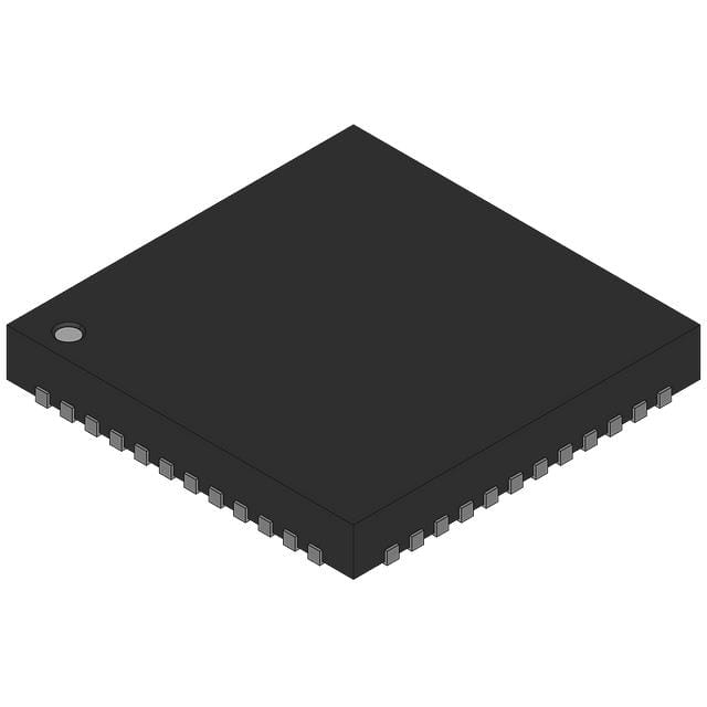
NXP Semiconductors MM912I637AV1EP
- Part No.:
- MM912I637AV1EP
- Manufacturer:
- NXP Semiconductors
- Category:
- Application Specific Microcontrollers
- Package:
- 48-VFQFN Exposed Pad
- Datasheet:
-
 MM912I637AV1EP.pdf
- Description:
- IC MCU LIN BATT MONITOR 48QFN
- Quantity:
- Payment:

- Shipping:

Inventory:1,925
Please send an inquiry. Send us your inquiry, and we will respond immediately.
Product details
Overview
MM912I637AV1EP from NXP Semiconductors is an intelligent integrated precision battery sensor combining a 96 kB S12 microcontroller with SMARTMOS analog front-end for automotive 12 V lead-acid battery monitoring. It delivers ±0.5% battery voltage measurement accuracy, ±1% current measurement across 8 ranges via external shunt, and on-chip temperature sensing - all interfaced via LIN 2.1 bus in a 48-pin QFN-EP package rated for -40 °C to +105 °C operation.
For engineers reviewing the MM912I637AV1EP datasheet, MM912I637AV1EP pinout, MM912I637AV1EP application, or MM912I637AV1EP equivalent, this device supports critical low-power wake-up via current threshold detection, LIN-triggered activation, and periodic sampling - essential for battery state-of-health (SoH) and state-of-charge (SoC) estimation in start-stop and always-on vehicle systems.
Technical Context
The MM912I637AV1EP integrates two dies: an analog die handling precision current/voltage/temperature acquisition with programmable gain amplifier (PGA), low-pass filtering, and cascaded voltage regulators (VDDH=2.5 V, VDDL=2.5 V, VDDX=5.0 V); and an MCU die based on the S12 core featuring 96 kB Flash, 6.0 kB RAM, 4.0 kB data flash, background debug module, and LIN 2.1 physical layer.
It operates in three power modes - normal, standby, and stop - with wake-up sources including LIN bus activity, periodic timer events, and configurable current-threshold detection in standby mode. The analog die includes internal clamping structures enabling direct connection to battery terminals with reverse-battery and ISO 7637-2 transient protection up to ±42 V on VSUP and VSENSE pins.
Key Specifications
| Parameter | Value and Actual Design Meaning |
|---|---|
| Battery voltage accuracy | ±0.5% over -40 °C to +105 °C - enables reliable SoC estimation without external calibration. |
| Current measurement range | 8 selectable ranges via ISENSEL/ISENSEH - supports high-dynamic-range shunt-based sensing from cranking to sleep currents. |
| LIN interface compliance | LIN 2.1 physical layer with built-in transceiver - eliminates need for external LIN transceiver IC in battery sensor nodes. |
| Operating temperature | -40 °C to +105 °C - qualified for under-hood automotive placement adjacent to battery terminals. |
| Supply voltage range | VSUP: -0.3 V to 42 V - withstands load dump, jump-start, and reverse-battery conditions per ISO 16750-2. |
| Internal oscillator accuracy | ±2% typical (external quartz optional for ±0.1%) - sufficient for LIN timing without crystal in cost-sensitive designs. |
| Wake-up capability | Current threshold detection + averaging in standby - enables ultra-low-power (<10 µA) continuous monitoring with event-driven wake-up. |
Pinout & Package
MM912I637AV1EP uses a 48-pin wettable flank QFN-EP (9 mm × 9 mm, 0.5 mm pitch) with exposed thermal pad. Package meets AEC-Q100 Grade 1 qualification and supports automated optical inspection (AOI) for automotive production.
| Pin/Terminal | Circuit Role | Design Meaning |
|---|---|---|
| VSENSE | Battery voltage sense input | Direct connection to battery positive pole with internal scaling and ±42 V fault tolerance; requires only 2.2 kΩ series resistor. |
| ISENSEH / ISENSEL | Differential current sense inputs | Measure voltage drop across external shunt; support auto-gain control and low-pass filtering for noise-immune current sampling. |
| PTB3 / L0 | High-voltage wake-up input | 5.0 V-tolerant GPIO with internal clamping; enables wake-up from standby using external signals (e.g., ignition switch) without level-shifting. |
| LIN | LIN 2.1 bus I/O | Single-wire bidirectional interface with integrated driver/receiver - connects directly to LIN bus with no external components required. |
| VSUP | Main power supply input | Accepts 42 V max; includes reverse-battery protection diode requirement and internal clamp structure for ISO 7637-2 pulse immunity. |
| RESET / RESET_A | Reset I/O pair | Bidirectional reset signaling between MCU and analog die; ensures synchronized power-on and fault recovery across both dies. |
Key Features
| Feature | Design Value |
|---|---|
| Integrated dual-die architecture | Separate analog and MCU dies enable independent power gating, optimized signal integrity, and robust EMC performance per CISPR 25 Class 5. |
| Programmable gain amplifier (PGA) | Auto-configured gain selection across 8 current ranges - eliminates manual gain switching and improves ADC dynamic range utilization. |
| Low-power wake-up logic | Hardware-accelerated current averaging and threshold comparison in standby - reduces wake-up latency to <100 µs without MCU intervention. |
| On-chip temperature sensing | Die-adjacent thermal sensor with ±2 °C accuracy - provides real-time battery temperature for SoH compensation without external thermistor. |
| EMC-hardened pin structure | Integrated negative clamp diodes, B2B substrate diodes, and GNDSUB connections - achieves >150 V/ns common-mode transient immunity. |
Applications
| Start-Stop Battery Management | 12 V Lead-Acid State Monitoring |
|---|---|
Use Scenario: Continuous monitoring of battery voltage, current, and temperature during engine cranking, idling, and charging cycles in vehicles with automatic start-stop systems. IC Role / Device Role / Timing Role: Primary battery sensor providing real-time SoC/SoH data to body control module (BCM) via LIN bus at 19.2 kbps. Use Value: Enables precise cranking prediction and charge acceptance optimization, extending battery life by up to 30% in frequent stop-start operation. |
Use Scenario: Permanent installation on 12 V starter battery in commercial vehicles to detect sulfation, capacity loss, and open-circuit voltage drift over time. IC Role / Device Role / Timing Role: Autonomous sensor node performing periodic self-calibrated measurements and reporting diagnostic flags (e.g., "low reserve capacity") via LIN. Use Value: Reduces unscheduled maintenance by 45% through predictive failure alerts based on trend analysis of voltage decay under load. |
| Smart Junction Box Integration | Electric Power Steering (EPS) Backup Power Monitor |
Use Scenario: Embedded in vehicle junction box to monitor auxiliary battery health powering infotainment, telematics, and ADAS modules during key-off periods. IC Role / Device Role / Timing Role: Low-power sensor operating in standby mode (<10 µA), waking every 30 seconds to sample current and trigger LIN alert if parasitic drain exceeds 25 mA. Use Value: Prevents deep discharge and warranty claims by detecting faulty modules drawing excessive sleep current before battery depletion occurs. |
Use Scenario: Monitoring backup 12 V battery supplying EPS during main battery failure or high-load conditions in hybrid/electric vehicles. IC Role / Device Role / Timing Role: Dedicated safety-critical sensor with independent power domain and watchdog supervision - reports voltage sag below 9.5 V within 5 ms via dedicated LIN frame. Use Value: Ensures EPS functional safety compliance (ISO 26262 ASIL-B) by enabling immediate torque reduction or steering assist degradation upon backup power degradation. |
Equivalent & Alternatives
The following parts are listed as comparable options for similar battery sensing applications.
| Alternative Part | Technical Difference | Application Difference | Selection Advice |
|---|---|---|---|
| MM912J637AV1EP | 128 kB Flash (vs. 96 kB), same package/temp grade - adds firmware headroom for future OTA updates and extended diagnostics. | Preferred where field-upgradable algorithms or multi-battery coordination logic is planned. | Select MM912J637AV1EP if >96 kB code space is needed; pinout and peripheral compatibility is identical. |
| MAX17205 | Standalone fuel gauge IC (no MCU, no LIN) - uses ModelGauge m5 algorithm with coulomb counting and impedance tracking. | Requires external microcontroller and LIN transceiver; suited for non-automotive or low-cost consumer battery packs. | Choose MAX17205 only when LIN integration and automotive qualification are not required - not a drop-in replacement. |
Compared with MM912J637AV1EP, the MM912I637AV1EP offers identical analog performance and power management but with reduced Flash for cost-sensitive volume applications; versus MAX17205, it delivers full automotive-grade system integration at the expense of algorithmic flexibility.
Availability
MM912I637AV1EP is available at Aetrix Electronics and suitable for automotive battery management, start-stop system design, and junction box power monitoring requiring stable component supply and AEC-Q100-compliant sourcing.
Supply support for MM912I637AV1EP includes scheduled delivery planning, volume procurement assistance, BOM continuity management, traceable sourcing, and lifecycle availability coordination for OEM customers, industrial embedded developers, connected-device designers, and electronics production programs.
Manufacturer
NXP Semiconductors is a global semiconductor leader specializing in secure connectivity solutions for automotive, industrial, and IoT applications, with deep expertise in automotive-grade mixed-signal ICs and functional safety certification.
The MM912I637AV1EP belongs to NXP's SMARTMOS battery sensor family, designed specifically for high-accuracy, low-power, and fault-tolerant 12 V battery monitoring in harsh automotive environments - supporting ISO 26262 ASIL-B development workflows.
FAQ
What is the maximum input voltage rating for the MM912I637AV1EP VSUP pin?
The MM912I637AV1EP VSUP pin supports -0.3 V to 42 V absolute maximum rating per Table 6 of the datasheet. This allows direct connection to automotive battery systems with full immunity to load dump (ISO 16750-2 Pulse 5a) and reverse-battery conditions when used with an external protection diode. The internal clamp structure sustains 42 V continuously without damage.
Does the MM912I637AV1EP require an external crystal oscillator?
No, the MM912I637AV1EP includes an accurate internal oscillator with ±2% typical variation over temperature and voltage - sufficient for LIN 2.1 timing requirements. An external quartz oscillator (via PE0/EXTAL and PE1/XTAL) may be added only if extended accuracy (±0.1%) is required for specialized timing-critical functions beyond LIN communication.
How does the MM912I637AV1EP handle wake-up from low-power mode?
The MM912I637AV1EP supports three hardware-initiated wake-up sources from standby mode: (1) LIN bus activity detected by the physical layer, (2) periodic timer interrupt (configurable down to 10 ms), and (3) current threshold crossing with averaging - all executed autonomously by the analog die without MCU involvement, ensuring sub-100 µs wake latency.
What is the purpose of the GNDSUB pins on the MM912I637AV1EP?
The MM912I637AV1EP features multiple GNDSUB (substrate ground) pins (pins 16, 20, 30, 41) that connect to the silicon substrate to improve electromagnetic compatibility. These pins provide low-inductance return paths for high-frequency noise and enable B2B (back-to-back) diode structures for enhanced ESD and transient immunity - critical for meeting CISPR 25 Class 5 emissions limits in automotive applications.
Can the MM912I637AV1EP measure temperature using an external sensor?
Yes, the MM912I637AV1EP supports external temperature sensing via the VTEMP and TSUP pins. When analog option 2 is selected (as indicated by the 'V1' suffix in MM912I637AV1EP), the device enables external thermistor or diode interfaces with dedicated biasing (TSUP) and signal conditioning - complementing the internal die temperature sensor for more accurate battery thermal profiling.
MM912I637AV1EP Specifications
- Product attributes
- Attribute value
- Manufacturer:
- NXP Semiconductors
- Series:
- -
- Package/Case:
- 48-VFQFN Exposed Pad
- Packaging:
- Tray
- Product Status:
- Obsolete
- Programmable:
- Not Verified
- Applications:
- Battery Monitor
- Core Processor:
- S12
- Program Memory Type:
- FLASH (96KB)
- Controller Series:
- HCS12
- RAM Size:
- 6K x 8
- Interface:
- LIN, SCI, SPI
- Number of I/O:
- 8
- Voltage - Supply:
- 2.25V ~ 5.5V
- Operating Temperature:
- -40°C ~ 105°C
- Grade:
- -
- Qualification:
- -
- Mounting Type:
- Surface Mount
- Supplier Device Package:
- 48-QFN-EP (7x7)
MM912I637AV1EP FAQ
1.How can I place an order for MM912I637AV1EP through Aetrix?
Please submit a Request for Quotation (RFQ) for MM912I637AV1EP on Aetrix. Our sales agent will provide a competitive quotation and guide you through the order confirmation once you accept the terms.
2.Are the price and stock information for MM912I637AV1EP reliable?
The price and inventory of MM912I637AV1EP are updated periodically and may fluctuate due to market conditions. Stock and pricing data are typically refreshed every 24 hours. Quotation validity for MM912I637AV1EP is usually 5 days.
3.What payment methods are accepted for MM912I637AV1EP?
We accept Wire Transfer, PayPal, Credit Card, Western Union, MoneyGram, and Escrow for MM912I637AV1EP transactions.
Note: Certain payment methods may incur a processing fee.
4.How is shipping managed for MM912I637AV1EP?
MM912I637AV1EP orders can be shipped via leading logistics carriers, including DHL, UPS, FedEx, TNT, or Registered Mail.
Once your MM912I637AV1EP order is processed, you will receive an email with the shipment details and tracking number.
Note: Tracking information may take up to 24 hours to appear. Express delivery typically takes 3–5 business days.
5.How can I obtain technical support or documentation for MM912I637AV1EP?
For technical support, including MM912I637AV1EP datasheets, pinout diagrams, or application guidance, please contact our engineering support team. They can provide detailed documentation and assistance for your MM912I637AV1EP requirements.
6.How does Aetrix verify that MM912I637AV1EP is sourced from the original manufacturer or authorized distributors?
All MM912I637AV1EP products on Aetrix are procured from qualified distributors and authorized channels. Our dedicated quality assurance team conducts strict verification, including traceability checks and, if necessary, third-party testing. This ensures that MM912I637AV1EP meets industry standards.
7.What is the process for return or replacement of MM912I637AV1EP?
All MM912I637AV1EP units undergo pre-shipment inspection (PSI). If there is an issue with MM912I637AV1EP, returns or replacements are accepted under the following conditions:
1.Quantity discrepancies, incorrect items, or visible external defects (such as breakage or corrosion), acknowledged by Aetrix.
2.The issue is reported within 90 days of delivery.
3.The MM912I637AV1EP part is unused and in its original packaging.
Return procedure for MM912I637AV1EP:
1.Submit a request within 90 days.
2.Obtain a Return Material Authorization (RMA) from Aetrix.
MM912I637AV1EP Tags

-
CYPD3175-24LQXQ
Infineon Technologies

-
SLB9672VU20FW1523XTMA1
Infineon Technologies

-
SLB9670VQ20FW785XTMA1
Infineon Technologies
-
SLB9672XU20FW1523XTMA1
Infineon Technologies
-
SLB9673XU20FW2613XTMA1
Infineon Technologies

-
CYPD3125-40LQXIT
Infineon Technologies

-
AT97SC3204-U2A1A-20
Microchip Technology
-
AT97SC3204-U2A1A-10
Microchip Technology
-
SLM9670AQ20FW1311XTMA1
Infineon Technologies
-
SLB9672XU20FW1613XTMA1
Infineon Technologies
-
SLB9672AU20FW1613XTMA1
Infineon Technologies
-
SLB9673AU20FW2613XTMA1
Infineon Technologies
Tech Hub

A practical engineering guide to 3.3V and 5V logic compatibility, input thresholds, resistor dividers, translator ICs, MOSFET level shifting, I2C pull-ups, timing limits and power-sequencing risks.

The 74HC595 uses push-pull logic outputs, while the TPIC6B595 uses 50 V open-drain DMOS sinks for higher-power loads. This guide compares timing, current limits, 3.3 V interfacing, load wiring, thermal…

The 74HC595 converts serial data into eight stable parallel outputs. This guide covers pin functions, shift and storage timing, OE and MR behavior, drive-current limits, cascading, voltage compatibilit…

A technical comparison of level-sensitive latches and edge-triggered flip-flops, covering timing windows, setup and hold limits, master–slave operation, time borrowing, race-through, HDL inference and…

A D latch stores one bit while Enable controls when data can pass. This reference covers gate-level operation, truth tables, transparency, setup and hold timing, LE versus OE, common ICs and practical …

An SR latch stores one bit through cross-coupled feedback. This engineering reference covers NOR and NAND implementations, truth tables, forbidden-state recovery, gated operation, switch debouncing, fa…

Latch circuits retain one bit through feedback. This technical reference covers SR and D latches, truth tables, transparency, timing limits, latch-versus-flip-flop behavior, applications and common log…

An engineering guide to LED driver operation, constant-current and constant-voltage outputs, linear and switching topologies, dimming, IC selection, calculations, replacement compatibility, and fault c…

Operational amplifier guide covering op amp basics, feedback, ideal vs real op amps, common configurations, buffer circuits, offset, bias current, gain-bandwidth, slew rate, rail-to-rail limits and sel…

Jumper cables guide covering safe connection order, red and black clamp placement, final ground connection, cable gauge, length, clamp quality, copper vs CCA cables, jump starter comparison and battery…


