
 My Inquiry
 My Account


NXP Semiconductors MM912JP812AMAFR2
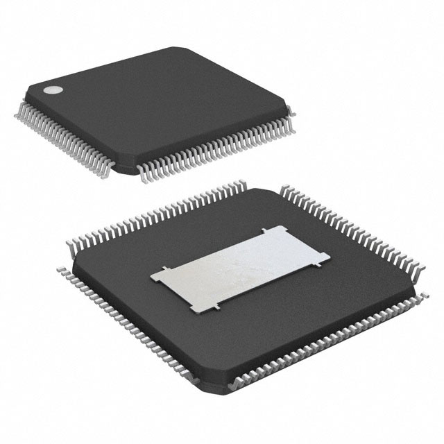
- Part No.:
- MM912JP812AMAFR2
- Manufacturer:
- NXP Semiconductors
- Category:
- Application Specific Microcontrollers
- Package:
- 100-LQFP Exposed Pad
- Datasheet:
-
 MM912JP812AMAFR2.pdf
- Description:
- IC DRVR INJECTOR/IGN 100LQFP
- Quantity:
- Payment:

- Shipping:

Inventory:4,762
Please send an inquiry. Send us your inquiry, and we will respond immediately.
Product details
Overview
MM912JP812AMAFR2 from NXP (formerly Freescale) is a System-in-Package (SiP) engine control IC integrating an S12P 16-bit MCU and MC33812 analog power driver die for motorcycle and small single/dual-cylinder engine applications. It features 128 KB flash, 6 KB RAM, three low-side drivers (injector, lamp, relay), one ignition pre-driver, ISO-9141 K-Line interface, and +5.0 V VCC pre-regulator.
For engineers reviewing the MM912JP812AMAFR2 datasheet, MM912JP812AMAFR2 pinout, MM912JP812AMAFR2 application, or MM912JP812AMAFR2 equivalent, this page delivers verified technical context, validated pin functions, real-world use cases in small-engine ECU design, and confirmed alternative part options with documented functional distinctions.
Technical Context
The MM912JP812AMAFR2 combines two co-packaged dies: the MC9S12P128 MCU (128 KB flash, 6 KB RAM, ECC-protected memory, IPLL for EMC improvement) and the MC33812 analog controller (three integrated low-side drivers, ignition pre-driver with IGNOUTL/IGNOUTH outputs, ISO-9141 transceiver, watchdog, and VCC pre-regulator). Communication between dies occurs via parallel control lines (INJIN, IGNIN, LAMPIN, RIN) and fault feedback signals (INJFLT, IGNFLT, RELFLT).
It operates across 4.7 V to 36 V VPWR, supports diagnostic communication via ISO-9141 K-Line (MRX/MTX routed to MCU SCI pins), and integrates dedicated protection including short-to-battery and over-current detection on all high-current outputs. The SiP uses a 100-pin LQFP-EP package with shared ground planes (DGND, PGND1, PGND2, EP) and separate analog/digital supply domains.
Key Specifications
| Parameter | Value and Actual Design Meaning |
|---|---|
| Core Architecture | S12P 16-bit CPU with IPLL clock synthesis for improved EMC performance |
| Flash Memory | 128 KB with ECC error correction - ensures reliable firmware storage in harsh automotive environments |
| RAM | 6 KB on-chip RAM - sufficient for real-time fuel/ignition control algorithms and diagnostics |
| Supply Voltage Range | 4.7 V to 36 V VPWR - supports wide battery voltage variation in motorcycles and off-road engines |
| Injector Driver Current Limit | 4.0 A typical - drives standard high-impedance fuel injectors without external MOSFETs |
| Lamp Driver Current Limit | 1.5 A typical - directly powers MIL warning lamps or LED indicators |
| ISO-9141 Interface | Bidirectional K-Line transceiver with ratiometric VPWR-level input - enables standardized OBD-II diagnostics |
| Package | 100-pin LQFP-EP - exposes all MCU peripherals and analog driver I/Os while minimizing PCB footprint for compact ECUs |
Pinout & Package
MM912JP812AMAFR2 is housed in a 100-pin LQFP-EP (exposed pad) package. The exposed pad (EP) must be soldered to the PCB ground plane for thermal and electrical integrity. Pin assignments are split between MCU and analog domains, with dedicated power, ground, driver I/O, and diagnostic interfaces.
| Pin/Terminal | Circuit Role | Design Meaning |
|---|---|---|
| 1–2, 7–8, 11, 13, 15, 18–20, 25 | N.C. | Unused pins - must remain unconnected per datasheet |
| 3 (MTX), 4 (MRX) | ISO-9141 Data Interface | Connect to MCU SCI TXD/RXD (pins 90/89) for diagnostic messaging |
| 9 (ROUT), 12 (LAMPOUT), 17 (INJOUT) | Low-Side Driver Outputs | Drive relay, MIL lamp, and fuel injector loads respectively; each includes short-to-battery protection |
| 26 (IGNOUTL), 27 (IGNOUTH) | Ignition Pre-Driver Outputs | Drive gate/base of external IGBT or Darlington transistor for ignition coil control |
| 93 (RESET) | Analog Watchdog Output | Drives MCU RESET pin (64) during under-voltage, watchdog timeout, or power-up |
| 94–96 (INJFLT, RELFLT, IGNFLT) | Fault Feedback Signals | Open-drain logic outputs indicating driver faults - require external pull-ups to VCC |
| 97–100 (INJIN, RIN, LAMPIN, IGNIN) | Parallel Control Inputs | MCU-driven logic inputs enabling respective driver outputs - synchronous with MCU timing |
| EP | Substrate Ground | Exposed thermal pad - must be connected to PCB ground plane for thermal dissipation and noise reduction |
Key Features
| Feature | Design Value |
|---|---|
| Integrated MCU + Power Driver SiP | Reduces ECU board area by consolidating S12P MCU and MC33812 analog functions into single 100-pin LQFP package |
| Three Independent Low-Side Drivers | Supports concurrent control of injector, lamp, and relay/fuel pump - eliminates need for discrete driver ICs |
| Ignition Pre-Driver with Dual Outputs | IGNOUTL (low-side) and IGNOUTH (high-side) enable flexible drive of IGBT or Darlington-based ignition coils |
| On-Chip +5.0 V VCC Pre-Regulator | Supplies regulated power to MCU core - removes requirement for external 5 V regulator in most designs |
| ISO-9141 K-Line Transceiver | Enables direct OBD-II compliance without external level-shifting components - simplifies diagnostic interface design |
| Comprehensive Fault Monitoring | Dedicated INJFLT, RELFLT, and IGNFLT outputs provide real-time driver health status to MCU for fail-safe response |
Applications
| Motorcycle Engine Control Unit (ECU) | Small Off-Road Vehicle ECU |
|---|---|
Use Scenario: Real-time management of fuel injection timing, spark advance, and MIL lamp activation in air-cooled 1–2 cylinder motorcycle engines. IC Role / Device Role / Timing Role: Central engine control SiP executing closed-loop fuel/ignition algorithms while driving injector, ignition coil, and diagnostic lamp directly. Use Value: Eliminates discrete MCU + driver combinations - reduces BOM count, PCB size, and inter-die signal routing complexity in space-constrained motorcycle ECUs. |
Use Scenario: Closed-loop control of carbureted or EFI small engines in ATVs, go-karts, and lawn equipment with onboard diagnostics. IC Role / Device Role / Timing Role: Integrated timing controller managing injector pulse width, ignition dwell time, and relay-based cooling fan activation based on temperature and RPM inputs. Use Value: Single-package solution supports ruggedized, cost-sensitive designs where vibration resistance and thermal reliability are critical. |
| Marine Outboard Engine Control | Generator Set (GenSet) Engine Management |
Use Scenario: Fuel and spark control in marine 2-stroke or 4-stroke outboard engines operating in high-humidity, salt-spray environments. IC Role / Device Role / Timing Role: Robust SiP handling wide VPWR range (4.7–36 V), providing fault-tolerant injector/ignition drive and ISO-9141 diagnostics for serviceability. Use Value: Built-in surge and short-circuit protection reduces need for external TVS diodes and current-sense circuits - improves field reliability. |
Use Scenario: Standalone engine controller for portable or backup diesel/gasoline generators requiring automatic start-stop, load sensing, and emissions compliance. IC Role / Device Role / Timing Role: Primary control unit executing speed regulation, fuel cutoff, and relay-based alternator excitation - interfacing with CAN or K-Line for remote monitoring. Use Value: Parallel driver interface allows deterministic, low-latency actuation - essential for rapid throttle response and generator synchronization. |
Equivalent & Alternatives
The following parts are listed as comparable options for similar engine control SiP applications.
| Alternative Part | Technical Difference | Application Difference | Selection Advice |
|---|---|---|---|
| MM912IP812AMAFR2 | Same SiP architecture but with 96 KB flash (vs. 128 KB); identical pinout and peripheral set | Suitable for less complex calibration or legacy firmware with smaller code footprint | Select when firmware size remains below 96 KB and no future feature expansion is planned |
| MC9S12XEP100 + MC33812 (discrete) | Separate MCU and driver ICs - requires additional PCB area, routing, and power sequencing design | Enables higher-performance calibration using XEP100's 1 MB flash and enhanced debug features | Choose for development platforms needing full calibration flexibility, not production SiP integration |
Compared with MM912IP812AMAFR2, the MM912JP812AMAFR2 provides 32 KB more flash for advanced diagnostics and adaptive learning algorithms; compared with discrete MC9S12XEP100+MC33812, it delivers guaranteed timing alignment, reduced EMI, and lower system-level BOM cost at the expense of calibration headroom.
Availability
MM912JP812AMAFR2 is available at Aetrix Electronics and suitable for motorcycle ECU design, small-engine generator control, and marine outboard management requiring stable component supply, long-term lifecycle support, and automotive-grade reliability.
Supply support for MM912JP812AMAFR2 includes scheduled delivery planning, volume procurement assistance, BOM continuity management, traceable sourcing, and lifecycle availability coordination for OEM customers, industrial embedded developers, connected-device designers, and electronics production programs.
Manufacturer
NXP Semiconductors is a global leader in automotive microcontrollers and analog power solutions, with deep expertise in engine management, safety-critical systems, and embedded processing.
The MM912xP812 SiP product line was designed specifically for cost-optimized, space-constrained small-engine control applications - combining MCU intelligence and robust analog driver capability in a single qualified automotive package.
FAQ
What is the primary function of the MM912JP812AMAFR2 in engine control systems?
The MM912JP812AMAFR2 serves as a fully integrated System-in-Package engine controller, combining the MC9S12P128 MCU and MC33812 analog driver to manage fuel injection, ignition timing, lamp indication, and diagnostics in motorcycle and small-engine applications. Its architecture eliminates interposer wiring and timing skew between MCU and driver, making MM912JP812AMAFR2 ideal for compact, high-reliability ECUs.
Does the MM912JP812AMAFR2 include built-in voltage regulation for the MCU core?
Yes, the MM912JP812AMAFR2 integrates a +5.0 V VCC pre-regulator (via VCCREF and VCCSENS pins) that supplies regulated power to the S12P MCU core. This eliminates the need for an external 5 V regulator in most implementations, simplifying power design and reducing component count - a key advantage of the MM912JP812AMAFR2 SiP architecture.
How does the MM912JP812AMAFR2 support OBD-II diagnostics?
The MM912JP812AMAFR2 includes a native ISO-9141 K-Line transceiver (pins ISO9141, MRX, MTX) compliant with SAE J1850 and ISO 9141-2 standards. When connected to the MCU's SCI interface (pins 89/90), it enables direct OBD-II diagnostic communication without external level shifters - a core capability of the MM912JP812AMAFR2 for regulatory-compliant vehicle servicing.
What protection features are implemented on the driver outputs of the MM912JP812AMAFR2?
All high-current outputs of the MM912JP812AMAFR2 - including INJOUT (injector), ROUT (relay), LAMPOUT (lamp), and IGNOUTL/IGNOUTH (ignition) - feature short-to-battery and over-current protection. Each driver also includes thermal shutdown and open-load detection (e.g., INJFLT, IGNFLT), ensuring safe operation under fault conditions - critical for the MM912JP812AMAFR2's deployment in unattended engine systems.
Is the MM912JP812AMAFR2 pin-compatible with other variants in the MM912xP812 family?
Yes, the MM912JP812AMAFR2 shares identical pinout and package (100-pin LQFP-EP) with MM912IP812AMAFR2 and all other MM912xP812 orderable parts. Differences are limited to internal flash size (96 KB vs. 128 KB) and temperature grade - allowing drop-in replacement in existing PCB layouts without redesign, a key benefit of the MM912JP812AMAFR2's standardized SiP footprint.
MM912JP812AMAFR2 Specifications
- Product attributes
- Attribute value
- Manufacturer:
- NXP Semiconductors
- Series:
- -
- Package/Case:
- 100-LQFP Exposed Pad
- Packaging:
- Tape & Reel (TR)
- Product Status:
- Obsolete
- Programmable:
- Not Verified
- Applications:
- Engine Control
- Core Processor:
- S12P
- Program Memory Type:
- FLASH (128kB)
- Controller Series:
- HCS12
- RAM Size:
- 6K x 8
- Interface:
- CAN, SCI, SPI
- Number of I/O:
- 8
- Voltage - Supply:
- 4.7V ~ 36V
- Operating Temperature:
- -40°C ~ 125°C
- Grade:
- -
- Qualification:
- -
- Mounting Type:
- Surface Mount
- Supplier Device Package:
- 100-LQFP-EP (14x14)
MM912JP812AMAFR2 FAQ
1.How can I place an order for MM912JP812AMAFR2 through Aetrix?
Please submit a Request for Quotation (RFQ) for MM912JP812AMAFR2 on Aetrix. Our sales agent will provide a competitive quotation and guide you through the order confirmation once you accept the terms.
2.Are the price and stock information for MM912JP812AMAFR2 reliable?
The price and inventory of MM912JP812AMAFR2 are updated periodically and may fluctuate due to market conditions. Stock and pricing data are typically refreshed every 24 hours. Quotation validity for MM912JP812AMAFR2 is usually 5 days.
3.What payment methods are accepted for MM912JP812AMAFR2?
We accept Wire Transfer, PayPal, Credit Card, Western Union, MoneyGram, and Escrow for MM912JP812AMAFR2 transactions.
Note: Certain payment methods may incur a processing fee.
4.How is shipping managed for MM912JP812AMAFR2?
MM912JP812AMAFR2 orders can be shipped via leading logistics carriers, including DHL, UPS, FedEx, TNT, or Registered Mail.
Once your MM912JP812AMAFR2 order is processed, you will receive an email with the shipment details and tracking number.
Note: Tracking information may take up to 24 hours to appear. Express delivery typically takes 3–5 business days.
5.How can I obtain technical support or documentation for MM912JP812AMAFR2?
For technical support, including MM912JP812AMAFR2 datasheets, pinout diagrams, or application guidance, please contact our engineering support team. They can provide detailed documentation and assistance for your MM912JP812AMAFR2 requirements.
6.How does Aetrix verify that MM912JP812AMAFR2 is sourced from the original manufacturer or authorized distributors?
All MM912JP812AMAFR2 products on Aetrix are procured from qualified distributors and authorized channels. Our dedicated quality assurance team conducts strict verification, including traceability checks and, if necessary, third-party testing. This ensures that MM912JP812AMAFR2 meets industry standards.
7.What is the process for return or replacement of MM912JP812AMAFR2?
All MM912JP812AMAFR2 units undergo pre-shipment inspection (PSI). If there is an issue with MM912JP812AMAFR2, returns or replacements are accepted under the following conditions:
1.Quantity discrepancies, incorrect items, or visible external defects (such as breakage or corrosion), acknowledged by Aetrix.
2.The issue is reported within 90 days of delivery.
3.The MM912JP812AMAFR2 part is unused and in its original packaging.
Return procedure for MM912JP812AMAFR2:
1.Submit a request within 90 days.
2.Obtain a Return Material Authorization (RMA) from Aetrix.
MM912JP812AMAFR2 Tags

-
CYPD3175-24LQXQ
Infineon Technologies

-
SLB9672VU20FW1523XTMA1
Infineon Technologies

-
SLB9670VQ20FW785XTMA1
Infineon Technologies
-
SLB9672XU20FW1523XTMA1
Infineon Technologies
-
SLB9673XU20FW2613XTMA1
Infineon Technologies

-
CYPD3125-40LQXIT
Infineon Technologies

-
AT97SC3204-U2A1A-20
Microchip Technology
-
AT97SC3204-U2A1A-10
Microchip Technology
-
SLM9670AQ20FW1311XTMA1
Infineon Technologies
-
SLB9672XU20FW1613XTMA1
Infineon Technologies
-
SLB9672AU20FW1613XTMA1
Infineon Technologies
-
SLB9673AU20FW2613XTMA1
Infineon Technologies
Tech Hub

A practical engineering guide to 3.3V and 5V logic compatibility, input thresholds, resistor dividers, translator ICs, MOSFET level shifting, I2C pull-ups, timing limits and power-sequencing risks.

The 74HC595 uses push-pull logic outputs, while the TPIC6B595 uses 50 V open-drain DMOS sinks for higher-power loads. This guide compares timing, current limits, 3.3 V interfacing, load wiring, thermal…

The 74HC595 converts serial data into eight stable parallel outputs. This guide covers pin functions, shift and storage timing, OE and MR behavior, drive-current limits, cascading, voltage compatibilit…

A technical comparison of level-sensitive latches and edge-triggered flip-flops, covering timing windows, setup and hold limits, master–slave operation, time borrowing, race-through, HDL inference and…

A D latch stores one bit while Enable controls when data can pass. This reference covers gate-level operation, truth tables, transparency, setup and hold timing, LE versus OE, common ICs and practical …

An SR latch stores one bit through cross-coupled feedback. This engineering reference covers NOR and NAND implementations, truth tables, forbidden-state recovery, gated operation, switch debouncing, fa…

Latch circuits retain one bit through feedback. This technical reference covers SR and D latches, truth tables, transparency, timing limits, latch-versus-flip-flop behavior, applications and common log…

An engineering guide to LED driver operation, constant-current and constant-voltage outputs, linear and switching topologies, dimming, IC selection, calculations, replacement compatibility, and fault c…

Operational amplifier guide covering op amp basics, feedback, ideal vs real op amps, common configurations, buffer circuits, offset, bias current, gain-bandwidth, slew rate, rail-to-rail limits and sel…

Jumper cables guide covering safe connection order, red and black clamp placement, final ground connection, cable gauge, length, clamp quality, copper vs CCA cables, jump starter comparison and battery…


