
 My Inquiry
 My Account


Monolithic Power Systems Inc. MP5505AGL-P
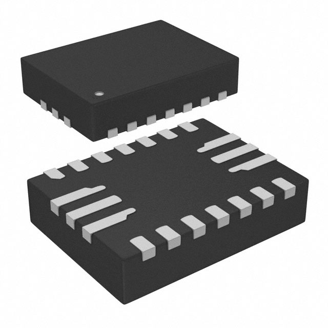
- Part No.:
- MP5505AGL-P
- Manufacturer:
- Monolithic Power Systems Inc.
- Category:
- Power Management - Specialized
- Package:
- 20-PowerTFQFN
- Datasheet:
-
 MP5505AGL-P.pdf
- Description:
- IC REG BOOST 7V 4A
- Quantity:
- Payment:

- Shipping:

Inventory:2,899
Please send an inquiry. Send us your inquiry, and we will respond immediately.
Product details
Overview
MP5505AGL-P from Monolithic Power Systems is a 7V-input, 4A integrated energy storage and management unit with lossless bi-directional buck/boost architecture for SSD/HDD power hold-up. It features programmable input current limit (up to 4.6A), 6V bus clamping, adjustable storage/release voltages (e.g., 12V/4.2V), and thermal protection in a QFN-20 (3mm × 4mm) package.
For engineers reviewing the MP5505AGL-P datasheet, MP5505AGL-P pinout, MP5505AGL-P application, or MP5505AGL-P equivalent, key selection criteria include input-current-limit resistor programming (ILIM), storage-voltage feedback divider (FBS), release-voltage feedback (FBB), dv/dt slew-rate control (DVDT), and power-good indicator timing (PGIN/PGS).
Technical Context
The MP5505AGL-P integrates two independent power paths: an input-current-limiting hot-swap FET (50mΩ) with dv/dt-controlled soft-start, and a bi-directional energy management core using shared inductor SW and internal 70mΩ/60mΩ switches. Its patented architecture enables lossless charge (boost mode) and regulated discharge (buck-release mode at 500kHz fixed-frequency COT control).
It implements dual feedback loops - FBB senses VB for bus regulation and release triggering (UVLO threshold 2.2V), while FBS senses STRG for storage voltage regulation (reference 0.79V). ENCH enables/disables only the charge/release circuitry, decoupling it from the input limiter controlled by EN.
Key Specifications
| Parameter | Value and Actual Design Meaning |
|---|---|
| Input Voltage Range | 2.7V to 7V - supports wide-range industrial and storage supply rails including 3.3V, 5V, and 12V-derived intermediate buses. |
| Max Input Current Limit | 4.6A - set via ILIM resistor (e.g., 1.07kΩ); prevents inrush and sustains steady-state load during hot-swap events. |
| Storage Voltage Range | VIN to 30V - programmable via FBS feedback (0.79V reference); enables efficient high-voltage energy storage (e.g., 12V) to minimize capacitor size. |
| Release Voltage Range | 2.7V to 6V - set via FBB feedback (0.79V reference); defines minimum bus voltage before buck-release activates (e.g., 4.2V for 5V systems). |
| Buck-Release Frequency | 500kHz - fixed-frequency constant-on-time (COT) control ensures fast transient response and seamless transition from boost to buck mode. |
| Thermal Shutdown | 150°C with 30°C hysteresis - protects die during sustained overload or poor PCB thermal design; recovers autonomously after cooldown. |
| Bus Clamping Voltage | 6V - limits VB overvoltage during transients or fault conditions without external TVS, enhancing system robustness. |
| Power-Good Indicators | PGIN (open-drain, 20μs delay) and PGS (open-drain, 20μs delay) - provide precise status signaling for system sequencing and firmware monitoring. |
Pinout & Package
MP5505AGL-P is housed in a thermally enhanced QFN-20 (3mm × 4mm) package with exposed thermal pad (PGND-connected). Pin 13 is NC; all other pins are functionally assigned per the manufacturer's top-view layout.
| Pin/Terminal | Circuit Role | Design Meaning |
|---|---|---|
| DVDT | Slew-rate control | Capacitor-to-GND sets VB start-up time (default ~0.9ms); prevents input inrush during hot-plug. |
| TPOR | Power-on-reset delay | Capacitor-to-GND programs delay before VB charging begins (default 0.4ms); ensures stable EN/ENCH sequencing. |
| ILIM | Current-limit programming | Resistor-to-GND sets input FET current limit (4.6A @ 1.07kΩ); critical for inrush and steady-state protection. |
| PGIN | Bus power-good output | Open-drain signal high when VB ≥ 1.03×VFBB (0.813V); low indicates release initiation or UVLO. |
| PGS | Storage power-good output | Open-drain signal high when STRG ≥ 0.95×VFBS (0.75V); monitors storage capacitor readiness. |
| EN | Global enable | Active-high control for entire IC - disables both input limiter and charge/release circuits when low. |
| ENCH | Charge/release enable | Independent active-high control - must be high for STRG charging and buck-release operation. |
| SW | Switch node | Connects to external inductor (e.g., 4.7μH); carries bidirectional current during boost (charge) and buck (release) phases. |
| STRG | Storage voltage rail | High-voltage node (up to 30V) connected to bulk storage capacitor; supplies energy during input outage. |
| BST | Bootstrap supply | Drives high-side switch gate; requires 100nF ceramic cap to SW for proper gate drive during release. |
| FBB | Bus feedback input | Senses VB via resistor divider to set release threshold and regulate bus voltage during normal operation. |
| FBS | Storage feedback input | Senses STRG via resistor divider to set target storage voltage (e.g., 12V) and maintain regulation. |
| ICH | Boost current limit | Resistor-to-GND sets peak boost current (500mA default); adjusts pre-charge and boost-mode current capability. |
| VIN | Main input supply | Accepts 2.7–7V unregulated input; requires local 0.1μF ceramic decoupling and optional TVS for spike suppression. |
| VB | Internal bus voltage | Regulated output rail (2.7–6V); powers downstream DC/DCs; requires 22–47μF ceramic capacitor near pin. |
| PGND | Power ground | High-current return path for VIN, VB, SW, STRG; must be low-impedance and tied to thermal pad. |
| AGND | Analog ground | Signal reference for feedback, EN, ENCH, and PG pins; should be separated from PGND and joined at single point. |
| VBO | Boost output | Internal node between input FET and bus; connects to SW through external inductor in boost configuration. |
| CST | High-side driver storage | Supports high-side switch operation when STRG ≈ VB; enables efficient charge transfer near voltage crossover. |
Key Features
| Feature | Design Value |
|---|---|
| Lossless bi-directional energy management | Patented buck/boost topology eliminates storage capacitor discharge losses; achieves >90% release efficiency at 1A load. |
| Programmable input current limiting | Integrated 50mΩ hot-swap FET with resistor-set limit (4.1–4.6A); replaces discrete current-limit IC + MOSFET solutions. |
| Independent charge/release control | Separate EN and ENCH pins allow staged activation - e.g., enable input limiter first, then charge circuitry after bus stabilization. |
| Adjustable storage and release voltages | FBS and FBB feedback pins support custom voltage setpoints (e.g., 12V storage / 4.2V release) via standard resistor dividers. |
| Robust power-good signaling | Dual open-drain indicators (PGIN/PGS) with 20μs delay and hysteresis prevent false triggering during transients. |
| Thermal and overvoltage protection | 150°C shutdown with 30°C hysteresis + 6V bus clamp ensure safe operation under fault, overload, or layout-induced heating. |
Applications
| Solid-State Drive (SSD) Power Hold-Up | Hard-Disk Drive (HDD) Crash Protection |
|---|---|
Use Scenario: Sudden AC/DC adapter disconnect during write operations. IC Role / Device Role / Timing Role: MP5505AGL-P stores energy during normal operation and releases it to maintain 5V bus for 20+ ms, enabling graceful NAND flash write completion and metadata save. Use Value: Prevents data corruption and file-system damage by sustaining regulated VB long enough for controller firmware to execute emergency flush routines. | Use Scenario: Instantaneous power loss during HDD head retraction. IC Role / Device Role / Timing Role: Acts as backup power source that triggers buck-release mode when VB drops below 4.2V, powering spindle motor and voice-coil actuator for safe park sequence. Use Value: Eliminates mechanical wear and head crash risk by guaranteeing ≥15ms of 5V hold-up at 1.2A, meeting ATA-7 "dying gasp" requirements. |
| Industrial PLC I/O Module Backup | Network Attached Storage (NAS) Controller Keep-Alive |
Use Scenario: Brownout on 24VDC field power feeding isolated 5V logic rails. IC Role / Device Role / Timing Role: Charges 12V storage capacitor from 5V bus during nominal operation; discharges to sustain 5V rail during 100ms input dip, preserving real-time I/O state and communication buffers. Use Value: Enables deterministic fail-safe behavior - no watchdog reset or comms dropout - even with 50ms–200ms input interruptions common in factory environments. | Use Scenario: UPS switchover delay or brief grid interruption affecting NAS motherboard power. IC Role / Device Role / Timing Role: Provides 5V/3.3V rail hold-up to keep ARM-based SoC and SATA controller operational while UPS stabilizes, preventing RAID array deactivation or journal corruption. Use Value: Maintains system responsiveness and data integrity by delivering ≥100ms of regulated power at 800mA, allowing uninterrupted disk spin-down and cache flush. |
Equivalent & Alternatives
The following parts are listed as comparable options for similar energy storage and management applications.
| Alternative Part | Technical Difference | Application Difference | Selection Advice |
|---|---|---|---|
| MP5504AGL-Z | Lower 3A max input current limit; identical pinout and feature set except reduced ILIM range and no CST pin. | Targeted at lower-power SSDs or embedded modules where <3A hold-up current suffices; lacks CST-driven high-efficiency near-VB operation. | Select when cost sensitivity outweighs need for 4A+ current handling or optimal efficiency at low ΔV (STRG–VB). |
| TPS65023BRSBR | Triple-output PMIC with integrated Li-ion charger; no bi-directional energy storage; 2.5A max buck output; different topology and control scheme. | Designed for portable battery-backed systems, not AC/DC-powered storage hold-up; lacks programmable release voltage and storage management logic. | Only consider for battery-coupled designs requiring charging + regulation - not a functional substitute for MP5505AGL-P's lossless capacitor-based hold-up. |
Compared with MP5504AGL-Z, MP5505AGL-P delivers higher current capability and extended efficiency at low voltage differentials via CST; versus TPS65023BRSBR, it provides dedicated, high-efficiency capacitor-based hold-up without battery dependency or complex charging algorithms.
Availability
MP5505AGL-P is available at Aetrix Electronics and suitable for solid-state drive power hold-up, hard-disk drive crash protection, and industrial PLC I/O module backup requiring stable component supply, full production traceability, and long-term lifecycle support.
Supply support for MP5505AGL-P includes scheduled delivery planning, volume procurement assistance, BOM continuity management, traceable sourcing, and lifecycle availability coordination for OEM customers, industrial embedded developers, connected-device designers, and electronics production programs.
Manufacturer
Monolithic Power Systems (MPS) is a fabless semiconductor company specializing in high-performance analog and power ICs, with over 20 years of leadership in DC/DC conversion, motor drivers, and energy management solutions.
The MP5505A product line was designed specifically for ultra-compact, high-efficiency power hold-up in storage subsystems - addressing the growing need for lossless, programmable, and thermally robust energy buffering in SSDs, HDDs, and industrial edge controllers.
FAQ
What is the minimum recommended storage capacitance for 20ms hold-up at 1A with 12V storage and 4.2V release?
The required storage capacitance is calculated as Cs = (V²STORAGE − V²RELEASE) × τDASP / (2 × IRELEASE × VRELEASE) × 1.1 for efficiency margin. Substituting values yields Cs ≈ 1500μF. A 2200μF/16V POSCAP or low-ESR electrolytic capacitor is recommended to ensure margin and reliability across temperature.
Can MP5505AGL-P operate with VIN = 3.3V and still charge a 12V storage capacitor?
Yes. The integrated boost converter raises STRG above VIN - up to 30V - regardless of input voltage. With VIN = 3.3V, the device enters boost mode once STRG exceeds VB and uses the internal 70mΩ HS-FET and 60mΩ LS-FET to pump energy, achieving full 12V storage with appropriate inductor (e.g., 4.7μH) and feedback divider.
How does reverse-current protection work during energy release?
Reverse-current protection is enforced by the input hot-swap FET, which turns off when VIN falls below VB (or below the PGIN threshold of ~0.79V). This blocks backflow from STRG → VB → VIN, ensuring stored energy flows only to the bus rail and downstream loads - critical for system isolation during brownouts.
Is the TPOR pin required to be used, or can it be left floating?
TPOR can be left floating to use the default 0.4ms power-on-reset delay. However, for systems requiring precise sequencing - such as enabling ENCH only after VB has fully settled - a capacitor (e.g., 100nF for 1ms delay) must be connected to TPOR and GND to avoid accidental release-mode entry during startup.
What is the purpose of the CST pin, and what happens if it is left unconnected?
CST stores charge to drive the high-side switch gate when STRG voltage approaches VB, enabling efficient charge transfer near voltage crossover. If left unconnected, the device still operates but with reduced efficiency in the 10–20% ΔV range (e.g., 12V→11V), increasing conduction loss and thermal stress on internal switches.
Does MP5505AGL-P support automatic transition between charge and release modes without external intervention?
Yes. The device continuously monitors FBB and FBS voltages. When VB drops below the release threshold (set by FBB), it automatically disables boost mode and initiates buck-release - no external control signal or microcontroller action is needed. This autonomous behavior ensures deterministic hold-up response within microseconds.
What is the maximum allowable storage voltage, and what failure mode occurs if exceeded?
The absolute maximum storage voltage (VSTRG) is 35V. Exceeding this risks permanent damage to the internal 70mΩ/60mΩ switches and BST driver circuitry. Operation above 30V is outside recommended conditions and voids parametric guarantees - sustained overvoltage may trigger immediate thermal shutdown or latent die degradation.
MP5505AGL-P Specifications
- Product attributes
- Attribute value
- Manufacturer:
- Monolithic Power Systems Inc.
- Series:
- -
- Package/Case:
- 20-PowerTFQFN
- Packaging:
- Tape & Reel (TR)
- Product Status:
- Active
- Applications:
- Battery Backup
- Current - Supply:
- 2mA (Max)
- Voltage - Supply:
- 2.7V ~ 7V
- Operating Temperature:
- -40°C ~ 125°C
- Grade:
- -
- Qualification:
- -
- Mounting Type:
- Surface Mount
- Supplier Device Package:
- 20-QFN (3x4)
MP5505AGL-P FAQ
1.How can I place an order for MP5505AGL-P through Aetrix?
Please submit a Request for Quotation (RFQ) for MP5505AGL-P on Aetrix. Our sales agent will provide a competitive quotation and guide you through the order confirmation once you accept the terms.
2.Are the price and stock information for MP5505AGL-P reliable?
The price and inventory of MP5505AGL-P are updated periodically and may fluctuate due to market conditions. Stock and pricing data are typically refreshed every 24 hours. Quotation validity for MP5505AGL-P is usually 5 days.
3.What payment methods are accepted for MP5505AGL-P?
We accept Wire Transfer, PayPal, Credit Card, Western Union, MoneyGram, and Escrow for MP5505AGL-P transactions.
Note: Certain payment methods may incur a processing fee.
4.How is shipping managed for MP5505AGL-P?
MP5505AGL-P orders can be shipped via leading logistics carriers, including DHL, UPS, FedEx, TNT, or Registered Mail.
Once your MP5505AGL-P order is processed, you will receive an email with the shipment details and tracking number.
Note: Tracking information may take up to 24 hours to appear. Express delivery typically takes 3–5 business days.
5.How can I obtain technical support or documentation for MP5505AGL-P?
For technical support, including MP5505AGL-P datasheets, pinout diagrams, or application guidance, please contact our engineering support team. They can provide detailed documentation and assistance for your MP5505AGL-P requirements.
6.How does Aetrix verify that MP5505AGL-P is sourced from the original manufacturer or authorized distributors?
All MP5505AGL-P products on Aetrix are procured from qualified distributors and authorized channels. Our dedicated quality assurance team conducts strict verification, including traceability checks and, if necessary, third-party testing. This ensures that MP5505AGL-P meets industry standards.
7.What is the process for return or replacement of MP5505AGL-P?
All MP5505AGL-P units undergo pre-shipment inspection (PSI). If there is an issue with MP5505AGL-P, returns or replacements are accepted under the following conditions:
1.Quantity discrepancies, incorrect items, or visible external defects (such as breakage or corrosion), acknowledged by Aetrix.
2.The issue is reported within 90 days of delivery.
3.The MP5505AGL-P part is unused and in its original packaging.
Return procedure for MP5505AGL-P:
1.Submit a request within 90 days.
2.Obtain a Return Material Authorization (RMA) from Aetrix.
MP5505AGL-P Tags

-
TPS2511DGNR
Texas Instruments

-
UTC2000/MG
Microchip Technology

-
TUSB320HAIRWBR
Texas Instruments

-
TPS61252DSGR
Texas Instruments

-
PI5USB30216CXUAEX
Diodes Incorporated

-
SN6501DBVR
Texas Instruments

-
CYPD3177-24LQXQT
Infineon Technologies
-
SN6501QDBVRQ1
Texas Instruments

-
STUSB1600AQTR
STMicroelectronics

-
SN6505BDBVR
Texas Instruments
-
SN6501DBVT
Texas Instruments

-
TPS65150PWPR
Texas Instruments
Tech Hub

Operational amplifier guide covering op amp basics, feedback, ideal vs real op amps, common configurations, buffer circuits, offset, bias current, gain-bandwidth, slew rate, rail-to-rail limits and sel…

Jumper cables guide covering safe connection order, red and black clamp placement, final ground connection, cable gauge, length, clamp quality, copper vs CCA cables, jump starter comparison and battery…

LDO regulator guide covering low dropout voltage, power dissipation, thermal design, PSRR, output noise, capacitor stability, adjustable LDO circuits, LDO vs buck converter and datasheet selection chec…

Conditional Access Module guide covering CAM meaning, CI/CI+ interface, smart card authorization, DVB security workflow, TV and set-top box compatibility, internal electronics, ESD protection, connecto…

Guide to electronic component obsolescence covering EOL risk, PCN/PDN notices, last-time buy planning, replacement options, form-fit-function validation, counterfeit risk and BOM lifecycle management.

18650 battery guide covering lithium-ion cell basics, 3.6V/3.7V voltage, 4.2V charging, mAh and Wh capacity, protected cells, chargers, BMS, series-parallel packs, holders, welding and sourcing checks.…

Hall effect sensor guide covering working principle, linear and digital sensors, Arduino circuits, current sensing, speed detection, automotive applications, A3144 examples, signal filtering and datash…

Product Change Notification guide for electronic components, covering PCN meaning, PCN vs PDN/EOL, common change types, risk levels, form-fit-function review, engineering validation, BOM control, LTB/L…

A practical guide to blend door actuators, covering HVAC function, symptoms, location, AC and heater issues, reset and calibration, replacement cost, electrical diagnosis, compatibility checks, and rep…

Engineering guide to Raspberry Pi alternatives, covering chip-level differences, Orange Pi, ROCK, Jetson, Banana Pi, NanoPi, Compute Module, Pico, GPIO, camera, HAT compatibility, and replacement risks…


