
 My Inquiry
 My Account


NXP Semiconductors MPL115A1
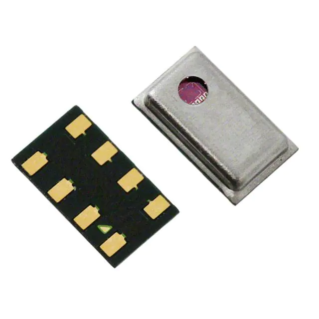
- Part No.:
- MPL115A1
- Manufacturer:
- NXP Semiconductors
- Category:
- Pressure Sensors, Transducers
- Package:
- 8-TLGA
- Datasheet:
-
 MPL115A1.pdf
- Description:
- SENSOR 16.68PSIA 10BIT 8LGA
- Quantity:
- Payment:

- Shipping:

Inventory:2,190
Please send an inquiry. Send us your inquiry, and we will respond immediately.
Product details
Overview
MPL115A1 from NXP Semiconductors is an absolute pressure sensor IC with integrated MEMS transducer and signal-conditioning circuitry, delivering digitized pressure and temperature outputs via SPI interface. It operates across 50 kPa to 115 kPa range with ±1 kPa accuracy over –40 °C to +105 °C, consumes only 5 μA in active mode, and resides in a 3 × 5 × 1.2 mm LGA-8 package-enabling barometric sensing in space-constrained portable electronics.
For engineers reviewing the MPL115A1 datasheet, MPL115A1 pinout, MPL115A1 application, or MPL115A1 equivalent, this page delivers verified technical context, calibrated performance parameters, SPI timing constraints, host-side compensation requirements, and validated alternative options for barometric measurement systems requiring low-power, factory-trimmed digital pressure sensing.
Technical Context
The MPL115A1 integrates a MEMS pressure die with on-chip ADC, temperature sensor, and calibration coefficient ROM. All sensor data-including raw 10-bit pressure (Padc) and temperature (Tadc) values plus four 14–16-bit factory coefficients (a0, b1, b2, c12)-are accessed via memory-mapped SPI reads; no internal compensation is performed.
Host microcontroller execution of the documented second-order polynomial (Pcomp = a0 + (b1 + c12×Tadc)×Padc + b2×Tadc) is mandatory to derive compensated absolute pressure. The device supports SPI clock frequencies up to 8 MHz, requires external 1 μF decoupling on CAP pin, and enters sub-1 μA shutdown when SHDN is pulled low.
Key Specifications
| Parameter | Value and Actual Design Meaning |
|---|---|
| Pressure Range | 50 kPa to 115 kPa absolute - covers sea-level to ~1500 m altitude with vacuum reference. |
| Accuracy | ±1 kPa from –20 °C to +85 °C - defines maximum uncompensated error before host algorithm application. |
| Supply Voltage | 2.375 V to 5.5 V - enables direct interfacing with 3.3 V or 5 V microcontrollers without level-shifting. |
| Active Current | 5 μA average at 1 sample/second - enables multi-year battery life in portable weather or altimeter devices. |
| SPI Clock Max | 8 MHz - supports fast readout of all 10-bit ADC registers and 16-byte coefficient set within <100 μs. |
| Conversion Time | 1.6 ms to 3 ms - defines minimum interval between CONVERT command and valid register data. |
| Wake-up Time | 3 ms to 5 ms after SHDN deassertion - sets latency budget for responsive wake-from-sleep pressure sampling. |
Pinout & Package
Package: LGA-8 (TSON8, SOT1769-1), 3.0 mm × 5.0 mm × 1.2 mm, RoHS-compliant surface-mount package with exposed cavity for pressure port access.
| Pin/Terminal | Circuit Role | Design Meaning |
|---|---|---|
| VDD | Power supply input | Accepts 2.375–5.5 V; powers internal regulator and analog front-end. |
| CAP | Regulator output decoupling | Requires 1 μF ceramic capacitor to GND for stable internal voltage reference. |
| GND | Ground reference | Common return for analog and digital circuits; must be low-impedance. |
| SHDN | Shutdown control | Pull low to reduce current to ≤1 μA; high-impedance SPI pins during sleep. |
| CS | Chip select | Active-low enable for SPI communication; must meet tSCS ≥125 ns setup. |
| DOUT | SPI serial data output | 3-state output; drives MSB-first data aligned to SCLK falling edge. |
| DIN | SPI serial data input | Accepts command bytes (e.g., 24h for CONVERT); sampled on SCLK rising edge. |
| SCLK | SPI clock input | Supports up to 8 MHz; requires tCLKH/tCLKL ≥62.5 ns for reliable timing. |
Key Features
| Feature | Design Value |
|---|---|
| Factory-calibrated coefficients | Unique a0, b1, b2, c12 stored in on-chip ROM - eliminates per-unit calibration effort and enables one-time host-side coefficient storage. |
| Monotonic ADC outputs | 10-bit Padc and Tadc outputs guarantee monotonic response - prevents erroneous pressure jumps during interpolation or filtering. |
| Integrated regulator with CAP pin | On-die LDO stabilized by external 1 μF capacitor - reduces PCB BOM count and improves PSRR vs. direct VDD-sensing designs. |
| Low-power shutdown mode | ≤1 μA quiescent current with full pin isolation - allows seamless integration into duty-cycled IoT sensor nodes without leakage concerns. |
| Memory-mapped SPI interface | 6-bit address space (00h–12h) with R/W bit - simplifies driver development using standard SPI peripheral libraries without custom protocol stacks. |
Applications
| Barometric Weather Station | Portable Altimeter |
|---|---|
Use Scenario: Standalone handheld or desktop unit measuring local atmospheric pressure for weather forecasting and trend analysis. IC Role / Device Role / Timing Role: Primary absolute pressure transducer providing digitized, temperature-compensated kPa output via SPI to MCU. Use Value: ±1 kPa accuracy over –20 °C to +85 °C enables reliable detection of 8–10 hPa pressure changes corresponding to ~100 m altitude shifts. | Use Scenario: Battery-powered hiking or aviation altimeter tracking elevation change based on ambient air pressure. IC Role / Device Role / Timing Role: Core barometric sensor feeding real-time pressure data to host MCU for altitude calculation using international standard atmosphere model. Use Value: 5 μA active current and 1 μA shutdown current extend single-CR2032 battery life beyond 2 years at 1 Hz sampling. |
| Hard Disk Drive (HDD) Head Positioning | Industrial Environmental Monitor |
Use Scenario: Closed-loop pressure compensation inside HDD enclosures to maintain optimal head-to-disk flying height under varying ambient conditions. IC Role / Device Role / Timing Role: Precision absolute pressure reference enabling dynamic actuator tuning to counteract altitude- or temperature-induced air density variations. Use Value: Factory-trimmed coefficients and 0.15 kPa resolution support sub-micron head positioning stability across operating temperature range. | Use Scenario: Fixed-mount enclosure monitoring for HVAC, cleanroom, or industrial process control where pressure differentials indicate filter clogging or system integrity loss. IC Role / Device Role / Timing Role: Digital barometric sensor interfaced to industrial MCU or PLC for long-term environmental logging and alarm triggering. Use Value: –40 °C to +105 °C operating range ensures reliability in unconditioned industrial cabinets or outdoor enclosures without external thermal management. |
Equivalent & Alternatives
The following parts are listed as comparable options for similar absolute pressure sensing applications.
| Alternative Part | Technical Difference | Application Difference | Selection Advice |
|---|---|---|---|
| BMP280 | Includes on-chip temperature compensation and I²C/SPI dual interface; higher typical accuracy (±0.12 hPa) but wider supply range (1.71–3.6 V). | Targets higher-precision consumer wearables and drones; lacks extended industrial temp range (–40 °C to +85 °C only). | Select BMP280 when on-device compensation and lower power at 3.3 V are prioritized over extended temperature operation. |
| MS5637 | Offers 0.012 hPa RMS noise and 24-bit ADC; requires external MCU for coefficient storage but provides higher resolution (0.01 kPa). | Used in professional-grade altimeters and dive computers; requires more complex host firmware due to variable-order compensation. | Choose MS5637 when ultra-low noise and sub-10 cm altitude resolution are required, accepting increased firmware overhead. |
Compared with BMP280 and MS5637, the MPL115A1 delivers verified ±1 kPa accuracy across –40 °C to +105 °C in a smaller 3×5 mm footprint with simpler 10-bit data handling-making it optimal for cost-sensitive, space-constrained industrial and portable barometers where host-based compensation is already implemented.
Availability
MPL115A1 is available at Aetrix Electronics and suitable for barometric weather stations, portable altimeters, HDD environmental compensation, and industrial environmental monitors requiring stable component supply, long-lifecycle assurance, and RoHS-compliant LGA packaging.
Supply support for MPL115A1 includes scheduled delivery planning, volume procurement assistance, BOM continuity management, traceable sourcing, and lifecycle availability coordination for OEM customers, industrial embedded developers, connected-device designers, and electronics production programs.
Manufacturer
NXP Semiconductors is a global semiconductor company headquartered in Eindhoven, Netherlands, specializing in secure connectivity solutions for automotive, industrial, and IoT applications.
The MPL115A1 belongs to NXP's precision analog sensor family, designed specifically for low-cost, low-power digital barometric measurement in portable and industrial equipment where factory-calibrated MEMS pressure sensing with host-side compensation is preferred.
FAQ
What is the primary function of the MPL115A1?
The MPL115A1 is an absolute pressure sensor IC that measures ambient atmospheric pressure from 50 kPa to 115 kPa and outputs digitized pressure and temperature readings via SPI. It does not perform internal compensation; instead, it provides factory-stored calibration coefficients so the host microcontroller can compute compensated absolute pressure using a documented polynomial equation. This architecture enables high accuracy while minimizing on-die complexity and power consumption in the MPL115A1.
Does the MPL115A1 include built-in temperature compensation?
No, the MPL115A1 does not perform on-chip temperature or nonlinearity compensation. It outputs raw 10-bit pressure (Padc) and temperature (Tadc) ADC values along with four factory-programmed coefficients (a0, b1, b2, c12) stored in internal ROM. The host microcontroller must execute the specified second-order compensation algorithm-using these values-to derive the final compensated pressure result. This design keeps the MPL115A1's active current at just 5 μA and avoids fixed-function logic that would limit flexibility or increase die size.
What are the critical timing requirements for SPI communication with the MPL115A1?
The MPL115A1 supports SPI clock frequencies up to 8 MHz, with minimum SCLK high/low times of 62.5 ns each. Chip select (CS) must be asserted ≥125 ns before the first SCLK edge (tSCS), and data must be held ≥30 ns after SCLK low (tHOLD). Data becomes valid ≤32 ns after the SCLK falling edge (tDDLY). These constraints ensure reliable register reads-including coefficient data at addresses 04h–0Bh-and command writes like the 24h CONVERT instruction. Violating tSCS or tHOLD risks corrupted coefficient or conversion data in the MPL115A1.
How is the MPL115A1 powered and decoupled?
The MPL115A1 accepts a supply voltage from 2.375 V to 5.5 V on the VDD pin and draws only 5 μA in active mode. A 1 μF ceramic capacitor must be placed between the CAP pin and GND to stabilize the internal regulator output-this is not optional and directly impacts measurement stability. The GND pin serves as the common reference for both analog and digital sections. No additional LDO or filtering is required, making the MPL115A1 compatible with standard 3.3 V or 5 V microcontroller rails without external regulators.
Can the MPL115A1 be used in harsh industrial environments?
Yes, the MPL115A1 is rated for continuous operation from –40 °C to +105 °C and features robust handling guidelines for reflow, cleaning, and mechanical mounting. Its LGA-8 package (SOT1769-1) uses a metal lid with an exposed pressure port, and NXP explicitly recommends protecting the vent hole during PCB cleaning or ultrasonic processes. The device withstands 1000 kPa overpressure and supports no-clean solder pastes to avoid chemical exposure to the MEMS element-making the MPL115A1 suitable for sealed industrial enclosures, automotive cabin modules, and ruggedized portable instrumentation.
MPL115A1 Specifications
- Product attributes
- Attribute value
- Manufacturer:
- NXP Semiconductors
- Series:
- -
- Package/Case:
- 8-TLGA
- Packaging:
- Tray
- Product Status:
- Obsolete
- Applications:
- Board Mount
- Pressure Type:
- Absolute
- Operating Pressure:
- 7.25PSI ~ 16.68PSI (50kPa ~ 115kPa)
- Output Type:
- SPI
- Output:
- 10 b
- Accuracy:
- ±0.145PSI (±1kPa)
- Voltage - Supply:
- 2.375V ~ 5.5V
- Port Size:
- -
- Port Style:
- No Port
- Features:
- Shutdown Mode, Standby Mode
- Termination Style:
- SMD (SMT) Tab
- Maximum Pressure:
- 145.04PSI (1000kPa)
- Operating Temperature:
- -40°C ~ 105°C
- Grade:
- -
- Qualification:
- -
- Mounting Type:
- Surface Mount
- Supplier Device Package:
- 8-LGA (5x3)
MPL115A1 FAQ
1.How can I place an order for MPL115A1 through Aetrix?
Please submit a Request for Quotation (RFQ) for MPL115A1 on Aetrix. Our sales agent will provide a competitive quotation and guide you through the order confirmation once you accept the terms.
2.Are the price and stock information for MPL115A1 reliable?
The price and inventory of MPL115A1 are updated periodically and may fluctuate due to market conditions. Stock and pricing data are typically refreshed every 24 hours. Quotation validity for MPL115A1 is usually 5 days.
3.What payment methods are accepted for MPL115A1?
We accept Wire Transfer, PayPal, Credit Card, Western Union, MoneyGram, and Escrow for MPL115A1 transactions.
Note: Certain payment methods may incur a processing fee.
4.How is shipping managed for MPL115A1?
MPL115A1 orders can be shipped via leading logistics carriers, including DHL, UPS, FedEx, TNT, or Registered Mail.
Once your MPL115A1 order is processed, you will receive an email with the shipment details and tracking number.
Note: Tracking information may take up to 24 hours to appear. Express delivery typically takes 3–5 business days.
5.How can I obtain technical support or documentation for MPL115A1?
For technical support, including MPL115A1 datasheets, pinout diagrams, or application guidance, please contact our engineering support team. They can provide detailed documentation and assistance for your MPL115A1 requirements.
6.How does Aetrix verify that MPL115A1 is sourced from the original manufacturer or authorized distributors?
All MPL115A1 products on Aetrix are procured from qualified distributors and authorized channels. Our dedicated quality assurance team conducts strict verification, including traceability checks and, if necessary, third-party testing. This ensures that MPL115A1 meets industry standards.
7.What is the process for return or replacement of MPL115A1?
All MPL115A1 units undergo pre-shipment inspection (PSI). If there is an issue with MPL115A1, returns or replacements are accepted under the following conditions:
1.Quantity discrepancies, incorrect items, or visible external defects (such as breakage or corrosion), acknowledged by Aetrix.
2.The issue is reported within 90 days of delivery.
3.The MPL115A1 part is unused and in its original packaging.
Return procedure for MPL115A1:
1.Submit a request within 90 days.
2.Obtain a Return Material Authorization (RMA) from Aetrix.
MPL115A1 Tags
-
DPS368XTSA1
Infineon Technologies
-
DPS310XTSA1
Infineon Technologies
-
LPS22HHTR
STMicroelectronics

-
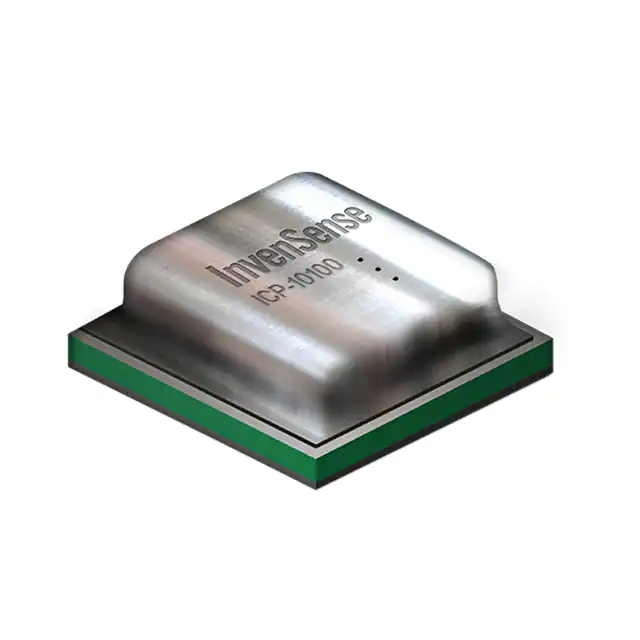
ICP-20100
TDK InvenSense
-
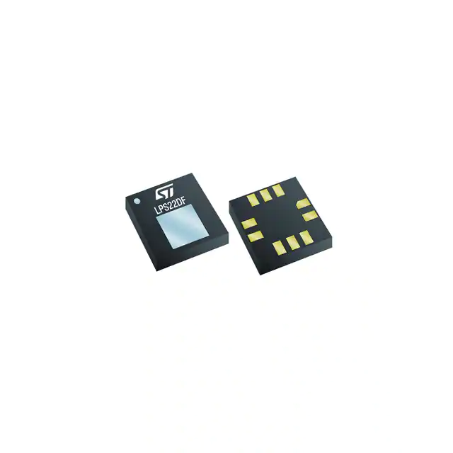
ICP-10110
TDK InvenSense
-
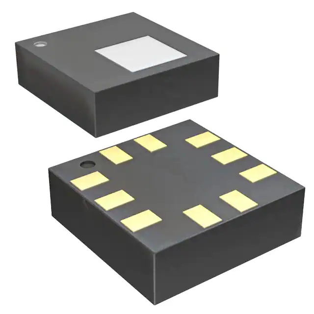
LPS22DFTR
STMicroelectronics
-
LPS22HBTR
STMicroelectronics
-
BMP390
Bosch Sensortec
-
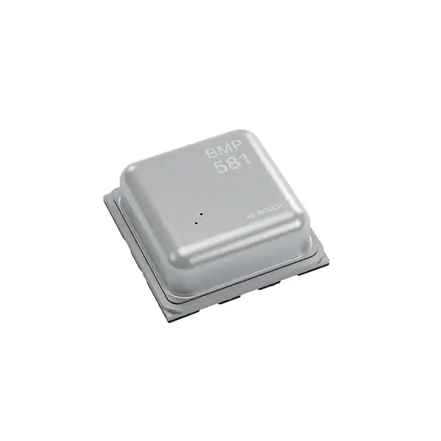
BMP581
Bosch Sensortec
-
BMP384
Bosch Sensortec
-
2511020213301
Würth Elektronik
-
ILPS22QSTR
STMicroelectronics
Tech Hub

A practical engineering guide to 3.3V and 5V logic compatibility, input thresholds, resistor dividers, translator ICs, MOSFET level shifting, I2C pull-ups, timing limits and power-sequencing risks.

The 74HC595 uses push-pull logic outputs, while the TPIC6B595 uses 50 V open-drain DMOS sinks for higher-power loads. This guide compares timing, current limits, 3.3 V interfacing, load wiring, thermal…

The 74HC595 converts serial data into eight stable parallel outputs. This guide covers pin functions, shift and storage timing, OE and MR behavior, drive-current limits, cascading, voltage compatibilit…

A technical comparison of level-sensitive latches and edge-triggered flip-flops, covering timing windows, setup and hold limits, master–slave operation, time borrowing, race-through, HDL inference and…

A D latch stores one bit while Enable controls when data can pass. This reference covers gate-level operation, truth tables, transparency, setup and hold timing, LE versus OE, common ICs and practical …

An SR latch stores one bit through cross-coupled feedback. This engineering reference covers NOR and NAND implementations, truth tables, forbidden-state recovery, gated operation, switch debouncing, fa…

Latch circuits retain one bit through feedback. This technical reference covers SR and D latches, truth tables, transparency, timing limits, latch-versus-flip-flop behavior, applications and common log…

An engineering guide to LED driver operation, constant-current and constant-voltage outputs, linear and switching topologies, dimming, IC selection, calculations, replacement compatibility, and fault c…

Operational amplifier guide covering op amp basics, feedback, ideal vs real op amps, common configurations, buffer circuits, offset, bias current, gain-bandwidth, slew rate, rail-to-rail limits and sel…

Jumper cables guide covering safe connection order, red and black clamp placement, final ground connection, cable gauge, length, clamp quality, copper vs CCA cables, jump starter comparison and battery…


