
 My Inquiry
 My Account


NXP Semiconductors MPL115A2T2
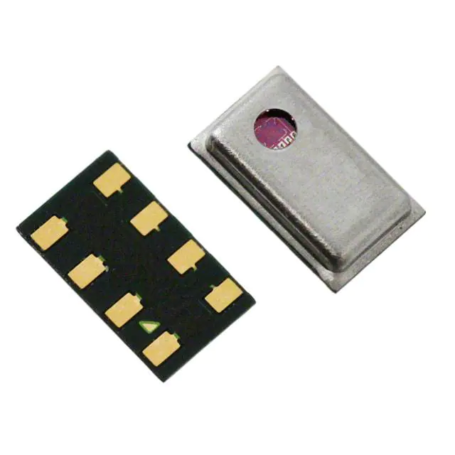
- Part No.:
- MPL115A2T2
- Manufacturer:
- NXP Semiconductors
- Category:
- Pressure Sensors, Transducers
- Package:
- 8-TLGA
- Datasheet:
-
 MPL115A2T2.pdf
- Description:
- SENSOR 16.68PSIA 10BIT 8LGA
- Quantity:
- Payment:

- Shipping:

Inventory:3,907
Please send an inquiry. Send us your inquiry, and we will respond immediately.
Product details
Overview
MPL115A2T2 from NXP Semiconductors is a miniature I²C digital barometric pressure sensor in an LGA-8 package, delivering absolute pressure measurements from 50 kPa to 115 kPa with ±1 kPa accuracy across –40 °C to +105 °C. It integrates a MEMS pressure transducer and signal-conditioning IC with factory-stored calibration coefficients, requiring host-side compensation to compute compensated barometric pressure. Its 5 × 3 × 1.2 mm footprint and 5 μA active current make it suitable for space- and power-constrained portable electronics.
For engineers reviewing the MPL115A2T2 datasheet, MPL115A2T2 pinout, MPL115A2T2 application, or MPL115A2T2 equivalent, this page provides verified technical context, validated pin functions, confirmed I²C interface behavior (7-bit address 0x60, 400 kHz max), real-world compensation algorithm dependencies, and documented alternative options for barometric sensing in portable, industrial, and environmental monitoring systems.
Technical Context
The MPL115A2T2 implements a two-stage signal chain: a MEMS-based absolute pressure sensor coupled with an integrated 10-bit ADC for simultaneous pressure and temperature digitization. Calibration data-including a0, b1, b2, and c12 coefficients stored in on-chip ROM-is read via I²C and used by the host microcontroller to execute a fixed-point polynomial compensation algorithm yielding compensated pressure output.
Its I²C interface operates at up to 400 kHz with standard 7-bit addressing (0x60), supports START CONVERSION command (0x12), and exposes register-mapped access to raw ADC outputs (0x00–0x03) and calibration coefficients (0x04–0x0B). Power management includes SHDN pin control enabling <1 μA shutdown current and wake-up time of 3–5 ms.
Key Specifications
| Parameter | Value and Actual Design Meaning |
|---|---|
| Pressure Range | 50 kPa to 115 kPa absolute - covers sea-level to ~1500 m altitude with vacuum reference. |
| Accuracy | ±1 kPa over –20 °C to +85 °C - enables reliable barometric altimetry and weather trend detection. |
| Supply Voltage | 2.375 V to 5.5 V - compatible with 3.3 V and 5 V logic domains without level shifting. |
| I²C Interface | 7-bit address 0x60, 400 kHz max clock - supports standard/fast-mode I²C with external 4.7 kΩ pull-ups. |
| Active Current | 5 μA average at 1 sample/second - extends battery life in wearable and IoT sensors. |
| Package | LGA-8 (SOT1769-1), 3.0 × 5.0 × 1.2 mm - surface-mount, RoHS-compliant, requires vented PCB cavity. |
| Operating Temp | –40 °C to +105 °C - qualified for automotive cabin, industrial enclosures, and outdoor equipment. |
Pinout & Package
LGA-8 package (SOT1769-1), 3.0 mm × 5.0 mm × 1.2 mm height, with exposed cavity for pressure port access. Requires vented PCB cutout aligned to die cavity.
| Pin/Terminal | Circuit Role | Design Meaning |
|---|---|---|
| VDD | Power supply input | Accepts 2.375–5.5 V; decoupling capacitor (1 µF) required between VDD and GND. |
| CAP | Capacitor connection | Connect 1 µF capacitor to GND to stabilize internal voltage reference. |
| GND | Ground reference | Common return path for analog and digital circuits; must be low-impedance. |
| SHDN | Shutdown control | Pull low to enter <1 μA shutdown mode; pull high for normal operation. |
| RST | Reset control | Pull low to disable I²C communication; releases automatically on rising edge. |
| NC | No connection | Not internally bonded; must remain unconnected on PCB. |
| SDA | I²C data line | Open-drain bidirectional line; requires 4.7 kΩ pull-up to VDD. |
| SCL | I²C clock line | Input-only clock line; requires 4.7 kΩ pull-up to VDD. |
Key Features
| Feature | Design Value |
|---|---|
| Factory-calibrated coefficients | Unique a0, b1, b2, c12 stored in ROM per unit - eliminates system-level calibration effort and ensures traceable accuracy. |
| Host-executed compensation | Fixed-point polynomial algorithm (Pcomp = a0 + (b1 + c12×Tadc)×Padc + b2×Tadc) - offloads computation to MCU while retaining precision. |
| Low-power shutdown | SHDN pin reduces current to ≤1 μA - enables duty-cycled operation in battery-powered altimeters and weather stations. |
| Vented LGA package | Exposed MEMS cavity accessible through PCB cutout - enables true absolute pressure measurement referenced to ambient air. |
| I²C register map | Memory-mapped registers for ADC outputs (0x00–0x03), coefficients (0x04–0x0B), and CONVERT command (0x12) - simplifies driver development and debug. |
Applications
| Barometric Altimetry | Portable Weather Monitoring |
|---|---|
Use Scenario: Measuring elevation change in handheld GPS devices or hiking wearables using atmospheric pressure gradients. IC Role / Device Role / Timing Role: Absolute pressure sensor providing 10-bit raw Padc and Tadc values to host MCU for compensated altitude calculation. Use Value: ±1 kPa accuracy translates to ~8.5 m vertical resolution at sea level, sufficient for trail navigation and activity tracking. | Use Scenario: Deploying compact, battery-operated weather stations for home or agricultural use. IC Role / Device Role / Timing Role: Primary barometric sensor feeding real-time pressure trends to ESP32 or similar MCU for local display and cloud upload. Use Value: 5 μA active current enables multi-month operation on coin-cell batteries when sampling once per minute. |
| Industrial Environmental Sensing | HDD Air Pressure Compensation |
Use Scenario: Monitoring cabinet pressure in telecom base stations or server racks to detect airflow blockage or seal failure. IC Role / Device Role / Timing Role: Absolute pressure transducer interfaced via I²C to industrial controller for periodic diagnostics. Use Value: –40 °C to +105 °C rating ensures stable operation inside sealed enclosures under thermal stress. | Use Scenario: Compensating head positioning in 2.5" and 3.5" hard disk drives based on ambient air density changes. IC Role / Device Role / Timing Role: Embedded pressure sensor supplying real-time Padc/Tadc to drive actuator compensation algorithms. Use Value: Factory-trimmed coefficients eliminate per-unit calibration overhead during HDD manufacturing. |
Equivalent & Alternatives
The following parts are listed as comparable options for similar absolute pressure sensing applications.
| Alternative Part | Technical Difference | Application Difference | Selection Advice |
|---|---|---|---|
| BMP280 | Integrated compensation engine; no host-side math required. Higher typical accuracy (±0.12 hPa). I²C/SPI dual interface. | Reduces MCU firmware load but increases BOM cost. Better suited for designs lacking computational headroom. | Select BMP280 if on-device compensation and SPI flexibility are prioritized over minimal footprint and ultra-low active current. |
| MS5637 | Higher resolution (24-bit ΔΣ ADC), wider range (10–1200 kPa), SPI-only interface. Requires external oscillator. | Supports altimetry above 10,000 m and underwater depth sensing. Not drop-in due to different pinout and protocol. | Choose MS5637 for extended-range or high-precision applications where I²C is not mandatory and board space allows larger package. |
Compared with BMP280 and MS5637, the MPL115A2T2 offers the smallest LGA footprint (3×5 mm), lowest active current (5 μA), and simplest I²C-only integration-making it optimal for size- and power-constrained portable barometers where host MCU resources are available for compensation math.
Availability
MPL115A2T2 is available at Aetrix Electronics and suitable for barometric altimetry, portable weather monitoring, and industrial environmental sensing requiring stable component supply and long-term lifecycle support.
Supply support for MPL115A2T2 includes scheduled delivery planning, volume procurement assistance, BOM continuity management, traceable sourcing, and lifecycle availability coordination for OEM customers, industrial embedded developers, connected-device designers, and electronics production programs.
Manufacturer
NXP Semiconductors is a global semiconductor company headquartered in Eindhoven, Netherlands, specializing in secure connectivity solutions for automotive, industrial, and IoT markets.
The MPL115A2 product line delivers miniature, low-power absolute pressure sensors targeting portable electronics and embedded environmental monitoring-designed to simplify integration of accurate barometric sensing without external calibration.
FAQ
What is the I²C address of the MPL115A2T2 and how is it configured?
The MPL115A2T2 uses a fixed 7-bit I²C address of 0x60 (1100000b), with write address 0xC0 and read address 0xC1. This address is hard-coded and cannot be changed via pins or registers. External 4.7 kΩ pull-up resistors are required on both SDA and SCL lines, and the device does not acknowledge the general call address (0x00). The MPL115A2T2 responds only to its assigned address and supports standard/fast-mode I²C up to 400 kHz.
Does the MPL115A2T2 perform on-chip pressure compensation, or is host processing required?
The MPL115A2T2 does not perform on-chip compensation. It outputs raw 10-bit pressure (Padc) and temperature (Tadc) ADC values along with factory-stored calibration coefficients (a0, b1, b2, c12) stored in ROM. Host microcontroller firmware must implement the documented fixed-point polynomial equation to compute compensated absolute pressure. This architecture minimizes sensor die complexity and power consumption while ensuring unit-specific accuracy.
What is the purpose of the CAP pin on the MPL115A2T2, and how should it be connected?
On the MPL115A2T2, the CAP pin connects to a 1 µF capacitor tied to GND. This capacitor stabilizes the internal voltage reference used by the ADC and signal conditioning circuitry, directly improving measurement repeatability and reducing noise-induced errors. The capacitor must be placed as close as possible to the CAP and GND pins, using a low-ESR ceramic type. Omitting or undersizing this capacitor results in increased pressure reading variance and degraded long-term stability.
How does the SHDN pin affect power consumption and communication readiness of the MPL115A2T2?
Driving the SHDN pin low places the MPL115A2T2 into shutdown mode, reducing supply current to ≤1 μA and placing all I²C pins (SDA, SCL, RST) in high-impedance state. To resume operation, SHDN must be pulled high, followed by a wake-up delay of 3–5 ms before issuing any I²C commands. During shutdown, all internal registers reset-requiring re-initialization and coefficient reload upon wake-up. This feature enables aggressive power cycling in battery-powered applications.
Is the MPL115A2T2 pin-compatible with other variants like MPL115A2T1, and what distinguishes them?
Yes, the MPL115A2T2 is pin-compatible with MPL115A2T1-the same LGA-8 (SOT1769-1) package, identical pinout, and identical electrical specifications. The suffix "T2" denotes tape-and-reel packaging (1000 pcs/reel), whereas "T1" also indicates tape-and-reel but may reflect earlier revision or minor handling differences. Both share identical functionality, timing, and register map. No PCB layout changes are needed when substituting between T1 and T2 variants.
MPL115A2T2 Specifications
- Product attributes
- Attribute value
- Manufacturer:
- NXP Semiconductors
- Series:
- -
- Package/Case:
- 8-TLGA
- Packaging:
- Tape & Reel (TR)
- Product Status:
- Obsolete
- Applications:
- Board Mount
- Pressure Type:
- Absolute
- Operating Pressure:
- 7.25PSI ~ 16.68PSI (50kPa ~ 115kPa)
- Output Type:
- I2C
- Output:
- 10 b
- Accuracy:
- ±0.145PSI (±1kPa)
- Voltage - Supply:
- 2.375V ~ 5.5V
- Port Size:
- -
- Port Style:
- No Port
- Features:
- Shutdown Mode, Standby Mode
- Termination Style:
- SMD (SMT) Tab
- Maximum Pressure:
- 145.04PSI (1000kPa)
- Operating Temperature:
- -40°C ~ 105°C
- Grade:
- -
- Qualification:
- -
- Mounting Type:
- Surface Mount
- Supplier Device Package:
- 8-LGA (5x3)
MPL115A2T2 FAQ
1.How can I place an order for MPL115A2T2 through Aetrix?
Please submit a Request for Quotation (RFQ) for MPL115A2T2 on Aetrix. Our sales agent will provide a competitive quotation and guide you through the order confirmation once you accept the terms.
2.Are the price and stock information for MPL115A2T2 reliable?
The price and inventory of MPL115A2T2 are updated periodically and may fluctuate due to market conditions. Stock and pricing data are typically refreshed every 24 hours. Quotation validity for MPL115A2T2 is usually 5 days.
3.What payment methods are accepted for MPL115A2T2?
We accept Wire Transfer, PayPal, Credit Card, Western Union, MoneyGram, and Escrow for MPL115A2T2 transactions.
Note: Certain payment methods may incur a processing fee.
4.How is shipping managed for MPL115A2T2?
MPL115A2T2 orders can be shipped via leading logistics carriers, including DHL, UPS, FedEx, TNT, or Registered Mail.
Once your MPL115A2T2 order is processed, you will receive an email with the shipment details and tracking number.
Note: Tracking information may take up to 24 hours to appear. Express delivery typically takes 3–5 business days.
5.How can I obtain technical support or documentation for MPL115A2T2?
For technical support, including MPL115A2T2 datasheets, pinout diagrams, or application guidance, please contact our engineering support team. They can provide detailed documentation and assistance for your MPL115A2T2 requirements.
6.How does Aetrix verify that MPL115A2T2 is sourced from the original manufacturer or authorized distributors?
All MPL115A2T2 products on Aetrix are procured from qualified distributors and authorized channels. Our dedicated quality assurance team conducts strict verification, including traceability checks and, if necessary, third-party testing. This ensures that MPL115A2T2 meets industry standards.
7.What is the process for return or replacement of MPL115A2T2?
All MPL115A2T2 units undergo pre-shipment inspection (PSI). If there is an issue with MPL115A2T2, returns or replacements are accepted under the following conditions:
1.Quantity discrepancies, incorrect items, or visible external defects (such as breakage or corrosion), acknowledged by Aetrix.
2.The issue is reported within 90 days of delivery.
3.The MPL115A2T2 part is unused and in its original packaging.
Return procedure for MPL115A2T2:
1.Submit a request within 90 days.
2.Obtain a Return Material Authorization (RMA) from Aetrix.
MPL115A2T2 Tags
-
DPS368XTSA1
Infineon Technologies
-
DPS310XTSA1
Infineon Technologies
-
LPS22HHTR
STMicroelectronics

-
ICP-20100
TDK InvenSense
-
ICP-10110
TDK InvenSense
-
LPS22DFTR
STMicroelectronics
-
LPS22HBTR
STMicroelectronics
-
BMP390
Bosch Sensortec
-
BMP581
Bosch Sensortec
-
BMP384
Bosch Sensortec
-
2511020213301
Würth Elektronik
-
ILPS22QSTR
STMicroelectronics
Tech Hub

A practical engineering guide to 3.3V and 5V logic compatibility, input thresholds, resistor dividers, translator ICs, MOSFET level shifting, I2C pull-ups, timing limits and power-sequencing risks.

The 74HC595 uses push-pull logic outputs, while the TPIC6B595 uses 50 V open-drain DMOS sinks for higher-power loads. This guide compares timing, current limits, 3.3 V interfacing, load wiring, thermal…

The 74HC595 converts serial data into eight stable parallel outputs. This guide covers pin functions, shift and storage timing, OE and MR behavior, drive-current limits, cascading, voltage compatibilit…

A technical comparison of level-sensitive latches and edge-triggered flip-flops, covering timing windows, setup and hold limits, master–slave operation, time borrowing, race-through, HDL inference and…

A D latch stores one bit while Enable controls when data can pass. This reference covers gate-level operation, truth tables, transparency, setup and hold timing, LE versus OE, common ICs and practical …

An SR latch stores one bit through cross-coupled feedback. This engineering reference covers NOR and NAND implementations, truth tables, forbidden-state recovery, gated operation, switch debouncing, fa…

Latch circuits retain one bit through feedback. This technical reference covers SR and D latches, truth tables, transparency, timing limits, latch-versus-flip-flop behavior, applications and common log…

An engineering guide to LED driver operation, constant-current and constant-voltage outputs, linear and switching topologies, dimming, IC selection, calculations, replacement compatibility, and fault c…

Operational amplifier guide covering op amp basics, feedback, ideal vs real op amps, common configurations, buffer circuits, offset, bias current, gain-bandwidth, slew rate, rail-to-rail limits and sel…

Jumper cables guide covering safe connection order, red and black clamp placement, final ground connection, cable gauge, length, clamp quality, copper vs CCA cables, jump starter comparison and battery…


