
 My Inquiry
 My Account


Microchip Technology PD39210R-010020-TR
- Part No.:
- PD39210R-010020-TR
- Manufacturer:
- Microchip Technology
- Category:
- Power Over Ethernet (PoE) Controllers
- Package:
- 32-VFQFN Exposed Pad
- Datasheet:
-
 PD39210R-010020-TR.pdf
- Description:
- MCU FOR PD392XX FAMILY FW VER 1.
- Quantity:
- Payment:

- Shipping:

Inventory:3,596
Please send an inquiry. Send us your inquiry, and we will respond immediately.
Product details
Overview
PD39210R-010020-TR from Microchip Technology is a Generation 6 IEEE 802.3af/at Power Sourcing Equipment (PSE) controller designed for integration with the PD39208 PSE manager. It supports up to 48 logical ports, delivers up to 30 W per 2-pair port, and operates in a 32-pin 5 mm × 5 mm QFN package. It serves as the real-time power classification, detection, and enforcement engine in midspan or endpoint PoE switches for VoIP phones, wireless APs, and IP cameras.
For engineers reviewing the PD39210R-010020-TR datasheet, PD39210R-010020-TR pinout, PD39210R-010020-TR application, or PD39210R-010020-TR equivalent, key selection criteria include IEEE 802.3af/at compliance, per-system power management mode, 30 W 2-pair port limit, I2C/UART host interface support, and compatibility with PD39208-based system architectures.
Technical Context
The PD39210R-010020-TR implements a firmware-controlled PSE control loop with integrated 802.3af/at signature detection, classification, and DC power delivery sequencing. Its architecture relies on SPI communication with the PD39208 manager for port-level power arbitration and status reporting, while supporting standalone operation via pre-programmed firmware profiles.
It features dual host interface options-configurable I2C (7-bit address, 400 kHz, clock stretch required) or UART (19.2 kbps, 8N1)-with interface selection determined by analog voltage on pin #13 (I2C_ADDR_MEAS). System-level functions include per-system power limiting, legacy PD detection, Fast PoE boot, and Perpetual PoE during host firmware updates.
Key Specifications
| Parameter | Value and Actual Design Meaning |
|---|---|
| IEEE Standard Support | 802.3af/at only - no 802.3bt or HDBaseT (POH) capability; limits deployment to Class 0–4 powered devices. |
| Max Logical Ports | 48 - enables full-scale 48-port PoE midspan or switch designs when paired with PD39208 manager. |
| Max Power per Port | 30 W (2-pair) - lower than PD69210's 45 W; constrains use to mid-power PDs like VoIP phones and HD cameras. |
| Power Management Mode | Per-system only - unlike PD69210/PD69220, lacks per-port power budgeting; requires centralized power allocation logic. |
| Host Interface | I2C or UART - selectable via analog input; no SPI host interface; supports 15-byte command/response protocol. |
| Operating Voltage | 3.0–3.63 V (VDD/VDDA) - single-supply operation compatible with standard 3.3 V system rails. |
| Thermal Resistance | θJA = 40.9 °C/W - requires moderate PCB copper area and thermal vias under ePAD for sustained 48-port operation. |
Pinout & Package
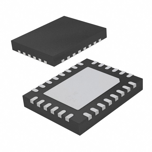
PD39210R-010020-TR is housed in a 32-pin, 5 mm × 5 mm QFN package with exposed thermal pad (ePAD) requiring connection to VSSA for thermal performance. The package is RoHS-compliant, MSL1 rated, and supports Pb-free reflow up to 260 °C.
| Pin/Terminal | Circuit Role | Design Meaning |
|---|---|---|
| 1, 2, 11, 12, 14, 17, 19 | Reserved | Unused pins; must be left open or pulled per datasheet (e.g., Pin 2 pulled to 3.3 V via 10 kΩ). |
| 3 (xSys_OK/LED System OK) | System Status Output | Active-low digital indicator of overall PSE health; drives LED or host GPIO without external logic. |
| 4 (xDISABLE_PORTS) | Global Port Shutdown Input | Active-low hardware kill switch; immediately disables all PoE ports regardless of firmware state. |
| 5–8 (ESPI_MISO/SCK/xCS/MOSI) | Manager Interface Bus | SPI slave interface to PD39208 manager; fixed 1 MHz clock; handles port control, telemetry, and fault reporting. |
| 13 (I2C_ADDR_MEAS) | Interface & Address Selector | Analog input setting I2C address (0x04–0x3C) or enabling UART mode; requires external resistor divider. |
| 15–16 (UART0_TX/RX) | Asynchronous Host Interface | Full-duplex UART at 19.2 kbps; used for configuration, diagnostics, and firmware updates independent of SPI manager. |
| 21–22 (I2C0_SDA/SCL) | Bidirectional I2C Host Interface | Standard I2C bus (400 kHz max); clock stretch support required; used for host-side monitoring and control. |
| 24 (xI2C_MESSAGE_READY) | I2C Polling Signal | Active-low handshake indicating valid data ready for host read; eliminates need for timed polling delays. |
| 25 (xINT_OUT) | Event Interrupt Output | Active-low interrupt signaling port faults, classification events, or power transitions; reduces host polling overhead. |
| 26 (xRESET) | Reset Control | Configurable bidirectional reset line: accepts active-low host reset and asserts self-reset pulse (100 µs low). |
| 29 (VDD_CORE) | Digital Core Supply | 1.2 V supply for ARM Cortex-M0+ core; requires local 1 µF decoupling to VSSD. |
| ePAD | Thermal & Electrical Ground | Must be soldered to VSSA plane with sufficient copper mass and thermal vias to maintain junction temp ≤100 °C. |
Key Features
| Feature | Design Value |
|---|---|
| Pre-programmed Firmware | Firmware vP2.xx pre-loaded; supports 802.3af/at natively; field-upgradable via I2C/UART; vendor-agnostic host compatibility. |
| Fast PoE Boot | Enables immediate port power-up after power-on without waiting for host initialization; reduces system startup latency. |
| Perpetual PoE (PPoE) | Maintains continuous PoE power delivery to connected PDs during host MCU firmware updates or reset cycles. |
| Legacy Detection | Supports pre-standard PDs using reduced-capacitance detection per port; ensures backward compatibility with older devices. |
| LED Stream Interface | Dedicated xLED_CS/xLED_OE/xLED_LATCH signals enable direct SPI-driven LED status indication for all 48 ports. |
Applications
| VoIP Phone Deployment | Enterprise Wireless Access Point |
|---|---|
|
Use Scenario: Powering 48-port VoIP phone switch in unified communications infrastructure. IC Role / Device Role / Timing Role: PD39210R-010020-TR performs IEEE 802.3af Class 2/3 detection, classification, and 15.4 W power enforcement per port. Use Value: Enables deterministic power allocation across all ports with per-system budgeting, reducing firmware complexity versus per-port management. |
Use Scenario: Midspan PoE injector powering dual-band 802.11ac access points in campus networks. IC Role / Device Role / Timing Role: PD39210R-010020-TR executes fast 2-pair power-up and maintains link integrity during AP firmware upgrades. Use Value: Perpetual PoE ensures uninterrupted Wi-Fi service during scheduled maintenance windows. |
| IP Security Camera Hub | Smart Building Sensor Gateway |
|
Use Scenario: Outdoor PoE switch powering 48 HD IP cameras with IR illumination and PTZ motors. IC Role / Device Role / Timing Role: PD39210R-010020-TR manages 30 W 2-pair delivery and monitors port current/voltage for overload protection. Use Value: Supports higher-power cameras requiring >15.4 W while maintaining IEEE 802.3at compliance and thermal safety. |
Use Scenario: Industrial gateway aggregating PoE-powered environmental sensors (temp, humidity, CO₂) in HVAC systems. IC Role / Device Role / Timing Role: PD39210R-010020-TR provides legacy detection for older sensor nodes and LED stream status feedback. Use Value: Simplifies commissioning and troubleshooting via real-time per-port LED indicators driven directly by the controller. |
Equivalent & Alternatives
The following parts are listed as comparable options for similar PoE PSE controller applications.
| Alternative Part | Technical Difference | Application Difference | Selection Advice |
|---|---|---|---|
| PD69210 | Full feature set: supports 802.3bt, HDBaseT, per-port power management, and 45 W 2-pair delivery. | Required for new designs needing 802.3bt Class 5–8 support or per-port dynamic power allocation. | Select PD69210 when future-proofing for higher-power PDs or advanced power negotiation protocols. |
| PD39210D1VVVV2SS3 | Same silicon and firmware baseline; differs only in packaging (tray vs. tape-and-reel) and trace code format. | No functional difference; identical electrical, thermal, and timing behavior in system design. | Choose PD39210D1VVVV2SS3 for manual prototyping or low-volume assembly; PD39210R-010020-TR preferred for automated SMT production. |
Compared with PD69210, PD39210R-010020-TR trades 802.3bt support and per-port power control for cost reduction and simplified firmware integration, while retaining full 802.3af/at compliance and 48-port scalability with PD39208.
Availability
PD39210R-010020-TR is available at Aetrix Electronics and suitable for enterprise networking equipment, industrial PoE switches, and smart building infrastructure requiring stable component supply, long-term lifecycle assurance, and RoHS-compliant manufacturing.
Supply support for PD39210R-010020-TR includes scheduled delivery planning, volume procurement assistance, BOM continuity management, traceable sourcing, and lifecycle availability coordination for OEM customers, industrial embedded developers, connected-device designers, and electronics production programs.
Manufacturer
Microchip Technology Inc. is a U.S.-based semiconductor manufacturer specializing in microcontrollers, analog, FPGA, and connectivity solutions, with a focus on embedded control and power management.
The PD39210R-010020-TR belongs to Microchip's Generation 6 PoE PSE controller family, engineered specifically for high-density, cost-optimized IEEE 802.3af/at power sourcing in managed switches and midspans.
FAQ
What IEEE standards does the PD39210R-010020-TR support?
The PD39210R-010020-TR supports IEEE 802.3af and 802.3at standards only. It does not support 802.3bt or HDBaseT (POH), as confirmed in the Features Matrix and Architecture sections of the official datasheet. This makes PD39210R-010020-TR suitable for Class 0–4 powered devices but excludes compatibility with higher-power Class 5–8 applications requiring 802.3bt.
How is the host interface selected on the PD39210R-010020-TR?
The host interface (I2C or UART) on the PD39210R-010020-TR is selected via analog voltage applied to pin #13 (I2C_ADDR_MEAS), using an external resistor divider. Specific resistor values determine both interface mode and I2C address (e.g., 147 kΩ selects UART mode; 86.6 kΩ sets I2C address 0x08). This configuration occurs at power-up and is latched internally.
Does the PD39210R-010020-TR support per-port power management?
No, the PD39210R-010020-TR implements per-system power management only, unlike the PD69210/PD69220 which support per-port power limiting. This means total system power is allocated centrally, and individual port overcurrent events trigger global responses unless handled externally by the PD39208 manager firmware.
What is the maximum power per port for the PD39210R-010020-TR?
The PD39210R-010020-TR supports up to 30 W per 2-pair port, as specified in the Features Matrix and Electrical Specifications. This is lower than the 45 W capability of PD69210/PD69220 and reflects its reduced feature set within the Generation 6 family. It remains fully compliant with IEEE 802.3at Type 2 (30 W) requirements.
Can the PD39210R-010020-TR operate without the PD39208 manager?
Yes, the PD39210R-010020-TR can operate in standalone mode using its pre-programmed firmware and default profiles. It supports direct I2C or UART communication with a host microcontroller for configuration and monitoring, eliminating dependency on the PD39208 manager in simpler, lower-port-count designs.
PD39210R-010020-TR Specifications
- Product attributes
- Attribute value
- Manufacturer:
- Microchip Technology
- Series:
- -
- Package/Case:
- 32-VFQFN Exposed Pad
- Packaging:
- Tape & Reel (TR)
- Product Status:
- Obsolete
- Type:
- Controller (PSE)
- Number of Channels:
- 48
- Power - Max:
- 30 W
- Internal Switch(s):
- No
- Auxiliary Sense:
- No
- Standards:
- 802.3at (PoE+), 802.3af (PoE)
- Voltage - Supply:
- 3V ~ 3.63V
- Current - Supply:
- -
- Operating Temperature:
- -40°C ~ 85°C (TA)
- Mounting Type:
- Surface Mount
- Supplier Device Package:
- 32-QFN (5x5)
PD39210R-010020-TR FAQ
1.How can I place an order for PD39210R-010020-TR through Aetrix?
Please submit a Request for Quotation (RFQ) for PD39210R-010020-TR on Aetrix. Our sales agent will provide a competitive quotation and guide you through the order confirmation once you accept the terms.
2.Are the price and stock information for PD39210R-010020-TR reliable?
The price and inventory of PD39210R-010020-TR are updated periodically and may fluctuate due to market conditions. Stock and pricing data are typically refreshed every 24 hours. Quotation validity for PD39210R-010020-TR is usually 5 days.
3.What payment methods are accepted for PD39210R-010020-TR?
We accept Wire Transfer, PayPal, Credit Card, Western Union, MoneyGram, and Escrow for PD39210R-010020-TR transactions.
Note: Certain payment methods may incur a processing fee.
4.How is shipping managed for PD39210R-010020-TR?
PD39210R-010020-TR orders can be shipped via leading logistics carriers, including DHL, UPS, FedEx, TNT, or Registered Mail.
Once your PD39210R-010020-TR order is processed, you will receive an email with the shipment details and tracking number.
Note: Tracking information may take up to 24 hours to appear. Express delivery typically takes 3–5 business days.
5.How can I obtain technical support or documentation for PD39210R-010020-TR?
For technical support, including PD39210R-010020-TR datasheets, pinout diagrams, or application guidance, please contact our engineering support team. They can provide detailed documentation and assistance for your PD39210R-010020-TR requirements.
6.How does Aetrix verify that PD39210R-010020-TR is sourced from the original manufacturer or authorized distributors?
All PD39210R-010020-TR products on Aetrix are procured from qualified distributors and authorized channels. Our dedicated quality assurance team conducts strict verification, including traceability checks and, if necessary, third-party testing. This ensures that PD39210R-010020-TR meets industry standards.
7.What is the process for return or replacement of PD39210R-010020-TR?
All PD39210R-010020-TR units undergo pre-shipment inspection (PSI). If there is an issue with PD39210R-010020-TR, returns or replacements are accepted under the following conditions:
1.Quantity discrepancies, incorrect items, or visible external defects (such as breakage or corrosion), acknowledged by Aetrix.
2.The issue is reported within 90 days of delivery.
3.The PD39210R-010020-TR part is unused and in its original packaging.
Return procedure for PD39210R-010020-TR:
1.Submit a request within 90 days.
2.Obtain a Return Material Authorization (RMA) from Aetrix.
PD39210R-010020-TR Tags

-
TPS2378DDAR
Texas Instruments
-
TPS23753APWR
Texas Instruments
-
TPS23756PWPR
Texas Instruments
-
TPS23750PWPR
Texas Instruments
-
MP8007GV-Z
Monolithic Power Systems Inc.
-
TPS23861PWR
Texas Instruments

-
TPS23753PWR
Texas Instruments
-
PD69201ILD-TR
Microchip Technology
-
SI3402-B-GM
Skyworks Solutions Inc.
-
SI3402-B-GMR
Skyworks Solutions Inc.
-
SI34071-A01-GMR
Skyworks Solutions Inc.
-
SI3404-A-GMR
Skyworks Solutions Inc.
Tech Hub

TTL and CMOS logic families differ in thresholds, loading, output drive, power and timing. This engineering guide compares 74HC and 74HCT, calculates noise margins and checks 3.3 V/5 V compatibility.

A practical engineering guide to 3.3V and 5V logic compatibility, input thresholds, resistor dividers, translator ICs, MOSFET level shifting, I2C pull-ups, timing limits and power-sequencing risks.

The 74HC595 uses push-pull logic outputs, while the TPIC6B595 uses 50 V open-drain DMOS sinks for higher-power loads. This guide compares timing, current limits, 3.3 V interfacing, load wiring, thermal…

The 74HC595 converts serial data into eight stable parallel outputs. This guide covers pin functions, shift and storage timing, OE and MR behavior, drive-current limits, cascading, voltage compatibilit…

A technical comparison of level-sensitive latches and edge-triggered flip-flops, covering timing windows, setup and hold limits, master–slave operation, time borrowing, race-through, HDL inference and…

A D latch stores one bit while Enable controls when data can pass. This reference covers gate-level operation, truth tables, transparency, setup and hold timing, LE versus OE, common ICs and practical …

An SR latch stores one bit through cross-coupled feedback. This engineering reference covers NOR and NAND implementations, truth tables, forbidden-state recovery, gated operation, switch debouncing, fa…

Latch circuits retain one bit through feedback. This technical reference covers SR and D latches, truth tables, transparency, timing limits, latch-versus-flip-flop behavior, applications and common log…

An engineering guide to LED driver operation, constant-current and constant-voltage outputs, linear and switching topologies, dimming, IC selection, calculations, replacement compatibility, and fault c…

Operational amplifier guide covering op amp basics, feedback, ideal vs real op amps, common configurations, buffer circuits, offset, bias current, gain-bandwidth, slew rate, rail-to-rail limits and sel…


