
 My Inquiry
 My Account


Microchip Technology PD69200R-017223
- Part No.:
- PD69200R-017223
- Manufacturer:
- Microchip Technology
- Category:
- Power Over Ethernet (PoE) Controllers
- Package:
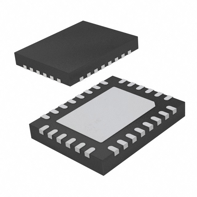
- 32-VFQFN Exposed Pad
- Datasheet:
-
 PD69200R-017223.pdf
- Description:
- MCU
- Quantity:
- Payment:

- Shipping:

Inventory:4,393
Please send an inquiry. Send us your inquiry, and we will respond immediately.
Product details
Overview
PD69200R-017223 from Microchip Technology is a Power over Ethernet (PoE) Power Sourcing Equipment (PSE) controller IC designed to manage IEEE 802.3af/at/bt and HDBaseT (PoH) compliant power delivery across up to 48 logical ports via cascaded PoE managers. It integrates an NXP MKL15Z128VFM4-based core, supports 45 W two-pair and 90 W four-pair per port, operates from a 3.3 V supply, and resides in a 32-pin 5 mm × 5 mm QFN package. It enables intelligent power classification, dynamic/legacy detection, and system-level event reporting in enterprise switches and midspan injectors.
For engineers reviewing the PD69200R-017223 datasheet, PD69200R-017223 pinout, PD69200R-017223 application, or PD69200R-017223 equivalent, key selection criteria include IEEE 802.3bt compliance, SPI/I2C/UART host interface flexibility, 32-pin QFN thermal performance, firmware-upgradability, and compatibility with PD69208T4/PD69204T4/PD69208M PoE managers.
Technical Context
The PD69200R-017223 implements a hierarchical PSE architecture where it acts as the central intelligence layer-communicating with up to 12 PoE manager ICs (e.g., PD69208T4) via 1 MHz SPI-and coordinating port power allocation, priority, and fault handling. Its firmware supports three power management modes (Class, Dynamic, Static), 16 independent power banks, and real-time port measurements including voltage, current, and temperature.
Hardware interfaces include UART (19.2 kbps, 15-byte protocol), I2C (400 kHz with clock stretch support), and dedicated control pins for LED streaming, fan control, system OK indication, and port disable. Pin #22 (I2C_ADDR_MEAS) configures both communication interface selection (UART vs. I2C) and 7-bit I2C address via external resistor ladder.
Key Specifications
| Parameter | Value and Actual Design Meaning |
|---|---|
| Standards Compliance | IEEE 802.3af, 802.3at, 802.3bt, and HDBaseT (PoH) - enables full interoperability with Class 0–8 PDs and 90 W four-pair operation. |
| Max Port Power | 45 W (two-pair), 90 W (four-pair) - supports high-power devices like PTZ cameras, thin clients, and wireless APs without external boost stages. |
| Supply Voltage | 3.0–3.63 V (VDD/VDDA) - compatible with standard 3.3 V system rails; requires separate analog/digital ground planes (VSSA/VSSD). |
| Package | 32-pin QFN, 5 mm × 5 mm, 0.5 mm pitch - provides low thermal resistance (θJA = 33 °C/W) and supports high-density PoE switch PCB layouts. |
| Interface Options | UART (19.2 kbps), I2C (400 kHz w/ clock stretch), SPI (1 MHz master-to-manager) - allows flexible host integration without requiring dedicated high-speed peripherals. |
| ESD Rating | HBM ±2000 V, CDM ±500 V - meets industrial-grade robustness requirements for field-deployable networking equipment. |
| Operating Temp | −40 °C to +85 °C - qualified for uncontrolled environment deployments in telecom cabinets and outdoor enclosures. |
Pinout & Package
PD69200R-017223 is housed in a 32-pin, 5 mm × 5 mm QFN package with exposed thermal pad (ePAD) requiring connection to VSSA. The package complies with MSL3, RoHS, and Pb-free reflow profiles (peak 260 °C).
| Pin/Terminal | Circuit Role | Design Meaning |
|---|---|---|
| 1–2, 9, 14, 17–18, 23, 29 | Reserved / Analog_IN / Oscillator | Unused or factory-configured functions; pins 9/14/29 require tie-high/tie-low per datasheet; oscillator pins must be left open. |
| 3–6 (ESPI_xCS, ESPI_SCK, ESPI_MOSI, ESPI_MISO) | SPI Interface to PoE Managers | Controls up to 12 PD69208T4/PD69204T4/PD69208M managers; 1 MHz clock, active-low chip select, full-duplex data path. |
| 7 (VDDA), 15 (VDD), ePAD | Analog/Digital Supply & Thermal Pad | VDDA powers analog circuitry (ADC, comparators); VDD powers digital logic; ePAD must connect to VSSA with ≥65% solder coverage for thermal integrity. |
| 11–12 (UART0_RX, UART0_TX), 20–21 (I2C0_SCL, I2C0_SDA) | Host Communication Interfaces | Dual-interface capability: UART uses 15-byte command/reply protocol; I2C requires clock stretch support and pull-ups; pin #22 selects mode and address. |
| 24–28 (xI2C_MESSAGE_READY, xINT_OUT, xLED_CS, xLED_LATCH, xLED_OE) | System Event & LED Control | xINT_OUT signals preconfigured events (e.g., overload, disconnect); LED control pins drive serial LED streams for port status visualization. |
| 30 (FAN_CONTROL), 31 (xDISABLE_PORTS), 32 (xSys_OK/LED) | System Management | FAN_CONTROL drives external fan drivers (active-high); xDISABLE_PORTS shuts down all PoE ports (active-low); xSys_OK indicates system validity (active-low, software-maskable). |
Key Features
| Feature | Design Value |
|---|---|
| IEEE 802.3bt & PoH Support | Enables 90 W four-pair power delivery and HDBaseT compatibility-critical for powering high-end AV-over-IP endpoints without proprietary extensions. |
| 16-Power-Bank Architecture | Allows granular allocation of up to four independent 48 V supplies across logical ports, supporting mixed-class deployments and redundancy schemes. |
| Firmware Upgradability | Field updates via UART or I2C eliminate hardware revisions-enabling new feature rollouts (e.g., enhanced diagnostics, updated safety algorithms) post-deployment. |
| Legacy Detection & Fast PoE | Supports pre-standard PDs while maintaining fast classification (<300 ms), reducing boot time in legacy infrastructure upgrades. |
| LED Stream Interface | Serial LED control (CS/LATCH/OE) reduces GPIO count and simplifies multi-port status indication-eliminates need for external LED drivers or shift registers. |
| Port Matrix & Priority Engine | Hardware-accelerated port grouping and priority arbitration ensures deterministic power allocation during overload conditions-prevents non-critical ports from starving critical ones. |
Applications
| Enterprise Switch PSE | Midspan PoE Injector |
|---|---|
|
Use Scenario: 24- or 48-port managed Ethernet switch delivering PoE to VoIP phones, wireless access points, and security cameras. IC Role / Device Role / Timing Role: Central PSE controller managing up to 48 logical ports via cascaded PD69208T4 managers; coordinates classification, power ramp, and fault recovery. Use Value: Enables IEEE 802.3bt compliance and 90 W per port without redesigning power stage-reducing BOM cost versus discrete controller + FET solutions. |
Use Scenario: Standalone 8- or 16-port midspan injector adding PoE capability to legacy non-PoE switches. IC Role / Device Role / Timing Role: Standalone PSE intelligence layer interfacing directly with host MCU via UART/I2C; handles detection, classification, and power enforcement per port. Use Value: Eliminates need for custom firmware development-pre-integrated stack supports Class 0–8, LLDP, and dynamic power management out-of-box. |
| Industrial IoT Gateway | Smart Building Controller |
|
Use Scenario: Ruggedized gateway aggregating sensors, actuators, and edge AI nodes powered via PoE in factory automation environments. IC Role / Device Role / Timing Role: PSE controller integrated into gateway's main board; manages power to connected PoE-powered PLCs, cameras, and gateways with thermal monitoring. Use Value: Supports −40 °C to +85 °C operation and HBM ±2000 V ESD-ensuring reliability in electrically noisy industrial settings. |
Use Scenario: Central building controller powering IP intercoms, door controllers, occupancy sensors, and lighting nodes over structured cabling. IC Role / Device Role / Timing Role: Embedded PSE controller enabling centralized power budgeting, remote port enable/disable, and energy usage telemetry via I2C-hosted API. Use Value: Provides real-time port current/voltage measurement and configurable power limits-supporting demand-response and predictive maintenance workflows. |
Equivalent & Alternatives
The following parts are listed as comparable options for similar PoE PSE controller applications.
| Alternative Part | Technical Difference | Application Difference | Selection Advice |
|---|---|---|---|
| PD69220 | Pin-compatible with identical feature set; based on Microchip SAM D21 instead of NXP Kinetis L; newer firmware baseline and extended lifecycle support. | Recommended for new designs due to ongoing roadmap support; PD69200 remains valid for legacy design continuity and firmware reuse. | Select PD69220 for greenfield projects requiring long-term availability and latest firmware features; retain PD69200 only for exact drop-in replacement in existing production. |
| PD69210 | Based on SAM D21 but lacks pin compatibility with PD69200; different pinout and reduced peripheral set (no LED stream, no FAN_CONTROL, fewer interrupt options). | Targeted at cost-optimized, lower-port-count systems; not suitable for designs relying on PD69200-specific interfaces or LED control. | Choose PD69210 only when port count ≤16 and LED/fan control are unnecessary-avoid if migrating from PD69200 without PCB revision. |
Compared with PD69220 and PD69210, the PD69200R-017223 offers guaranteed pin and firmware compatibility with deployed PD69200-based systems, full LED stream and fan control support, and seamless integration with legacy NXP-based toolchains-making it the sole option for sustaining production of existing IEEE 802.3bt-compliant PSE hardware.
Availability
PD69200R-017223 is available at Aetrix Electronics and suitable for enterprise switching, midspan PoE injection, industrial IoT gateways, and smart building controllers requiring stable component supply, long-lifecycle assurance, and full IEEE 802.3bt compliance.
Supply support for PD69200R-017223 includes scheduled delivery planning, volume procurement assistance, BOM continuity management, traceable sourcing, and lifecycle availability coordination for OEM customers, industrial embedded developers, connected-device designers, and electronics production programs.
Manufacturer
Microchip Technology Inc. is a global provider of microcontrollers, analog, FPGA, and connectivity solutions, serving automotive, industrial, communications, and computing markets with vertically integrated silicon and software.
The PD69200R-017223 belongs to Microchip's PoE PSE Controller product line, engineered specifically to simplify implementation of multi-port, standards-compliant Power over Ethernet systems-targeting switch vendors, infrastructure OEMs, and system integrators needing turnkey power management.
FAQ
What is the primary function of the PD69200R-017223 in a PoE system?
The PD69200R-017223 serves as the central Power Sourcing Equipment (PSE) controller IC in IEEE 802.3af/at/bt and HDBaseT-compliant PoE systems. It manages up to 48 logical ports by coordinating with PD69208T4/PD69204T4/PD69208M PoE managers via SPI, executing detection, classification, power application, and fault monitoring-all while supporting dynamic power allocation, port prioritization, and real-time telemetry. Its role is strictly control-layer intelligence-not power switching.
Does the PD69200R-017223 integrate power MOSFETs or require external PoE power stages?
No, the PD69200R-017223 does not integrate power MOSFETs or DC-DC converters. It is a pure controller IC that must be paired with external PoE manager ICs (e.g., PD69208T4) and discrete power FETs or integrated PoE power modules. Its function is to generate control signals, monitor port parameters, and enforce IEEE-compliant power sequencing-leaving power delivery hardware to companion components.
How is firmware updated on the PD69200R-017223, and what interfaces support this?
Firmware on the PD69200R-017223 is field-upgradable exclusively via its UART or I2C interface using Microchip's 15-byte protocol. The device ships with pre-programmed firmware identifiable by ordering part number suffixes (VVVV/SS). Host MCU-initiated updates require no JTAG/SWD access-only UART TX/RX or I2C SCL/SDA connections and proper pull-up configuration. SPI is reserved for manager communication and cannot be used for firmware loading.
Can the PD69200R-017223 operate standalone without a host microcontroller?
Yes, the PD69200R-017223 can operate in standalone mode using its internal default profiles for port power limits, classification, and priority. It does not require continuous host supervision. However, host interaction (via UART/I2C) is necessary for advanced functions such as dynamic power adjustment, LED stream configuration, firmware updates, or reading real-time port measurements-standalone mode supports basic IEEE-compliant operation only.
What thermal design considerations apply to the PD69200R-017223's QFN package?
The PD69200R-017223's 32-pin QFN package features an exposed thermal pad (ePAD) that must be soldered to a dedicated VSSA copper plane with ≥65% solder coverage and multiple thermal vias. Its junction-to-ambient thermal resistance (θJA) is 33 °C/W, so PCB layout must allocate ≥200 mm² of inner-layer copper connected to the ePAD. Avoid routing signal traces under the package and ensure the thermal pad connects only to ground-not to power or signal nets-to maintain noise immunity and thermal efficiency.
PD69200R-017223 Specifications
- Product attributes
- Attribute value
- Manufacturer:
- Microchip Technology
- Series:
- -
- Package/Case:
- 32-VFQFN Exposed Pad
- Packaging:
- Bulk
- Product Status:
- Obsolete
- Type:
- Controller (PSE)
- Number of Channels:
- 48
- Power - Max:
- 90 W
- Internal Switch(s):
- No
- Auxiliary Sense:
- Yes
- Standards:
- 802.3at (PoE+), 802.3af (PoE), 802.3bt
- Voltage - Supply:
- 3V ~ 3.63V
- Current - Supply:
- -
- Operating Temperature:
- -40°C ~ 85°C (TA)
- Mounting Type:
- Surface Mount
- Supplier Device Package:
- 32-QFN (5x5)
PD69200R-017223 FAQ
1.How can I place an order for PD69200R-017223 through Aetrix?
Please submit a Request for Quotation (RFQ) for PD69200R-017223 on Aetrix. Our sales agent will provide a competitive quotation and guide you through the order confirmation once you accept the terms.
2.Are the price and stock information for PD69200R-017223 reliable?
The price and inventory of PD69200R-017223 are updated periodically and may fluctuate due to market conditions. Stock and pricing data are typically refreshed every 24 hours. Quotation validity for PD69200R-017223 is usually 5 days.
3.What payment methods are accepted for PD69200R-017223?
We accept Wire Transfer, PayPal, Credit Card, Western Union, MoneyGram, and Escrow for PD69200R-017223 transactions.
Note: Certain payment methods may incur a processing fee.
4.How is shipping managed for PD69200R-017223?
PD69200R-017223 orders can be shipped via leading logistics carriers, including DHL, UPS, FedEx, TNT, or Registered Mail.
Once your PD69200R-017223 order is processed, you will receive an email with the shipment details and tracking number.
Note: Tracking information may take up to 24 hours to appear. Express delivery typically takes 3–5 business days.
5.How can I obtain technical support or documentation for PD69200R-017223?
For technical support, including PD69200R-017223 datasheets, pinout diagrams, or application guidance, please contact our engineering support team. They can provide detailed documentation and assistance for your PD69200R-017223 requirements.
6.How does Aetrix verify that PD69200R-017223 is sourced from the original manufacturer or authorized distributors?
All PD69200R-017223 products on Aetrix are procured from qualified distributors and authorized channels. Our dedicated quality assurance team conducts strict verification, including traceability checks and, if necessary, third-party testing. This ensures that PD69200R-017223 meets industry standards.
7.What is the process for return or replacement of PD69200R-017223?
All PD69200R-017223 units undergo pre-shipment inspection (PSI). If there is an issue with PD69200R-017223, returns or replacements are accepted under the following conditions:
1.Quantity discrepancies, incorrect items, or visible external defects (such as breakage or corrosion), acknowledged by Aetrix.
2.The issue is reported within 90 days of delivery.
3.The PD69200R-017223 part is unused and in its original packaging.
Return procedure for PD69200R-017223:
1.Submit a request within 90 days.
2.Obtain a Return Material Authorization (RMA) from Aetrix.
PD69200R-017223 Tags

-
TPS2378DDAR
Texas Instruments
-
TPS23753APWR
Texas Instruments
-
TPS23756PWPR
Texas Instruments
-
TPS23750PWPR
Texas Instruments
-
MP8007GV-Z
Monolithic Power Systems Inc.
-
TPS23861PWR
Texas Instruments

-
TPS23753PWR
Texas Instruments
-
PD69201ILD-TR
Microchip Technology
-
SI3402-B-GM
Skyworks Solutions Inc.
-
SI3402-B-GMR
Skyworks Solutions Inc.
-
SI34071-A01-GMR
Skyworks Solutions Inc.
-
SI3404-A-GMR
Skyworks Solutions Inc.
Tech Hub

TTL and CMOS logic families differ in thresholds, loading, output drive, power and timing. This engineering guide compares 74HC and 74HCT, calculates noise margins and checks 3.3 V/5 V compatibility.

A practical engineering guide to 3.3V and 5V logic compatibility, input thresholds, resistor dividers, translator ICs, MOSFET level shifting, I2C pull-ups, timing limits and power-sequencing risks.

The 74HC595 uses push-pull logic outputs, while the TPIC6B595 uses 50 V open-drain DMOS sinks for higher-power loads. This guide compares timing, current limits, 3.3 V interfacing, load wiring, thermal…

The 74HC595 converts serial data into eight stable parallel outputs. This guide covers pin functions, shift and storage timing, OE and MR behavior, drive-current limits, cascading, voltage compatibilit…

A technical comparison of level-sensitive latches and edge-triggered flip-flops, covering timing windows, setup and hold limits, master–slave operation, time borrowing, race-through, HDL inference and…

A D latch stores one bit while Enable controls when data can pass. This reference covers gate-level operation, truth tables, transparency, setup and hold timing, LE versus OE, common ICs and practical …

An SR latch stores one bit through cross-coupled feedback. This engineering reference covers NOR and NAND implementations, truth tables, forbidden-state recovery, gated operation, switch debouncing, fa…

Latch circuits retain one bit through feedback. This technical reference covers SR and D latches, truth tables, transparency, timing limits, latch-versus-flip-flop behavior, applications and common log…

An engineering guide to LED driver operation, constant-current and constant-voltage outputs, linear and switching topologies, dimming, IC selection, calculations, replacement compatibility, and fault c…

Operational amplifier guide covering op amp basics, feedback, ideal vs real op amps, common configurations, buffer circuits, offset, bias current, gain-bandwidth, slew rate, rail-to-rail limits and sel…


