
 My Inquiry
 My Account


STMicroelectronics PEP01-5841
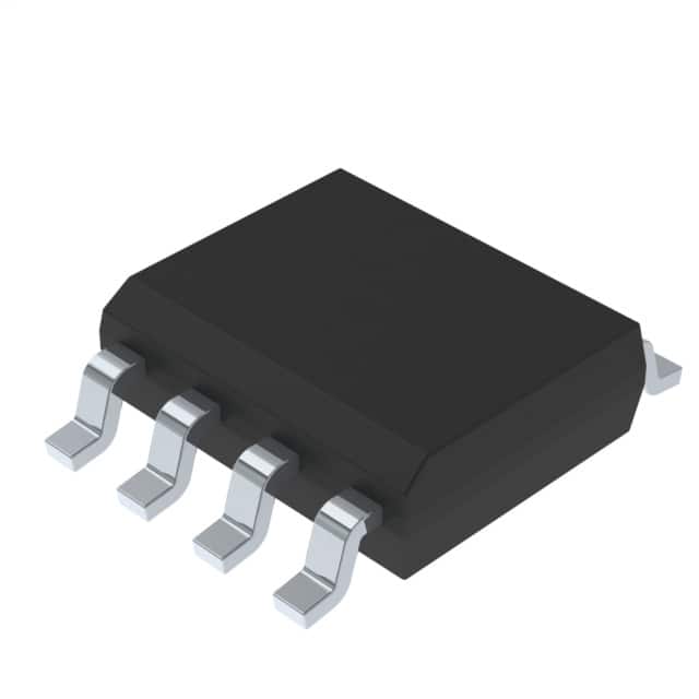
- Part No.:
- PEP01-5841
- Manufacturer:
- STMicroelectronics
- Category:
- Thyristors
- Package:
- 8-SOIC (0.154", 3.90mm Width)
- Datasheet:
-
 PEP01-5841.pdf
- Description:
- THYRISTOR 24A 8-SOIC
- Quantity:
- Payment:

- Shipping:

Inventory:6,610
Please send an inquiry. Send us your inquiry, and we will respond immediately.
Product details
Overview
PEP01-5841 from STMicroelectronics is a quad unidirectional TVS diode array in SO-8 package, designed specifically for overvoltage protection of Power over Ethernet (PoE) power sourcing equipment (PSE). It features 58 V stand-off voltage, 100 V clamping voltage at 24 A, 2.7 kW peak pulse power (8/20 μs), and integrates four 55 pF decoupling capacitors per channel for supply stabilization in IEEE 802.3af/at-compliant systems.
For engineers reviewing the PEP01-5841 datasheet, PEP01-5841 pinout, PEP01-5841 application, or PEP01-5841 equivalent, this device addresses PoE PSE front-end surge immunity (IEC61000-4-2 ±15 kV air / ±8 kV contact; IEC61000-4-5 level 2 ±1 kV), low-leakage operation (0.2 μA @ 25 °C), and compatibility with PMOS-based PSE controllers requiring tight clamping headroom.
Technical Context
The PEP01-5841 implements four independent unidirectional Transil structures in a single SO-8 package, each with integrated 55 pF decoupling capacitance to suppress high-frequency noise on PoE power lines. Its planar silicon technology ensures stable breakdown behavior across –55 °C to +150 °C junction temperature range.
It operates as a primary-level transient suppressor between the PSE controller and external PMOS switch or integrated PMOS output stage, clamping surges before they reach sensitive gate drivers. The COM pins (2, 3, 6, 7) are internally tied to substrate and must be externally connected to system ground to ensure proper thermal dissipation and ESD current return path integrity.
Key Specifications
| Parameter | Value and Actual Design Meaning |
|---|---|
| Stand-off Voltage (VRM) | 58 V - Maximum continuous DC operating voltage before leakage exceeds 0.2 μA; sets PoE 48 V supply margin. |
| Clamping Voltage (VCL) | 100 V at 24 A (8/20 μs) - Limits transient voltage seen by downstream PMOS gate driver during IEC61000-4-5 surges. |
| Peak Pulse Power | 2.7 kW - Sustains IEEE 802.3at PoE+ surge events without degradation under specified waveform and thermal conditions. |
| Decoupling Capacitance | 55 pF per channel - Filters high-frequency noise on PoE power rails; eliminates need for discrete bypass caps in compact PSE layouts. |
| Leakage Current | 0.2 μA @ 25 °C - Ensures minimal standby power loss and avoids false triggering in always-on PSE detection circuitry. |
| Junction Temp Range | –55 °C to +150 °C - Supports industrial-grade PoE switches operating in enclosed, thermally constrained environments. |
Pinout & Package
PEP01-5841 is housed in a JEDEC-registered SO-8 package (4.9 mm × 6.0 mm × 1.25 mm height), compliant with IPC-7531 footprint standards and optimized for high-voltage clearance (>50 V) via extended pad spacing.
| Pin/Terminal | Circuit Role | Design Meaning |
|---|---|---|
| PS1 | Protected Supply Line 1 Anode | Input node for first PoE power pair; connects to PSE output before PMOS switch. |
| COM | Common Cathode / Ground Reference | Pins 2, 3, 6, 7 are internally bonded cathodes; all must be soldered to PCB ground plane for thermal and ESD return path. |
| PS2 | Protected Supply Line 2 Anode | Input node for second PoE power pair; enables simultaneous protection of dual-class PSE outputs. |
| PS3 | Protected Supply Line 3 Anode | Third protected line; supports multi-port PSE designs with up to four independent power channels. |
| PS4 | Protected Supply Line 4 Anode | Fourth protected line; matches IEEE 802.3bt 4-pair PoE architecture requirements. |
Key Features
| Feature | Design Value |
|---|---|
| Integrated Decoupling Capacitance | 55 pF per channel reduces board area and parasitic inductance vs. discrete capacitor + TVS solutions. |
| Low Clamping Voltage | 100 V clamping at 24 A ensures safe operation with 100 V-rated PMOS FETs used in modern PSE controllers. |
| Quad Unidirectional Architecture | Four independent anode-to-common-cathode paths enable isolated protection of multiple PoE power pairs without cross-talk. |
| High-Temperature Reliability | Rated for 150 °C junction operation and qualified per JEDEC JESD22-A108; suitable for sealed PoE switch enclosures. |
Applications
| IEEE 802.3af/at PSE Controllers | Multi-Port PoE Switches |
|---|---|
Use Scenario: Protection of integrated PMOS outputs in single-chip PSE controllers such as ST's TCPP01-M12 or similar. IC Role / Device Role / Timing Role: Primary transient voltage suppressor placed directly at PMOS drain node to clamp IEC61000-4-5 surges before gate driver damage. Use Value: Eliminates need for external RC snubbers and reduces BOM count by integrating 55 pF capacitance per channel. | Use Scenario: Front-end surge protection for 8- or 16-port enterprise PoE switches with distributed PSE circuitry. IC Role / Device Role / Timing Role: Channel-isolated TVS array ensuring independent protection of each powered pair without shared impedance coupling. Use Value: Enables compact layout with minimized trace length between PEP01-5841 and PMOS devices, preserving signal integrity and surge response time. |
| Industrial PoE Injectors | Outdoor PoE Extenders |
Use Scenario: DIN-rail mounted PoE injectors deployed in factory automation with high ambient temperature and EMI exposure. IC Role / Device Role / Timing Role: High-reliability overvoltage guard for 48 V DC input stage exposed to load dump and lightning-induced transients. Use Value: 150 °C max junction rating and 2.7 kW pulse handling support continuous operation in uncooled enclosures. | Use Scenario: Weatherproof outdoor PoE extenders powering wireless access points or security cameras over long cable runs. IC Role / Device Role / Timing Role: Dual-stage protector-first line of defense against induced surges from nearby lightning strikes on Ethernet cabling. Use Value: ±15 kV air discharge ESD rating prevents field failures in humid, high-static environments without additional shielding. |
Equivalent & Alternatives
The following parts are listed as comparable options for similar PoE PSE protection applications.
| Alternative Part | Technical Difference | Application Difference | Selection Advice |
|---|---|---|---|
| SMAJ58A | Single-channel 58 V TVS; no integrated capacitance; SO-204 package. | Requires four discrete devices plus external 55 pF caps per channel; larger PCB footprint. | Use only when cost-per-channel is prioritized over layout density and assembly complexity. |
| SP1003-058 | Quad bidirectional TVS; 58 V standoff; 100 V clamping; no integrated capacitance. | Lacks decoupling capacitance; requires external filtering; bidirectional conduction may interfere with PSE polarity detection. | Select only if system design mandates symmetric surge suppression on both data and power lines. |
Compared with SMAJ58A and SP1003-058, PEP01-5841 uniquely combines quad unidirectional protection, integrated 55 pF capacitance per channel, and SO-8 packaging-reducing component count by ≥50%, minimizing parasitic inductance, and enabling direct placement at PMOS drain nodes in space-constrained PSE modules.
Availability
PEP01-5841 is available at Aetrix Electronics and suitable for IEEE 802.3af/at PSE controller designs, multi-port PoE switches, and industrial PoE injectors requiring stable component supply, long-term lifecycle assurance, and RoHS-compliant ECOPACK packaging.
Supply support for PEP01-5841 includes scheduled delivery planning, volume procurement assistance, BOM continuity management, traceable sourcing, and lifecycle availability coordination for OEM customers, industrial embedded developers, connected-device designers, and electronics production programs.
Manufacturer
STMicroelectronics is a global semiconductor leader headquartered in Geneva, Switzerland, specializing in automotive, industrial, and power management ICs with strong IP in protection devices and analog front-ends.
PEP01-5841 belongs to ST's Power Over Ethernet Protection portfolio, engineered specifically to meet IEEE 802.3af/at surge immunity requirements while simplifying PSE board layout through integrated capacitance and quad-channel integration.
FAQ
What is the maximum peak pulse current the PEP01-5841 can handle?
The PEP01-5841 sustains 24 A peak pulse current (8/20 μs waveform) at 100 V clamping voltage, corresponding to its 2.7 kW peak pulse power rating. This value is validated per IEC61000-4-5 level 2 testing conditions and remains stable up to 150 °C junction temperature, as confirmed in DS6245 Rev 5 Figure 5.
Can the COM pins be left floating or partially connected?
No. Pins 2, 3, 6, and 7 are internally connected cathodes and must all be soldered to a low-impedance PCB ground plane. Floating or partial connection degrades clamping performance, increases thermal resistance, and risks catastrophic failure during surge events due to uncontrolled current return paths.
Does the integrated 55 pF capacitance affect high-speed Ethernet data integrity?
No. The 55 pF capacitance is placed only on the DC power lines (not data pairs), and its frequency roll-off begins above 10 MHz-well beyond the 100 MHz bandwidth of 100BASE-TX and 1 GbE signals. ST confirms no impact on MDI signal integrity in application note AN4778.
Is PEP01-5841 compatible with IEEE 802.3bt (PoE++) systems?
Yes, for Type 3 (60 W) applications. Its 58 V standoff and 100 V clamping align with the higher voltage margins required by 802.3bt PSE stages. However, for Type 4 (90 W) systems using 57 V nominal, verify system-level clamping headroom with PSE controller VDS(max) ratings, as 100 V clamping leaves <3 V margin at 97 V surge peaks.
PEP01-5841 Specifications
- Product attributes
- Attribute value
- Manufacturer:
- STMicroelectronics
- Package/Case:
- 8-SOIC (0.154", 3.90mm Width)
- Series:
- PEP, TRANSIL™
- Packaging:
- Tape & Reel (TR)
- Product Status:
- Active
- Voltage - Breakover:
- -
- Voltage - Off State:
- -
- Voltage - On State:
- -
- Current - Peak Pulse (8/20µs):
- 24 A
- Current - Peak Pulse (10/1000µs):
- -
- Current - Hold (Ih):
- -
- Number of Elements:
- 4
- Capacitance:
- 55pF
- Grade:
- -
- Qualification:
- -
- Mounting Type:
- Surface Mount
- Supplier Device Package:
- 8-SOIC
PEP01-5841 FAQ
1.How can I place an order for PEP01-5841 through Aetrix?
Please submit a Request for Quotation (RFQ) for PEP01-5841 on Aetrix. Our sales agent will provide a competitive quotation and guide you through the order confirmation once you accept the terms.
2.Are the price and stock information for PEP01-5841 reliable?
The price and inventory of PEP01-5841 are updated periodically and may fluctuate due to market conditions. Stock and pricing data are typically refreshed every 24 hours. Quotation validity for PEP01-5841 is usually 5 days.
3.What payment methods are accepted for PEP01-5841?
We accept Wire Transfer, PayPal, Credit Card, Western Union, MoneyGram, and Escrow for PEP01-5841 transactions.
Note: Certain payment methods may incur a processing fee.
4.How is shipping managed for PEP01-5841?
PEP01-5841 orders can be shipped via leading logistics carriers, including DHL, UPS, FedEx, TNT, or Registered Mail.
Once your PEP01-5841 order is processed, you will receive an email with the shipment details and tracking number.
Note: Tracking information may take up to 24 hours to appear. Express delivery typically takes 3–5 business days.
5.How can I obtain technical support or documentation for PEP01-5841?
For technical support, including PEP01-5841 datasheets, pinout diagrams, or application guidance, please contact our engineering support team. They can provide detailed documentation and assistance for your PEP01-5841 requirements.
6.How does Aetrix verify that PEP01-5841 is sourced from the original manufacturer or authorized distributors?
All PEP01-5841 products on Aetrix are procured from qualified distributors and authorized channels. Our dedicated quality assurance team conducts strict verification, including traceability checks and, if necessary, third-party testing. This ensures that PEP01-5841 meets industry standards.
7.What is the process for return or replacement of PEP01-5841?
All PEP01-5841 units undergo pre-shipment inspection (PSI). If there is an issue with PEP01-5841, returns or replacements are accepted under the following conditions:
1.Quantity discrepancies, incorrect items, or visible external defects (such as breakage or corrosion), acknowledged by Aetrix.
2.The issue is reported within 90 days of delivery.
3.The PEP01-5841 part is unused and in its original packaging.
Return procedure for PEP01-5841:
1.Submit a request within 90 days.
2.Obtain a Return Material Authorization (RMA) from Aetrix.
PEP01-5841 Tags
-
TISP4015L1AJR-S
Bourns Inc.
-
TISP4015L1BJR-S
Bourns Inc.
-
SMP100LC-270
STMicroelectronics
-
TISP4240M3BJR-S
Bourns Inc.
-
SMP100LC-35
STMicroelectronics
-
SMP100LC-65
STMicroelectronics
-
SMP100LC-8
STMicroelectronics
-
TISP4P035L1NR-S
Bourns Inc.
-
TISP4350H3BJR-S
Bourns Inc.
-
TISP4011H1BJR-S
Bourns Inc.
-
SMP100LC-400
STMicroelectronics
-
P0300SALRP
Littelfuse Inc.
Tech Hub

Jumper cables guide covering safe connection order, red and black clamp placement, final ground connection, cable gauge, length, clamp quality, copper vs CCA cables, jump starter comparison and battery…

LDO regulator guide covering low dropout voltage, power dissipation, thermal design, PSRR, output noise, capacitor stability, adjustable LDO circuits, LDO vs buck converter and datasheet selection chec…

Conditional Access Module guide covering CAM meaning, CI/CI+ interface, smart card authorization, DVB security workflow, TV and set-top box compatibility, internal electronics, ESD protection, connecto…

Guide to electronic component obsolescence covering EOL risk, PCN/PDN notices, last-time buy planning, replacement options, form-fit-function validation, counterfeit risk and BOM lifecycle management.

18650 battery guide covering lithium-ion cell basics, 3.6V/3.7V voltage, 4.2V charging, mAh and Wh capacity, protected cells, chargers, BMS, series-parallel packs, holders, welding and sourcing checks.…

Hall effect sensor guide covering working principle, linear and digital sensors, Arduino circuits, current sensing, speed detection, automotive applications, A3144 examples, signal filtering and datash…

Product Change Notification guide for electronic components, covering PCN meaning, PCN vs PDN/EOL, common change types, risk levels, form-fit-function review, engineering validation, BOM control, LTB/L…

A practical guide to blend door actuators, covering HVAC function, symptoms, location, AC and heater issues, reset and calibration, replacement cost, electrical diagnosis, compatibility checks, and rep…

Engineering guide to Raspberry Pi alternatives, covering chip-level differences, Orange Pi, ROCK, Jetson, Banana Pi, NanoPi, Compute Module, Pico, GPIO, camera, HAT compatibility, and replacement risks…

Engineering guide to dynamic load response testing for high-current buck converters, covering load step setup, slew rate, Vcore undershoot, overshoot, recovery time, probe location, output capacitors a…


