
 My Inquiry
 My Account


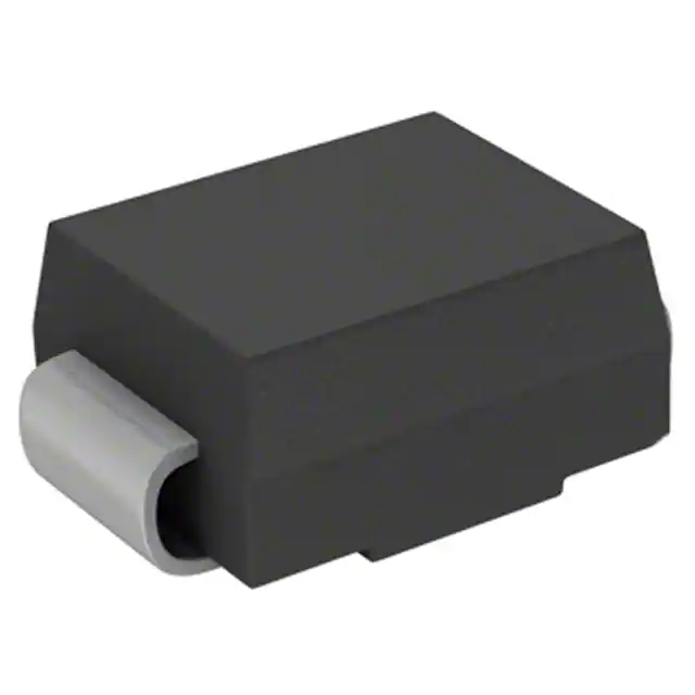
Diodes Incorporated S1MB-13-F
- Part No.:
- S1MB-13-F
- Manufacturer:
- Diodes Incorporated
- Category:
- Single Diodes
- Package:
- DO-214AA, SMB
- Datasheet:
-
 S1MB-13-F.pdf
- Description:
- DIODE GEN PURP 1KV 1A SMB
- Quantity:
- Payment:

- Shipping:

Inventory:925,352
Please send an inquiry. Send us your inquiry, and we will respond immediately.
Product details
Overview
S1MB-13-F from Diodes Incorporated is a surface-mount, glass-passivated general-purpose silicon rectifier diode in SMB package, rated for 1000 V peak repetitive reverse voltage (VRRM), 1.0 A average forward current (IO) at 100°C terminal temperature, and 30 A non-repetitive surge current (IFSM). It delivers low forward voltage drop (≤1.1 V @ 1.0 A) and fast recovery (trr ≤ 3.0 μs), making it suitable for AC/DC input rectification in offline power supplies.
For engineers reviewing the S1MB-13-F datasheet, S1MB-13-F pinout, S1MB-13-F application, or S1MB-13-F equivalent, key selection criteria include its 1000 V blocking capability, SMB thermal performance (RθJT = 30 °C/W), reverse leakage (≤100 μA @ +125°C), and RoHS-compliant matte tin termination for lead-free reflow assembly.
Technical Context
This device operates as a unidirectional, single-phase, half-wave rectifier under resistive or inductive loads at 60 Hz. Its glass-passivated junction ensures stable reverse characteristics across -65°C to +150°C operating range and supports automated pick-and-place placement due to standardized SMB footprint.
Electrical behavior is defined by a soft recovery profile (trr = 1.8–3.0 μs), low junction capacitance (CT = 10 pF @ 1 MHz, 4 V), and forward conduction with VF ≤ 1.1 V at rated DC load - enabling efficient energy conversion without snubber circuits in medium-frequency SMPS front-ends.
Key Specifications
| Parameter | Value and Actual Design Meaning |
|---|---|
| VRRM | 1000 V - Withstands peak reverse transients up to 1 kV in AC line rectification without breakdown. |
| IO @ TT=100°C | 1.0 A - Sustains continuous DC output current when mounted on PCB copper pads per JEDEC standard. |
| IFSM (8.3 ms) | 30 A - Handles inrush surges from cold-started capacitive inputs without permanent degradation. |
| VF @ IF=1.0A | ≤1.1 V - Limits conduction loss to ≤1.1 W per diode at full load, reducing thermal stress in compact layouts. |
| trr | 1.8–3.0 μs - Enables operation up to ~100 kHz switching frequencies with minimal reverse recovery loss. |
| RθJT | 30 °C/W - Junction-to-terminal thermal resistance allows direct heat transfer to PCB copper, simplifying thermal design. |
| IR @ +125°C | ≤100 μA - Low leakage preserves efficiency in high-temperature environments like enclosed power adapters. |
Pinout & Package
The S1MB-13-F uses the SMB (DO-214AA) surface-mount plastic package with cathode band marking on the top surface. Terminal polarity is unambiguous: the banded end is the cathode; the opposite end is the anode.
| Pin/Terminal | Circuit Role | Design Meaning |
|---|---|---|
| Anode | AC Input / Positive Conduction Path | Connects to AC source or transformer secondary; conducts current when forward-biased. |
| Cathode | DC Output / Negative Return Path | Delivers rectified positive voltage to filter capacitor; marked with visible band for orientation. |
Key Features
| Feature | Design Value |
|---|---|
| Glass passivated die construction | Eliminates moisture-induced corrosion and enhances long-term reliability in humid industrial environments. |
| UL 94V-0 molded plastic case | Provides flame-retardant mechanical protection and meets safety standards for Class II power supplies. |
| Lead-free, halogen-free "Green" finish | Complies with RoHS 2 and meets stringent environmental regulations for global electronics manufacturing. |
| Moisture Sensitivity Level 1 | Allows unlimited floor life before reflow, eliminating bake-out requirements in production assembly. |
| Standardized SMB footprint | Ensures compatibility with automated SMT lines and enables drop-in replacement of other DO-214AA rectifiers. |
Applications
| AC-DC Power Adapters | Industrial Motor Drives |
|---|---|
Use Scenario: 10–65 W wall-mounted AC/DC adapters for consumer electronics. IC Role / Device Role / Timing Role: Primary-side bridge rectifier converting 90–264 VAC input to pulsating DC before bulk capacitor filtering. Use Value: 1000 V VRRM margin accommodates line surges; 1.1 V VF minimizes self-heating in sealed enclosures. | Use Scenario: Control board power supply in HVAC blower modules and PLC I/O modules. IC Role / Device Role / Timing Role: Input rectifier for auxiliary 24 VDC logic supply derived from 120/240 VAC mains. Use Value: -65°C to +150°C rating ensures startup and operation across wide ambient ranges in factory settings. |
| LED Driver Front-Ends | UPS Input Stages |
Use Scenario: Constant-voltage LED drivers for commercial lighting (e.g., T8 retrofit tubes). IC Role / Device Role / Timing Role: Half-wave or full-wave rectifier feeding PFC controller ICs in universal-input designs. Use Value: 30 A IFSM withstands repeated lamp hot-plug events without degradation. | Use Scenario: Line-powered standby power circuitry in online double-conversion UPS units. IC Role / Device Role / Timing Role: Mains rectifier supplying hold-up capacitor and DC bus for inverter stage. Use Value: Low CT (10 pF) reduces EMI generation during commutation, easing EMC filter design. |
Equivalent & Alternatives
The following parts are listed as comparable options for similar general-purpose rectifier applications.
| Alternative Part | Technical Difference | Application Difference | Selection Advice |
|---|---|---|---|
| STTH1L06S | 600 V VRRM, 1.0 A IO, trr = 75 ns (ultrafast), VF = 1.15 V @ 1.0 A | Lower voltage rating; optimized for high-frequency PFC stages, not universal AC input. | Select only if system peak line voltage remains ≤ 420 V RMS and switching frequency exceeds 50 kHz. |
| ON Semi MUR1100E | 1000 V VRRM, 1.0 A IO, trr = 75 ns, VF = 1.7 V @ 1.0 A, TO-277 package | Higher VF increases conduction loss; TO-277 requires different layout and thermal pad design. | Prefer only when ultrafast recovery is mandatory and PCB space allows larger outline. |
Compared with STTH1L06S and MUR1100E, S1MB-13-F offers optimal balance of high-voltage ruggedness, moderate speed, low VF, and SMB manufacturability - ideal for cost-sensitive, thermally constrained universal-input rectification where sub-100 ns recovery is unnecessary.
Availability
S1MB-13-F is available at Aetrix Electronics and suitable for AC/DC power adapters, industrial motor drive auxiliary supplies, and LED driver front-ends requiring stable component supply, consistent parametric performance, and full RoHS/Green compliance.
Supply support for S1MB-13-F includes scheduled delivery planning, volume procurement assistance, BOM continuity management, traceable sourcing, and lifecycle availability coordination for OEM customers, industrial embedded developers, connected-device designers, and electronics production programs.
Manufacturer
Diodes Incorporated is a global manufacturer of discrete semiconductors and analog ICs, headquartered in Plano, Texas, with design, manufacturing, and sales operations across Asia, Europe, and the Americas.
The S1x-B rectifier series targets cost-effective, high-reliability AC input stage solutions for consumer, industrial, and lighting power supplies - emphasizing robust surge handling, thermal stability, and automated assembly readiness.
FAQ
What is the maximum allowable PCB copper pad area for optimal thermal performance?
The datasheet specifies thermal resistance RθJT = 30 °C/W when mounted on 5.0 mm² of 0.013 mm thick copper pad. Increasing pad area beyond this improves heat dissipation but yields diminishing returns; minimum recommended pad size is 4.3 mm × 1.8 mm (SMB footprint) with thermal vias to inner ground planes for sustained 1.0 A operation.
Can S1MB-13-F be used in full-wave bridge configurations?
Yes - S1MB-13-F is rated for single-phase, half-wave operation per datasheet test conditions, but its 1000 V VRRM and 30 A IFSM make it suitable as an individual leg in discrete full-wave bridges. Four units can form a 1000 V, 1.0 A bridge; ensure matched VF and trr across all four devices for balanced current sharing.
Is the cathode band visible under standard AOI inspection?
Yes - the cathode band is a laser-marked, opaque black stripe on the top surface of the SMB package, fully compatible with automated optical inspection systems operating at ≥10 μm resolution. Its contrast against the green-molded body ensures >99.9% detection rate in production AOI setups.
Does S1MB-13-F require derating when used with capacitive loads?
Yes - the datasheet explicitly states that for capacitive loads, average forward current must be derated by 20%. At TA = +25°C, IO must be limited to 0.8 A to maintain reliability; this reflects increased peak current stress during capacitor charging transients, which elevates junction temperature beyond resistive-load assumptions.
S1MB-13-F Specifications
- Product attributes
- Attribute value
- Manufacturer:
- Diodes Incorporated
- Series:
- -
- Package/Case:
- DO-214AA, SMB
- Packaging:
- Tape & Reel (TR)
- Product Status:
- Active
- Technology:
- Standard
- Voltage - DC Reverse (Vr) (Max):
- 1000 V
- Current - Average Rectified (Io):
- 1A
- Voltage - Forward (Vf) (Max) @ If:
- 1.1 V @ 1 A
- Speed:
- Standard Recovery >500ns, > 200mA (Io)
- Reverse Recovery Time (trr):
- 3 µs
- Current - Reverse Leakage @ Vr:
- 5 µA @ 1000 V
- Capacitance @ Vr, F:
- 10pF @ 4V, 1MHz
- Grade:
- -
- Qualification:
- -
- Mounting Type:
- Surface Mount
- Supplier Device Package:
- SMB
- Operating Temperature - Junction:
- -65°C ~ 150°C
S1MB-13-F FAQ
1.How can I place an order for S1MB-13-F through Aetrix?
Please submit a Request for Quotation (RFQ) for S1MB-13-F on Aetrix. Our sales agent will provide a competitive quotation and guide you through the order confirmation once you accept the terms.
2.Are the price and stock information for S1MB-13-F reliable?
The price and inventory of S1MB-13-F are updated periodically and may fluctuate due to market conditions. Stock and pricing data are typically refreshed every 24 hours. Quotation validity for S1MB-13-F is usually 5 days.
3.What payment methods are accepted for S1MB-13-F?
We accept Wire Transfer, PayPal, Credit Card, Western Union, MoneyGram, and Escrow for S1MB-13-F transactions.
Note: Certain payment methods may incur a processing fee.
4.How is shipping managed for S1MB-13-F?
S1MB-13-F orders can be shipped via leading logistics carriers, including DHL, UPS, FedEx, TNT, or Registered Mail.
Once your S1MB-13-F order is processed, you will receive an email with the shipment details and tracking number.
Note: Tracking information may take up to 24 hours to appear. Express delivery typically takes 3–5 business days.
5.How can I obtain technical support or documentation for S1MB-13-F?
For technical support, including S1MB-13-F datasheets, pinout diagrams, or application guidance, please contact our engineering support team. They can provide detailed documentation and assistance for your S1MB-13-F requirements.
6.How does Aetrix verify that S1MB-13-F is sourced from the original manufacturer or authorized distributors?
All S1MB-13-F products on Aetrix are procured from qualified distributors and authorized channels. Our dedicated quality assurance team conducts strict verification, including traceability checks and, if necessary, third-party testing. This ensures that S1MB-13-F meets industry standards.
7.What is the process for return or replacement of S1MB-13-F?
All S1MB-13-F units undergo pre-shipment inspection (PSI). If there is an issue with S1MB-13-F, returns or replacements are accepted under the following conditions:
1.Quantity discrepancies, incorrect items, or visible external defects (such as breakage or corrosion), acknowledged by Aetrix.
2.The issue is reported within 90 days of delivery.
3.The S1MB-13-F part is unused and in its original packaging.
Return procedure for S1MB-13-F:
1.Submit a request within 90 days.
2.Obtain a Return Material Authorization (RMA) from Aetrix.
S1MB-13-F Tags
-
1N4448X-TP
Micro Commercial Co
-
1N4148WX-TP
Micro Commercial Co

-
1N4148TR
onsemi
-
MMSD4148T1G
onsemi

-
MMBD914LT3G
onsemi
-
BAS16HT1G
onsemi
-
1N914BWT
onsemi
-
BAS21LT1G
onsemi
-
LL4148
onsemi

-
BAS16LT1G
onsemi
-
MMSD914T1G
onsemi
-
BAV21W-7-F
Diodes Incorporated
Tech Hub

Latch circuits retain one bit through feedback. This technical reference covers SR and D latches, truth tables, transparency, timing limits, latch-versus-flip-flop behavior, applications and common log…

An engineering guide to LED driver operation, constant-current and constant-voltage outputs, linear and switching topologies, dimming, IC selection, calculations, replacement compatibility, and fault c…

Operational amplifier guide covering op amp basics, feedback, ideal vs real op amps, common configurations, buffer circuits, offset, bias current, gain-bandwidth, slew rate, rail-to-rail limits and sel…

Jumper cables guide covering safe connection order, red and black clamp placement, final ground connection, cable gauge, length, clamp quality, copper vs CCA cables, jump starter comparison and battery…

LDO regulator guide covering low dropout voltage, power dissipation, thermal design, PSRR, output noise, capacitor stability, adjustable LDO circuits, LDO vs buck converter and datasheet selection chec…

Conditional Access Module guide covering CAM meaning, CI/CI+ interface, smart card authorization, DVB security workflow, TV and set-top box compatibility, internal electronics, ESD protection, connecto…

Guide to electronic component obsolescence covering EOL risk, PCN/PDN notices, last-time buy planning, replacement options, form-fit-function validation, counterfeit risk and BOM lifecycle management.

18650 battery guide covering lithium-ion cell basics, 3.6V/3.7V voltage, 4.2V charging, mAh and Wh capacity, protected cells, chargers, BMS, series-parallel packs, holders, welding and sourcing checks.…

Hall effect sensor guide covering working principle, linear and digital sensors, Arduino circuits, current sensing, speed detection, automotive applications, A3144 examples, signal filtering and datash…

Product Change Notification guide for electronic components, covering PCN meaning, PCN vs PDN/EOL, common change types, risk levels, form-fit-function review, engineering validation, BOM control, LTB/L…


