
 My Inquiry
 My Account


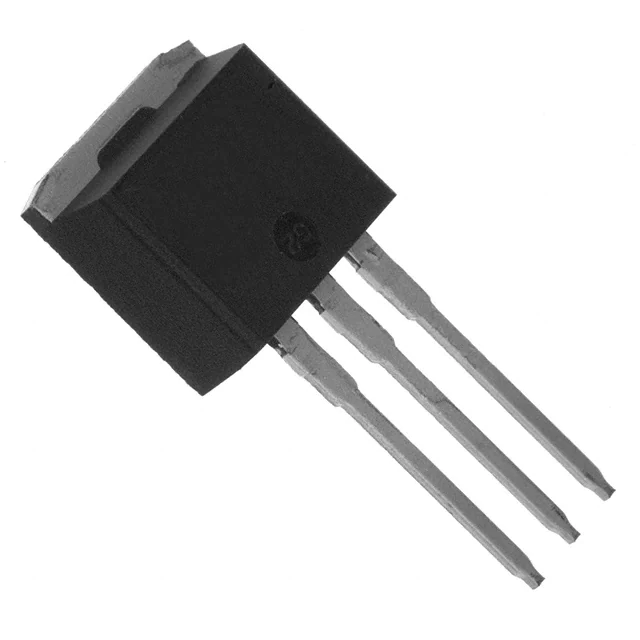
Diodes Incorporated SBR20100CTE
- Part No.:
- SBR20100CTE
- Manufacturer:
- Diodes Incorporated
- Category:
- Diode Arrays
- Package:
- TO-262-3 Long Leads, I2PAK, TO-262AA
- Datasheet:
-
 SBR20100CTE.pdf
- Description:
- DIODE ARRAY SBR 100V 10A TO-262
- Quantity:
- Payment:

- Shipping:

Inventory:50
Please send an inquiry. Send us your inquiry, and we will respond immediately.
Product details
Overview
SBR20100CTE from Diodes Incorporated is a 20A dual common-cathode super barrier rectifier in TO-262 package, rated for 100V peak reverse voltage and featuring 0.67V typical forward voltage at 10A/25°C. It delivers soft fast switching, high-temperature stability up to +175°C junction, and RoHS-compliant matte tin terminals - deployed in high-efficiency AC/DC front-end rectification for industrial power supplies.
For engineers reviewing the SBR20100CTE datasheet, SBR20100CTE pinout, SBR20100CTE application, or SBR20100CTE equivalent, key selection criteria include per-leg forward voltage (0.67–0.82V), thermal resistance (2°C/W), leakage current (≤20µA @125°C), surge rating (180A), and TO-262 mechanical compatibility with heatsink mounting.
Technical Context
This dual-anode, single-common-cathode rectifier integrates two independent 10A legs sharing one cathode terminal, enabling synchronous half-wave or center-tapped full-wave configurations. Its patented Super Barrier Rectifier (SBR®) structure replaces traditional PN junctions with low-barrier metal-semiconductor interfaces, reducing forward conduction loss while maintaining soft recovery characteristics.
Thermal design is enabled by direct die-to-case conduction via copper leadframe and low RθJC of 2°C/W per leg. Operation across –65°C to +175°C ambient is supported by stable VF and IR performance, with leakage rising only to 20µA at 125°C under 100V reverse bias.
Key Specifications
| Parameter | Value and Actual Design Meaning |
|---|---|
| VRRM | 100 V - Maximum repetitive reverse voltage per leg; defines safe blocking capability in 100V-rated DC bus or PFC stage applications. |
| IO (per leg) | 10 A - Continuous average forward current per anode leg; supports 20A total device output in dual-anode configuration. |
| VF @10A/25°C | 0.67 V - Low conduction loss reduces I²R heating and improves system efficiency in high-current rectification paths. |
| RθJC | 2 °C/W - Enables direct heatsink mounting without thermal interface material; simplifies thermal management in compact power modules. |
| IFSM | 180 A - Withstands 8.3ms half-sine surge; protects against line transients and inrush currents in offline SMPS inputs. |
| IR @100V/125°C | 20 µA - Ultra-low high-temp leakage preserves efficiency and reliability in thermally stressed environments like enclosed industrial enclosures. |
Pinout & Package
Package: TO-262 (3-lead, straight lead, isolated tab). Case material is UL 94V-0 molded plastic; terminals are matte tin over copper leadframe, solderable per MIL-STD-202 Method 208.
| Pin/Terminal | Circuit Role | Design Meaning |
|---|---|---|
| 1 (Anode A) | First anode connection | Accepts AC input or transformer secondary winding; electrically isolated from Pin 3 (cathode) and Pin 2 (Anode B). |
| 2 (Anode B) | Second anode connection | Enables dual-input or center-tapped full-wave rectification; shares common cathode with Pin 1. |
| 3 (Cathode) | Common cathode node | Single output node for both legs; must be connected to positive rail or smoothing capacitor; tab is electrically tied to this pin. |
Key Features
| Feature | Design Value |
|---|---|
| Super Barrier Rectifier (SBR®) technology | Replaces conventional PN junction with low-barrier Schottky-like structure, achieving 0.67V VF without hard reverse recovery spikes. |
| Soft, fast switching | Minimizes EMI generation during turn-off; eliminates need for snubbers in 50–100kHz switch-mode power supplies. |
| High-temperature stability | Leakage remains ≤20µA and VF increases only marginally (to 0.71V) at 125°C, ensuring consistent performance in sealed enclosures. |
| TO-262 thermal interface | Isolated metal tab directly bonded to cathode (Pin 3), enabling efficient heat transfer to external heatsink without insulating pads. |
Applications
| Industrial AC/DC Power Supplies | Server PSU Front-End Rectification |
|---|---|
Use Scenario: 3kW telecom rectifier module converting 230VAC input to 48VDC bus using center-tapped transformer and dual-anode rectification. IC Role / Device Role / Timing Role: Dual-anode super barrier rectifier providing low-loss, high-reliability output rectification with shared cathode return path. Use Value: 0.67V forward drop at 10A reduces conduction loss by ~35% vs. standard FRD, lowering thermal stress on heatsink and improving system efficiency to >92%. | Use Scenario: High-density 1U server power supply requiring compact, thermally robust 20A output rectification in constrained airflow environment. IC Role / Device Role / Timing Role: Dual-leg rectifier operating in parallel half-wave mode to deliver 20A continuous output while minimizing footprint and thermal resistance. Use Value: 2°C/W RθJC enables direct heatsink mounting without thermal paste, reducing assembly steps and long-term interface degradation risk. |
| LED Driver Secondary Side | Industrial Motor Drive DC Link |
Use Scenario: Constant-current LED driver with 100V-rated secondary-side rectification feeding buck converter, operating continuously at 85°C ambient. IC Role / Device Role / Timing Role: Output rectifier handling 10A average current per leg with minimal voltage drop to preserve regulation headroom. Use Value: Stable 0.71V VF at 125°C ensures predictable output ripple and avoids thermal runaway during sustained high-temp operation. | Use Scenario: 3-phase inverter DC link rectification in HVAC variable-frequency drive, where surge immunity and leakage control are critical. IC Role / Device Role / Timing Role: Input-stage rectifier absorbing regenerative energy and clamping bus voltage during motor braking events. Use Value: 180A non-repetitive surge rating withstands transient overcurrents from motor back-EMF, while 20µA IR at 125°C prevents bus leakage-induced instability. |
Equivalent & Alternatives
The following parts are listed as comparable options for similar high-current, low-VF rectifier applications.
| Alternative Part | Technical Difference | Application Difference | Selection Advice |
|---|---|---|---|
| STPS20H100CG | Same TO-262 package, 20A/100V Schottky; VF = 0.72V @10A/25°C; higher IR (100µA @125°C). | Lacks soft recovery; may require snubber in high-dv/dt environments. | Prefer when lowest possible VF is primary goal and EMI filtering is already present. |
| MBR20100CT | Standard dual Schottky in TO-220AB; VF = 0.85V @10A/25°C; RθJC = 3.5°C/W; no soft switching. | Higher conduction loss and thermal resistance; unsuitable for >85°C ambient without oversized heatsink. | Select only if TO-220AB footprint is mandatory and thermal budget allows 15–20% higher loss. |
Compared with STPS20H100CG and MBR20100CT, the SBR20100CTE uniquely balances ultra-low VF (0.67V), soft recovery, and low leakage (20µA) - making it optimal for thermally constrained, EMI-sensitive industrial power stages where reliability across temperature extremes is required.
Availability
SBR20100CTE is available at Aetrix Electronics and suitable for industrial AC/DC power supplies, server PSU front-end rectification, and LED driver secondary-side applications requiring stable component supply, long-lifecycle support, and RoHS-compliant manufacturing.
Supply support for SBR20100CTE includes scheduled delivery planning, volume procurement assistance, BOM continuity management, traceable sourcing, and lifecycle availability coordination for OEM customers, industrial embedded developers, connected-device designers, and electronics production programs.
Manufacturer
Diodes Incorporated is a global manufacturer of discrete semiconductors and analog ICs, specializing in high-efficiency power management, signal integrity, and protection solutions for industrial, computing, and consumer markets.
The SBR® Super Barrier Rectifier product line was developed to replace conventional Schottky and fast recovery diodes in high-current, high-temperature rectification applications - delivering lower VF, softer switching, and superior thermal stability without compromising ruggedness.
FAQ
What is the maximum junction temperature rating for SBR20100CTE?
The SBR20100CTE has a specified operating junction temperature range of –65°C to +175°C. This rating is validated per JEDEC test conditions and confirmed in the DS31971 datasheet's Thermal Characteristics table. The device maintains electrical performance within spec across this full range, with leakage current and forward voltage characterized at 25°C, 85°C, and 125°C.
Is the TO-262 package of SBR20100CTE electrically isolated?
No - the metal tab of the TO-262 package is electrically connected to Pin 3 (common cathode), not isolated. This is explicitly shown in the "Package Pin Out Configuration" diagram and confirmed by the mechanical drawing where the tab is labeled as cathode. Designers must ensure the heatsink or mounting surface is either grounded or otherwise referenced to the cathode potential.
How does the SBR20100CTE differ from standard Schottky rectifiers in switching behavior?
Unlike standard Schottky diodes, the SBR20100CTE uses a patented super barrier structure that provides soft, fast reverse recovery - reducing high-frequency ringing and EMI. Standard Schottkys exhibit abrupt turn-off with minimal stored charge but no controlled recovery; the SBR achieves similar low VF while adding controlled minority-carrier recombination for smoother dv/dt transitions.
Can SBR20100CTE be used in place of a single 20A standard diode?
No - the SBR20100CTE is a dual-anode, common-cathode device (two 10A legs), not a single 20A path. It cannot substitute for a monolithic 20A diode unless the circuit topology uses dual inputs (e.g., center-tapped transformer or interleaved phases). Using only one anode leg de-rates the device to 10A and leaves the second anode floating, risking voltage imbalance or failure.
SBR20100CTE Specifications
- Product attributes
- Attribute value
- Manufacturer:
- Diodes Incorporated
- Series:
- SBR®
- Package/Case:
- TO-262-3 Long Leads, I2PAK, TO-262AA
- Packaging:
- Tube
- Product Status:
- Active
- Diode Configuration:
- 1 Pair Common Cathode
- Technology:
- Super Barrier
- Voltage - DC Reverse (Vr) (Max):
- 100 V
- Current - Average Rectified (Io) (per Diode):
- 10A
- Voltage - Forward (Vf) (Max) @ If:
- 820 mV @ 10 A
- Speed:
- Standard Recovery >500ns, > 200mA (Io)
- Reverse Recovery Time (trr):
- -
- Current - Reverse Leakage @ Vr:
- 100 µA @ 100 V
- Operating Temperature - Junction:
- -65°C ~ 150°C
- Grade:
- -
- Qualification:
- -
- Mounting Type:
- Through Hole
- Supplier Device Package:
- TO-262
SBR20100CTE FAQ
1.How can I place an order for SBR20100CTE through Aetrix?
Please submit a Request for Quotation (RFQ) for SBR20100CTE on Aetrix. Our sales agent will provide a competitive quotation and guide you through the order confirmation once you accept the terms.
2.Are the price and stock information for SBR20100CTE reliable?
The price and inventory of SBR20100CTE are updated periodically and may fluctuate due to market conditions. Stock and pricing data are typically refreshed every 24 hours. Quotation validity for SBR20100CTE is usually 5 days.
3.What payment methods are accepted for SBR20100CTE?
We accept Wire Transfer, PayPal, Credit Card, Western Union, MoneyGram, and Escrow for SBR20100CTE transactions.
Note: Certain payment methods may incur a processing fee.
4.How is shipping managed for SBR20100CTE?
SBR20100CTE orders can be shipped via leading logistics carriers, including DHL, UPS, FedEx, TNT, or Registered Mail.
Once your SBR20100CTE order is processed, you will receive an email with the shipment details and tracking number.
Note: Tracking information may take up to 24 hours to appear. Express delivery typically takes 3–5 business days.
5.How can I obtain technical support or documentation for SBR20100CTE?
For technical support, including SBR20100CTE datasheets, pinout diagrams, or application guidance, please contact our engineering support team. They can provide detailed documentation and assistance for your SBR20100CTE requirements.
6.How does Aetrix verify that SBR20100CTE is sourced from the original manufacturer or authorized distributors?
All SBR20100CTE products on Aetrix are procured from qualified distributors and authorized channels. Our dedicated quality assurance team conducts strict verification, including traceability checks and, if necessary, third-party testing. This ensures that SBR20100CTE meets industry standards.
7.What is the process for return or replacement of SBR20100CTE?
All SBR20100CTE units undergo pre-shipment inspection (PSI). If there is an issue with SBR20100CTE, returns or replacements are accepted under the following conditions:
1.Quantity discrepancies, incorrect items, or visible external defects (such as breakage or corrosion), acknowledged by Aetrix.
2.The issue is reported within 90 days of delivery.
3.The SBR20100CTE part is unused and in its original packaging.
Return procedure for SBR20100CTE:
1.Submit a request within 90 days.
2.Obtain a Return Material Authorization (RMA) from Aetrix.
SBR20100CTE Tags
-
BAV99-7-F
Diodes Incorporated
-
BAT54C-7-F
Diodes Incorporated
-
BAV99,215
Nexperia USA Inc.

-
BAT54SLT1G
onsemi

-
BAV70LT1G
onsemi
-
BAT54CLT1G
onsemi
-
BAT54S-7-F
Diodes Incorporated
-
BAV99LT1G
onsemi
-
BAT54S,215
Nexperia USA Inc.
-
BAS40-04LT1G
onsemi
-
MMBD1503-TP
Micro Commercial Co
-
BAV99WT1G
onsemi
Tech Hub

An engineering guide to LED driver operation, constant-current and constant-voltage outputs, linear and switching topologies, dimming, IC selection, calculations, replacement compatibility, and fault c…

Operational amplifier guide covering op amp basics, feedback, ideal vs real op amps, common configurations, buffer circuits, offset, bias current, gain-bandwidth, slew rate, rail-to-rail limits and sel…

Jumper cables guide covering safe connection order, red and black clamp placement, final ground connection, cable gauge, length, clamp quality, copper vs CCA cables, jump starter comparison and battery…

LDO regulator guide covering low dropout voltage, power dissipation, thermal design, PSRR, output noise, capacitor stability, adjustable LDO circuits, LDO vs buck converter and datasheet selection chec…

Conditional Access Module guide covering CAM meaning, CI/CI+ interface, smart card authorization, DVB security workflow, TV and set-top box compatibility, internal electronics, ESD protection, connecto…

Guide to electronic component obsolescence covering EOL risk, PCN/PDN notices, last-time buy planning, replacement options, form-fit-function validation, counterfeit risk and BOM lifecycle management.

18650 battery guide covering lithium-ion cell basics, 3.6V/3.7V voltage, 4.2V charging, mAh and Wh capacity, protected cells, chargers, BMS, series-parallel packs, holders, welding and sourcing checks.…

Hall effect sensor guide covering working principle, linear and digital sensors, Arduino circuits, current sensing, speed detection, automotive applications, A3144 examples, signal filtering and datash…

Product Change Notification guide for electronic components, covering PCN meaning, PCN vs PDN/EOL, common change types, risk levels, form-fit-function review, engineering validation, BOM control, LTB/L…

A practical guide to blend door actuators, covering HVAC function, symptoms, location, AC and heater issues, reset and calibration, replacement cost, electrical diagnosis, compatibility checks, and rep…


