
 My Inquiry
 My Account


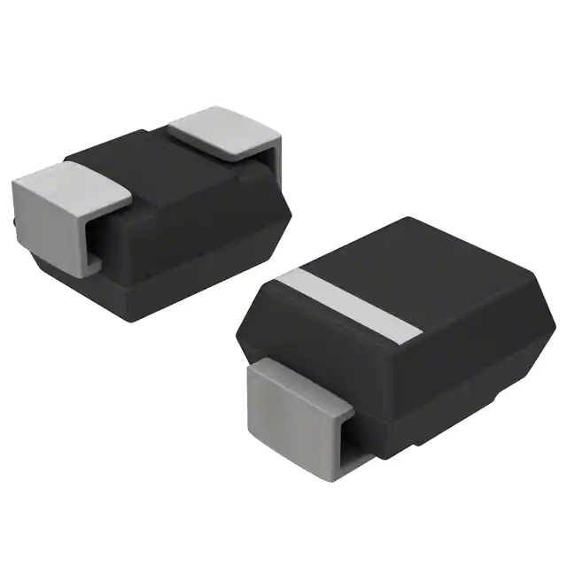
STMicroelectronics SMP50-130
- Part No.:
- SMP50-130
- Manufacturer:
- STMicroelectronics
- Category:
- Thyristors
- Package:
- DO-214AC, SMA
- Datasheet:
-
 SMP50-130.pdf
- Description:
- THYRISTOR 130V 150A DO-214AC
- Quantity:
- Payment:

- Shipping:

Inventory:21,830
Please send an inquiry. Send us your inquiry, and we will respond immediately.
Product details
Overview
SMP50-130 from STMicroelectronics is a bidirectional Trisil™ thyristor surge protection device designed for primary overvoltage clamping on telecom line interfaces. It features a 130 V standoff voltage (VRM), 173 V dynamic breakover voltage (VBO), 14 mA minimum holding current (IH), 50 A repetitive peak pulse current (10/1000 µs), and 30 pF capacitance at 50 V - enabling robust lightning and transient suppression in xDSL and T1/E1 line cards without signal integrity degradation.
For engineers reviewing the SMP50-130 datasheet, SMP50-130 pinout, SMP50-130 application, or SMP50-130 equivalent, this device is selected for fail-safe short-circuit crowbar behavior, UL497B and GR-1089 compliance, low leakage (<2 µA), and JEDEC DO-214AC (SMA) surface-mount packaging - critical for telecom surge protection layout and reliability validation.
Technical Context
The SMP50-130 operates as a voltage-triggered bidirectional thyristor, entering low-impedance conduction when transient voltage exceeds its 173 V dynamic breakover threshold. Its fail-safe short-circuit mode ensures continued protection even after end-of-life stress events.
It delivers 50 A peak pulse handling per 10/1000 µs waveform with thermal resistance of 120 °C/W (junction-to-ambient, SMA package) and maintains stable VBO across junction temperature (±10% variation from –40°C to 125°C), supporting operation in uncontrolled telecom cabinet environments.
Key Specifications
| Parameter | Value and Actual Design Meaning |
|---|---|
| Standoff Voltage (VRM) | 130 V - maximum continuous reverse voltage before triggering; sets operating margin above 48 V DC telecom line bias. |
| Dynamic Breakover Voltage (VBO) | 173 V - actual turn-on threshold under fast transients (100 V/µs); defines clamping level during lightning surges. |
| Holding Current (IH) | 14 mA min - minimum current required to sustain conduction; ensures reliable latching during sustained overvoltage events. |
| Peak Pulse Current (IPP) | 50 A (10/1000 µs) - surge-handling capability aligned with GR-1089 Core Level 1 and ITU-T K20 standards. |
| Capacitance (C) | 30 pF @ 50 V - low parasitic capacitance preserves high-frequency signal integrity on DSL and ISDN lines. |
| Leakage Current (IRM) | 2 µA max @ 130 V - negligible standby power loss and minimal impact on line impedance matching. |
| Package | SMA (DO-214AC) - JEDEC-standardized surface-mount footprint compatible with automated assembly and IPC-7351B land patterns. |
Pinout & Package
SMP50-130 is housed in an SMA (DO-214AC) plastic package with cathode-anode symmetry optimized for bidirectional line protection. The package meets UL94 V0 flammability rating and supports 260 °C lead-free soldering (10 s).
| Pin/Terminal | Circuit Role | Design Meaning |
|---|---|---|
| Anode (A) | Triggered conduction terminal (bidirectional) | Acts as either anode or cathode depending on polarity of transient; enables symmetrical clamping on AC-coupled telecom lines. |
| Cathode (K) | Triggered conduction terminal (bidirectional) | Paired with Anode to form low-impedance crowbar path; no polarity marking required due to symmetric construction. |
Key Features
| Feature | Design Value |
|---|---|
| Fail-safe short-circuit mode | Guarantees permanent low-impedance state upon end-of-life, preventing open-circuit failure and maintaining equipment safety. |
| UL497B certification (E136224) | Validated for primary-side telecom surge protection in FCC Part 68-compliant equipment including central office and CPE designs. |
| Low 30 pF capacitance @ 50 V | Minimizes insertion loss and phase distortion on broadband xDSL signals up to 30 MHz, preserving data throughput. |
| No aging degradation | Stable electrical parameters over 10+ years of field operation; eliminates recalibration or preventive replacement cycles. |
| JEDEC DO-214AC (SMA) footprint | Enables drop-in placement on existing telecom PCBs and compatibility with standard reflow profiles for high-volume manufacturing. |
Applications
| DSL Line Card Protection | T1/E1 Interface Protection |
|---|---|
Use Scenario: Protects ADSL/VDSL line interface circuits from lightning-induced surges on twisted-pair copper loops. IC Role / Device Role / Timing Role: Primary crowbar protector placed upstream of line driver/receiver ICs to clamp transients before they reach sensitive analog front-end components. Use Value: Enables compliance with ITU-T K20 (6 kV/1500 A) and GR-1089 Core Level 1 while maintaining <0.5 dB insertion loss at 2.2 MHz. | Use Scenario: Shields T1/E1 framing and timing recovery circuitry in channel banks and multiplexers from AC power cross-talk and induced surges. IC Role / Device Role / Timing Role: Bidirectional voltage clamp on balanced differential pairs carrying 1.544/2.048 Mbps data with precise jitter tolerance. Use Value: Limits clamping voltage to ≤173 V with <30 pF loading, preserving eye diagram integrity and reducing bit error rate under surge stress. |
| ISDN Terminal Protection | Central Office Line Card Protection |
Use Scenario: Integrated into BRI NT1 devices and ISDN terminal adapters to meet UL1459 and FCC Part 68 surge requirements. IC Role / Device Role / Timing Role: Fail-safe overvoltage limiter on U-interface (2B+D) lines, directly coupled to transformer secondary windings. Use Value: Provides guaranteed short-circuit failure mode and UL94 V0 epoxy housing - satisfying safety agency requirements for Class 2 circuits. | Use Scenario: Deployed on carrier-grade line cards handling hundreds of subscriber lines in digital switching systems. IC Role / Device Role / Timing Role: First-stage protector in multi-level cascade (with GDT and TVS), absorbing >80% of 5 kV/500 A GR-1089 Level 2 surges. Use Value: Delivers 50 A peak pulse rating with 120 °C/W thermal resistance, enabling natural convection cooling without heatsinks in dense card layouts. |
Equivalent & Alternatives
The following parts are listed as comparable options for similar bidirectional telecom surge protection applications.
| Alternative Part | Technical Difference | Application Difference | Selection Advice |
|---|---|---|---|
| Littelfuse SP1003-010 | Unidirectional; 100 V standoff; 150 A (8/20 µs) rating; higher capacitance (65 pF) | Requires external series resistor for bidirectional use; better suited for power-line side protection | Select only if unidirectional clamping and higher surge rating outweigh signal integrity trade-offs. |
| Vishay V130LA20AP | MOV-based; 130 V AC RMS rating; no defined holding current; degrades with repeated surges | Lacks fail-safe short-circuit mode; requires periodic replacement per IEC61643-21 | Use only in cost-sensitive, non-safety-critical applications where lifetime reliability is secondary. |
Compared with SP1003-010 and V130LA20AP, SMP50-130 uniquely combines bidirectional symmetry, deterministic fail-safe behavior, low 30 pF capacitance, and zero aging - making it the preferred choice for long-lifetime, signal-integrity-critical telecom line interfaces.
Availability
SMP50-130 is available at Aetrix Electronics and suitable for DSL line cards, T1/E1 interface modules, ISDN terminals, and central office line cards requiring stable component supply, long-term lifecycle support, and certified surge protection performance.
Supply support for SMP50-130 includes scheduled delivery planning, volume procurement assistance, BOM continuity management, traceable sourcing, and lifecycle availability coordination for OEM customers, industrial embedded developers, connected-device designers, and electronics production programs.
Manufacturer
STMicroelectronics is a global semiconductor leader headquartered in Geneva, Switzerland, with design and manufacturing operations across Europe, Asia, and the Americas.
The Trisil™ product line was developed specifically for fail-safe, high-reliability overvoltage protection in telecom infrastructure - emphasizing UL497B certification, GR-1089 compliance, and long-term parameter stability under repeated surge stress.
FAQ
What is the fail-safe behavior of SMP50-130 during end-of-life?
The SMP50-130 enters a permanent short-circuit state when degraded by repeated surges, ensuring downstream circuitry remains protected instead of exposed to unclamped transients. This behavior is intrinsic to its thyristor structure and verified per UL497B test protocol E136224, eliminating risk of open-circuit failure in safety-critical telecom deployments.
Can SMP50-130 be used in AC mains protection applications?
No - SMP50-130 is rated for telecom signal-line protection only, with a 130 V standoff voltage and thermal limits unsuitable for 120/230 VAC mains. Its 120 °C/W junction-to-ambient resistance and lack of VDE/IEC61000-4-5 Level 4 certification preclude use in power-line surge protection; dedicated MOVs or GDTs are required instead.
How does SMP50-130 differ from standard TVS diodes in telecom protection?
Unlike avalanche TVS diodes, SMP50-130 uses thyristor-based crowbar action with defined holding current (14 mA min) and fail-safe shorting. It offers lower capacitance (30 pF vs. typical 60–100 pF), no wear-out mechanism, and superior GR-1089 Level 1 surge handling (50 A vs. 30–40 A for same package), making it ideal for high-density, long-lifecycle line cards.
Is SMP50-130 compatible with lead-free reflow processes?
Yes - SMP50-130's SMA package is qualified for lead-free soldering at 260 °C for 10 seconds, meeting JEDEC J-STD-020 moisture sensitivity level 1 and RoHS Directive 2011/65/EU. Its UL94 V0 epoxy housing remains dimensionally stable and electrically intact through standard Pb-free reflow profiles including peak temperatures up to 260 °C.
SMP50-130 Specifications
- Product attributes
- Attribute value
- Manufacturer:
- STMicroelectronics
- Package/Case:
- DO-214AC, SMA
- Series:
- SMP, TRISIL™
- Packaging:
- Tape & Reel (TR)
- Product Status:
- Active
- Voltage - Breakover:
- 173V
- Voltage - Off State:
- 130V
- Voltage - On State:
- -
- Current - Peak Pulse (8/20µs):
- 150 A
- Current - Peak Pulse (10/1000µs):
- 50 A
- Current - Hold (Ih):
- 150 mA
- Number of Elements:
- 1
- Capacitance:
- 30pF
- Grade:
- -
- Qualification:
- -
- Mounting Type:
- Surface Mount
- Supplier Device Package:
- DO-214AC (SMA)
SMP50-130 FAQ
1.How can I place an order for SMP50-130 through Aetrix?
Please submit a Request for Quotation (RFQ) for SMP50-130 on Aetrix. Our sales agent will provide a competitive quotation and guide you through the order confirmation once you accept the terms.
2.Are the price and stock information for SMP50-130 reliable?
The price and inventory of SMP50-130 are updated periodically and may fluctuate due to market conditions. Stock and pricing data are typically refreshed every 24 hours. Quotation validity for SMP50-130 is usually 5 days.
3.What payment methods are accepted for SMP50-130?
We accept Wire Transfer, PayPal, Credit Card, Western Union, MoneyGram, and Escrow for SMP50-130 transactions.
Note: Certain payment methods may incur a processing fee.
4.How is shipping managed for SMP50-130?
SMP50-130 orders can be shipped via leading logistics carriers, including DHL, UPS, FedEx, TNT, or Registered Mail.
Once your SMP50-130 order is processed, you will receive an email with the shipment details and tracking number.
Note: Tracking information may take up to 24 hours to appear. Express delivery typically takes 3–5 business days.
5.How can I obtain technical support or documentation for SMP50-130?
For technical support, including SMP50-130 datasheets, pinout diagrams, or application guidance, please contact our engineering support team. They can provide detailed documentation and assistance for your SMP50-130 requirements.
6.How does Aetrix verify that SMP50-130 is sourced from the original manufacturer or authorized distributors?
All SMP50-130 products on Aetrix are procured from qualified distributors and authorized channels. Our dedicated quality assurance team conducts strict verification, including traceability checks and, if necessary, third-party testing. This ensures that SMP50-130 meets industry standards.
7.What is the process for return or replacement of SMP50-130?
All SMP50-130 units undergo pre-shipment inspection (PSI). If there is an issue with SMP50-130, returns or replacements are accepted under the following conditions:
1.Quantity discrepancies, incorrect items, or visible external defects (such as breakage or corrosion), acknowledged by Aetrix.
2.The issue is reported within 90 days of delivery.
3.The SMP50-130 part is unused and in its original packaging.
Return procedure for SMP50-130:
1.Submit a request within 90 days.
2.Obtain a Return Material Authorization (RMA) from Aetrix.
SMP50-130 Tags
-
TISP4015L1AJR-S
Bourns Inc.
-
TISP4015L1BJR-S
Bourns Inc.
-
SMP100LC-270
STMicroelectronics
-
TISP4240M3BJR-S
Bourns Inc.
-
SMP100LC-35
STMicroelectronics
-
SMP100LC-65
STMicroelectronics
-
SMP100LC-8
STMicroelectronics
-
TISP4P035L1NR-S
Bourns Inc.
-
TISP4350H3BJR-S
Bourns Inc.
-
TISP4011H1BJR-S
Bourns Inc.
-
SMP100LC-400
STMicroelectronics
-
P0300SALRP
Littelfuse Inc.
Tech Hub

Jumper cables guide covering safe connection order, red and black clamp placement, final ground connection, cable gauge, length, clamp quality, copper vs CCA cables, jump starter comparison and battery…

LDO regulator guide covering low dropout voltage, power dissipation, thermal design, PSRR, output noise, capacitor stability, adjustable LDO circuits, LDO vs buck converter and datasheet selection chec…

Conditional Access Module guide covering CAM meaning, CI/CI+ interface, smart card authorization, DVB security workflow, TV and set-top box compatibility, internal electronics, ESD protection, connecto…

Guide to electronic component obsolescence covering EOL risk, PCN/PDN notices, last-time buy planning, replacement options, form-fit-function validation, counterfeit risk and BOM lifecycle management.

18650 battery guide covering lithium-ion cell basics, 3.6V/3.7V voltage, 4.2V charging, mAh and Wh capacity, protected cells, chargers, BMS, series-parallel packs, holders, welding and sourcing checks.…

Hall effect sensor guide covering working principle, linear and digital sensors, Arduino circuits, current sensing, speed detection, automotive applications, A3144 examples, signal filtering and datash…

Product Change Notification guide for electronic components, covering PCN meaning, PCN vs PDN/EOL, common change types, risk levels, form-fit-function review, engineering validation, BOM control, LTB/L…

A practical guide to blend door actuators, covering HVAC function, symptoms, location, AC and heater issues, reset and calibration, replacement cost, electrical diagnosis, compatibility checks, and rep…

Engineering guide to Raspberry Pi alternatives, covering chip-level differences, Orange Pi, ROCK, Jetson, Banana Pi, NanoPi, Compute Module, Pico, GPIO, camera, HAT compatibility, and replacement risks…

Engineering guide to dynamic load response testing for high-current buck converters, covering load step setup, slew rate, Vcore undershoot, overshoot, recovery time, probe location, output capacitors a…


