
 My Inquiry
 My Account


STMicroelectronics STCC02-ED5
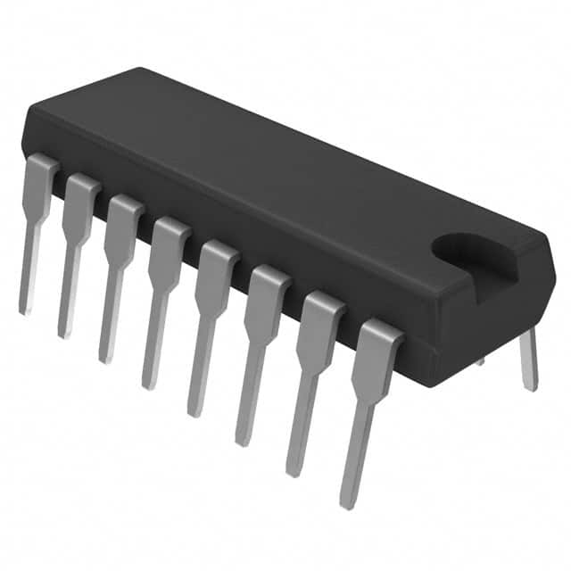
- Part No.:
- STCC02-ED5
- Manufacturer:
- STMicroelectronics
- Category:
- Power Management - Specialized
- Package:
- 16-DIP (0.300", 7.62mm)
- Datasheet:
-
 STCC02-ED5.pdf
- Description:
- IC CTRL CIRCUIT MCU APPL 16-DIP
- Quantity:
- Payment:

- Shipping:

Inventory:4,772
Please send an inquiry. Send us your inquiry, and we will respond immediately.
Product details
Overview
STCC02-ED5 from STMicroelectronics is a dedicated home appliance control circuit for microwave oven MCU-based systems, integrating 5 V ±10% voltage regulation, MCU reset with 6 ms programmable delay and 45 µs noise filtering, 30 µs filtered zero-voltage synchronization (ZVS), door-closed detection, dual 100 mA relay drivers (fan/magnetron), and a 17 mA buzzer driver - all in a DIP-16 package operating from 7–27 V input.
For engineers reviewing the STCC02-ED5 datasheet, STCC02-ED5 pinout, STCC02-ED5 application, or STCC02-ED5 equivalent, this device serves as a system-level analog/power interface IC that replaces discrete reset, ZVS, relay drive, and safety monitoring functions in microwave control modules - enabling compact, ESD-robust, IEC61000-4-compliant designs with reduced board area and solder joint count.
Technical Context
The STCC02-ED5 implements a thermally optimized 5 V linear regulator (±10% accuracy over −10 to +80 °C, 5–20 mA load) with internal overcurrent limiting and 1.25 V reference. Its reset circuit uses hysteresis (VH = 4.25 V, VL = 3.75 V) and external capacitor-programmable delay (TUP = 6 ms @ CUP = 47 nF).
The ZVS circuit generates AC-line-synchronized timing via SYN pin with 10–70 µs transition filtering and 0.4–0.9 V threshold; output falls on zero-crossing for NMI triggering. Door closed detection (CDD) provides redundant safety logic by conditioning DS input through 50 kΩ pull-down and spike suppression, feeding both MCU and magnetron enable logic (DS·IN2·FAN1̅).
Key Specifications
| Parameter | Value and Actual Design Meaning |
|---|---|
| Supply Input Range | 7–27 V DC - supports wide-range unregulated transformer secondary outputs without external pre-regulation. |
| 5 V Regulator Output | 4.5–5.5 V @ 5–20 mA - maintains ADC accuracy and timer stability across temperature and load variation. |
| Reset Threshold Hysteresis | 0.3–0.5 V - prevents oscillation during brown-out recovery and ensures clean MCU initialization. |
| ZVS Filtering Time | 10–70 µs - suppresses line transients while preserving <50 µs timing jitter for precise cooking cycle control. |
| Fan/Magnetron Driver Current | 100 mA DC sink per channel - drives standard 12 V/1.2 W relay coils with integrated demagnetizing diodes. |
| Buzzer Drive Capability | 17 mA @ up to 5 kHz PWM - delivers audible feedback without external amplification or level-shifting. |
| ESD Robustness | ±2 kV HBM - meets industrial-grade immunity requirements per MIL-STD-883 method 3015. |
| Ambient Operating Range | −10 to +80 °C - validated for enclosed microwave cavity environments with natural convection cooling. |
Pinout & Package
DIP-16 plastic dual-in-line package (20.0 × 8.5 mm, 3.3 mm height, 1.27 mm lead pitch), compliant with JEDEC MS-001, with tin-lead leads and 1 g unit weight.
| Pin/Terminal | Circuit Role | Design Meaning |
|---|---|---|
| VIN | Main supply input | Accepts 7–27 V unregulated DC; feeds internal regulator and driver stages. |
| DLC | Reset delay capacitor connection | External 47 nF sets 6 ms power-up reset assertion delay; enables controlled MCU boot sequence. |
| SYN | ZVS AC line sensing input | Receives scaled mains waveform via RZV; triggers synchronized NMI on falling edge after 30 µs filter. |
| DS | Door switch input | High-impedance safety signal (0.5 V open / 7–27 V closed); referenced to COM, pulls down via 50 kΩ. |
| MAG2 | Magnetron relay driver output | Open-collector NPN sink (100 mA max); demagnetization path tied to DS for fail-safe shutdown when door opens. |
| /RST | MCU reset output | Active-low open-drain signal; asserts low when VDD < 3.75 V, deasserts after 6 ms delay when VDD > 4.25 V. |
| CDD | Door closed detection output | 5 V logic-level copy of DS state; used by MCU for redundant interlock verification. |
| IN1–IN3 | MCU control inputs | Logic-level signals (VDD-referenced) enabling fan, magnetron, and buzzer drivers respectively. |
| FAN1 | Fan relay driver output | 100 mA open-collector sink; its state gates magnetron enable logic (FAN1̅ required for MAG2 activation). |
| BUZ3 | Buzzer driver output | 17 mA push-pull stage translating 5 V PWM to VCC-referenced audio drive with 1.5 kΩ discharge resistor. |
| VDD | Regulated 5 V output | Powers MCU core, ADC, timers; decoupled externally with ≥10 µF capacitor for noise rejection. |
| VCC | Driver supply rail | Connects to transformer secondary; powers relay coils and buzzer; isolated from VDD ground path. |
| COM | Power ground reference | Common return for all high-current drivers (FAN1, MAG2, BUZ3); must be separated from signal ground VSS. |
| ZVS | ZVS output | Falling-edge-triggered timing signal for MCU NMI; synchronized to AC zero-crossing with <115 µs total delay. |
| IN2 | Magnetron enable input | Logic input gated by FAN1̅ and DS; only active when fan is running and door is closed. |
Key Features
| Feature | Design Value |
|---|---|
| Integrated 5 V regulator with overcurrent protection | Eliminates external LDO and current-limiting resistors; dissipates ≤0.68 W at 27 V input, compatible with DIP-16 thermal limits (Rth(j-a) = 100 °C/W). |
| Programmable reset delay with digital noise filter | 45 µs hardware filtering rejects EMI-induced glitches; external capacitor sets TUP precisely for deterministic MCU boot timing. |
| Zero-voltage synchronization with transient immunity | 30 µs internal filter plus external RC network (RZV/CZV) suppresses rectifier recovery spikes, ensuring reliable NMI triggering under burst noise. |
| Safety-critical door interlock logic | Hardware-enforced magnetron enable condition (DS·IN2·FAN1̅) prevents operation if door opens or fan fails - no firmware dependency. |
| Dual high-current relay drivers with demagnetizing diodes | Integrated flyback paths eliminate need for external diodes; MAG2 ties demagnetization to DS for immediate coil de-energization on door opening. |
| ESD-hardened I/O architecture | ±2 kV HBM rating on all pins enables direct connection to electromechanical switches and relays without external TVS devices. |
Applications
| Microwave Oven Power Control | Home Appliance Safety Monitoring |
|---|---|
|
Use Scenario: Controlling magnetron and fan relays in response to cooking time, power level, and door status in a countertop microwave oven. IC Role / Device Role / Timing Role: Central analog/power interface IC - provides ZVS-synchronized timing, regulated MCU supply, and hardware-gated relay drive with safety interlocks. Use Value: Enables precise 50/60 Hz cooking cycle timing, eliminates software-based zero-cross detection errors, and guarantees magnetron shutdown within 30 µs of door opening. |
Use Scenario: Detecting door closure and validating fan operation before enabling high-power heating elements in embedded kitchen appliances. IC Role / Device Role / Timing Role: Safety co-processor - monitors DS and FAN1 states in real time and enforces hardware-level enable logic for magnetron driver. Use Value: Meets IEC 60335-1 Class II appliance safety requirements without requiring certified MCU firmware; reduces certification effort. |
| Compact Appliance Control Module | EMI-Robust Consumer Electronics |
|
Use Scenario: Replacing 12+ discrete components (regulator, reset IC, optocouplers, transistors, diodes, RC networks) in space-constrained microwave control boards. IC Role / Device Role / Timing Role: System integration IC - consolidates power management, timing, and I/O interfacing into single DIP-16 footprint. Use Value: Reduces PCB area by >40%, cuts solder joint count by 65+, and accelerates time-to-market via simplified layout and BOM rationalization. |
Use Scenario: Operating in electrically noisy environments (e.g., near motors, transformers, or switching power supplies) where burst immunity is critical. IC Role / Device Role / Timing Role: Immunity-optimized interface IC - features 30 µs ZVS filtering, ±2 kV HBM, and split-ground architecture for noise isolation. Use Value: Passes IEC61000-4-4 Level 4 (4 kV) testing without additional filtering, reducing need for ferrites, shielding, or layout iterations. |
Equivalent & Alternatives
The following parts are listed as comparable options for similar home appliance control applications.
| Alternative Part | Technical Difference | Application Difference | Selection Advice |
|---|---|---|---|
| STCC02-E | Same silicon die and functionality; marking variant with identical DIP-16 package and electrical specs. | No functional difference; used interchangeably in legacy designs; same pinout and thermal profile. | Select STCC02-E only if sourcing legacy inventory; STCC02-ED5 is the documented orderable version per Table 6. |
| STVIP15 | Single-channel 15 A high-side switch with integrated protection; lacks ZVS, reset, regulation, and multi-driver integration. | Requires external MCU, regulator, reset IC, and ZVS circuit - increases component count and board area significantly. | Only suitable for non-safety-critical, low-integration designs where discrete control is preferred; not drop-in compatible. |
Compared with STCC02-E, STCC02-ED5 offers identical performance but reflects updated ordering nomenclature and traceability; versus STVIP15, it delivers full system integration - reducing design risk, validation scope, and production cost in microwave control applications.
Availability
STCC02-ED5 is available at Aetrix Electronics and suitable for microwave oven power control, home appliance safety monitoring, and compact consumer electronics requiring stable component supply with long-term industrial availability.
Supply support for STCC02-ED5 includes scheduled delivery planning, volume procurement assistance, BOM continuity management, traceable sourcing, and lifecycle availability coordination for OEM customers, industrial embedded developers, connected-device designers, and electronics production programs.
Manufacturer
STMicroelectronics is a global semiconductor leader headquartered in Geneva, Switzerland, designing and manufacturing microcontrollers, power management ICs, and analog interface solutions for industrial, automotive, and consumer markets.
The STCC02 product line targets cost-sensitive, safety-critical home appliance control systems - integrating power, timing, and safety functions into single-package solutions to replace discrete implementations in microwave ovens and similar cooking appliances.
FAQ
What is the maximum allowable input voltage for continuous operation?
The absolute maximum VIN is 30 V per Table 2, but continuous operation is thermally limited. At 27 V input with 20 mA regulator load and active drivers, dissipation reaches 0.68 W. With Rth(j-a) = 100 °C/W and TAMB ≤ 80 °C, junction temperature stays below 150 °C - confirming 27 V as the practical maximum for sustained use in ventilated enclosures.
How does the magnetron enable logic prevent unsafe operation?
The STCC02-ED5 enforces hardware-level magnetron activation only when three conditions are simultaneously true: door closed (DS high), fan running (FAN1 active), and MCU command asserted (IN2 high). This Boolean AND (DS·IN2·FAN1̅) is implemented in silicon - eliminating reliance on firmware execution and ensuring fail-safe shutdown within microseconds if any condition fails.
Can the ZVS output drive an MCU's NMI pin directly?
Yes. ZVS provides a clean, filtered, actively driven CMOS-compatible signal with 0.8×VDD high level and 0.2×VDD low level. Its 30 µs internal filter and guaranteed <115 µs total propagation delay (rising/falling) meet standard NMI setup/hold requirements for 8-bit and 16-bit MCUs without external conditioning.
Is external decoupling required on the VDD pin?
Yes. A minimum 10 µF low-ESR electrolytic capacitor must be placed within 5 mm of VDD and COM pins to stabilize the 5 V regulator under dynamic MCU load changes. Additional 100 nF ceramic capacitance is recommended in parallel to suppress high-frequency noise from ADC sampling and digital switching.
STCC02-ED5 Specifications
- Product attributes
- Attribute value
- Manufacturer:
- STMicroelectronics
- Series:
- -
- Package/Case:
- 16-DIP (0.300", 7.62mm)
- Packaging:
- Tube
- Product Status:
- Obsolete
- Applications:
- Home Appliance
- Current - Supply:
- 1.25mA
- Voltage - Supply:
- 7V ~ 27V
- Operating Temperature:
- -10°C ~ 85°C
- Grade:
- -
- Qualification:
- -
- Mounting Type:
- Through Hole
- Supplier Device Package:
- 16-DIP
STCC02-ED5 FAQ
1.How can I place an order for STCC02-ED5 through Aetrix?
Please submit a Request for Quotation (RFQ) for STCC02-ED5 on Aetrix. Our sales agent will provide a competitive quotation and guide you through the order confirmation once you accept the terms.
2.Are the price and stock information for STCC02-ED5 reliable?
The price and inventory of STCC02-ED5 are updated periodically and may fluctuate due to market conditions. Stock and pricing data are typically refreshed every 24 hours. Quotation validity for STCC02-ED5 is usually 5 days.
3.What payment methods are accepted for STCC02-ED5?
We accept Wire Transfer, PayPal, Credit Card, Western Union, MoneyGram, and Escrow for STCC02-ED5 transactions.
Note: Certain payment methods may incur a processing fee.
4.How is shipping managed for STCC02-ED5?
STCC02-ED5 orders can be shipped via leading logistics carriers, including DHL, UPS, FedEx, TNT, or Registered Mail.
Once your STCC02-ED5 order is processed, you will receive an email with the shipment details and tracking number.
Note: Tracking information may take up to 24 hours to appear. Express delivery typically takes 3–5 business days.
5.How can I obtain technical support or documentation for STCC02-ED5?
For technical support, including STCC02-ED5 datasheets, pinout diagrams, or application guidance, please contact our engineering support team. They can provide detailed documentation and assistance for your STCC02-ED5 requirements.
6.How does Aetrix verify that STCC02-ED5 is sourced from the original manufacturer or authorized distributors?
All STCC02-ED5 products on Aetrix are procured from qualified distributors and authorized channels. Our dedicated quality assurance team conducts strict verification, including traceability checks and, if necessary, third-party testing. This ensures that STCC02-ED5 meets industry standards.
7.What is the process for return or replacement of STCC02-ED5?
All STCC02-ED5 units undergo pre-shipment inspection (PSI). If there is an issue with STCC02-ED5, returns or replacements are accepted under the following conditions:
1.Quantity discrepancies, incorrect items, or visible external defects (such as breakage or corrosion), acknowledged by Aetrix.
2.The issue is reported within 90 days of delivery.
3.The STCC02-ED5 part is unused and in its original packaging.
Return procedure for STCC02-ED5:
1.Submit a request within 90 days.
2.Obtain a Return Material Authorization (RMA) from Aetrix.
STCC02-ED5 Tags

-
TPS2511DGNR
Texas Instruments

-
UTC2000/MG
Microchip Technology

-
TUSB320HAIRWBR
Texas Instruments

-
TPS61252DSGR
Texas Instruments

-
PI5USB30216CXUAEX
Diodes Incorporated

-
SN6501DBVR
Texas Instruments

-
CYPD3177-24LQXQT
Infineon Technologies
-
SN6501QDBVRQ1
Texas Instruments

-
STUSB1600AQTR
STMicroelectronics

-
SN6505BDBVR
Texas Instruments
-
SN6501DBVT
Texas Instruments

-
TPS65150PWPR
Texas Instruments
Tech Hub

A practical engineering and sourcing framework covering lifecycle verification, lifetime-buy calculations, replacement qualification, supplier checks and counterfeit-risk controls.

TTL and CMOS logic families differ in thresholds, loading, output drive, power and timing. This engineering guide compares 74HC and 74HCT, calculates noise margins and checks 3.3 V/5 V compatibility.

A practical engineering guide to 3.3V and 5V logic compatibility, input thresholds, resistor dividers, translator ICs, MOSFET level shifting, I2C pull-ups, timing limits and power-sequencing risks.

The 74HC595 uses push-pull logic outputs, while the TPIC6B595 uses 50 V open-drain DMOS sinks for higher-power loads. This guide compares timing, current limits, 3.3 V interfacing, load wiring, thermal…

The 74HC595 converts serial data into eight stable parallel outputs. This guide covers pin functions, shift and storage timing, OE and MR behavior, drive-current limits, cascading, voltage compatibilit…

A technical comparison of level-sensitive latches and edge-triggered flip-flops, covering timing windows, setup and hold limits, master–slave operation, time borrowing, race-through, HDL inference and…

A D latch stores one bit while Enable controls when data can pass. This reference covers gate-level operation, truth tables, transparency, setup and hold timing, LE versus OE, common ICs and practical …

An SR latch stores one bit through cross-coupled feedback. This engineering reference covers NOR and NAND implementations, truth tables, forbidden-state recovery, gated operation, switch debouncing, fa…

Latch circuits retain one bit through feedback. This technical reference covers SR and D latches, truth tables, transparency, timing limits, latch-versus-flip-flop behavior, applications and common log…

An engineering guide to LED driver operation, constant-current and constant-voltage outputs, linear and switching topologies, dimming, IC selection, calculations, replacement compatibility, and fault c…


