
 My Inquiry
 My Account


STMicroelectronics STFPC320BTR
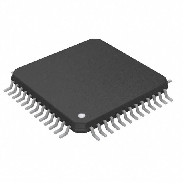
- Part No.:
- STFPC320BTR
- Manufacturer:
- STMicroelectronics
- Category:
- Power Management - Specialized
- Package:
- 52-QFP
- Datasheet:
-
 STFPC320BTR.pdf
- Description:
- IC CTLR/DVR FRONT PANEL 52QFP
- Quantity:
- Payment:

- Shipping:

Inventory:3,274
Please send an inquiry. Send us your inquiry, and we will respond immediately.
Product details
Overview
STFPC320BTR from STMicroelectronics is a front-panel controller/driver IC integrating VFD display driving (up to 20 segments × 8 digits), IR remote decoding (Philips RC-5, NEC, Sony, Matsushita), real-time clock (±25 sec/month accuracy), key scanning (12×2 matrix), and LED driving (4 channels, 20 mA each) - all programmable via I²C. It delivers standby power management to host systems and operates with dual supplies: VDD = 3.3 V and VSS down to –30 V, enabling direct high-voltage VFD anode drive in consumer AV equipment.
For engineers reviewing the STFPC320BTR datasheet, STFPC320BTR pinout, STFPC320BTR application, or STFPC320BTR equivalent, this device serves as a single-chip solution for front-panel control in legacy DVD/VCR/HTiB systems requiring integrated RTC, IR decode, dimming (8-step), and low-power standby wake-up capability.
Technical Context
The STFPC320BTR implements a fully integrated front-panel subsystem: its VFD driver uses P-channel open-drain + internal pull-down outputs eliminating external resistors; the RTC employs an internal oscillator with external 32.768 kHz crystal and supports alarm wake-up and ±25 sec/month accuracy. The IR decoder supports five protocols in both decoded and RAW formats, and keyscan logic handles debounced 24-key matrix input with interrupt-driven event reporting.
I²C interface operates at up to 400 kHz with standard 7-bit slave addressing; configuration, display RAM, RTC registers, and interrupt flags are all memory-mapped over the bus. Standby mode reduces current consumption significantly while retaining RTC operation and enabling wake-up via IR command, keypress, or alarm - managed through dedicated READY and MUTE pins.
Key Specifications
| Parameter | Value and Actual Design Meaning |
|---|---|
| VDD Supply | 3.3 V nominal - powers logic core and I²C interface; enables direct compatibility with 3.3 V system buses. |
| VSS Supply | Down to –30 V - provides negative rail for high-voltage VFD segment/cathode drive without external level shifters. |
| I²C Speed | Up to 400 kHz - supports fast register access and display data updates in real-time panel applications. |
| RTC Accuracy | ±25 seconds per month - achieved via temperature-compensated crystal oscillator and internal calibration register. |
| Display Capacity | Configurable up to 20 segments × 8 digits or 12 segments × 16 digits - supports diverse VFD layouts without hardware change. |
| Key Matrix | 12 × 2 (24 keys) with scan and debounce - eliminates need for external key controller or firmware polling overhead. |
| LED Drive | 4 independent channels, 20 mA max each - drives status LEDs directly without external drivers or current-limiting resistors. |
Pinout & Package
STFPC320BTR is housed in a PQFP-52 package (10 mm × 10 mm, 0.65 mm pitch), optimized for compact front-panel PCB layout and thermal dissipation in consumer enclosures.
| Pin/Terminal | Circuit Role | Design Meaning |
|---|---|---|
| VDD | Positive supply | 3.3 V logic and interface power; must be decoupled locally per datasheet guidelines. |
| VSS | Negative supply | –30 V rail for VFD cathode/segment drive; referenced to GND for high-side switching. |
| SCL / SDA | I²C serial interface | Bi-directional, 400 kHz-capable bus lines; require external pull-ups to VDD. |
| READY | Ready indicator output | Open-drain active-low signal indicating IC readiness after power-up or wake-up. |
| MUTE | Mute control input | Active-low input that disables VFD/LED outputs and enters low-power mute state. |
| IRIN | IR signal input | CMOS-compatible input for demodulated IR carrier (e.g., from TSOP receiver); supports multiple protocol timing windows. |
| KR0–KR11 | Key row scan outputs | Open-drain outputs driving key matrix rows; internally multiplexed during scan cycle. |
| KC0–KC1 | Key column inputs | CMOS inputs sensing column return; debounced and latched for interrupt generation. |
Key Features
| Feature | Design Value |
|---|---|
| No external resistors for VFD drive | P-channel open-drain + integrated pull-down eliminates discrete components and board space for segment drivers. |
| Multi-protocol IR decoder | Hardware-accelerated decode of Philips RC-5, NEC, Sony, Matsushita, and R2000 - reduces MCU firmware load and latency. |
| Programmable hotkeys | Assign IR commands or keypresses to trigger immediate actions (e.g., power toggle, menu launch) without host CPU intervention. |
| 8-step LED dimming | Software-controlled PWM-like intensity adjustment across all 4 LED channels - enables consistent visual feedback under varying ambient light. |
| Standby power management | Generates controlled power-down sequence for host chipset and maintains RTC operation - extends system-level energy efficiency. |
Applications
| VCR/DVD Front Panel | Home Theater in a Box (HTiB) |
|---|---|
Use Scenario: Real-time display of tape counter, playback status, time, and channel info on vacuum fluorescent display (VFD). IC Role / Device Role / Timing Role: Central front-panel controller managing VFD drive, IR command parsing, RTC-based timer functions, and key input handling. Use Value: Reduces BOM count by consolidating VFD driver, RTC, IR decoder, and key scanner into one IC - lowering assembly cost and improving reliability. |
Use Scenario: Unified control interface for audio/video source selection, volume, clock display, and sleep timer in compact HTiB units. IC Role / Device Role / Timing Role: RTC provides accurate wake-up alarm and time-of-day display; IR decoder enables multi-brand remote compatibility. Use Value: Enables OEMs to support global remote standards (NEC, Sony, RC-5) without firmware rework - accelerating regional product certification. |
| Personal Video Recorder (PVR) | Set-Top Box (STB) with Clock Feature |
Use Scenario: Display of recording schedule, elapsed time, remaining disk space, and real-time clock on front-panel VFD. IC Role / Device Role / Timing Role: Manages time-critical wake-up events (e.g., scheduled recording start) using RTC alarm interrupt and standby power sequencing. Use Value: Guarantees precise scheduling accuracy (±25 sec/month) without relying on unstable network time sync - critical for unattended recordings. |
Use Scenario: Front-panel clock, channel info, and status indicators (e.g., signal lock, recording active) in cable/satellite STBs. IC Role / Device Role / Timing Role: LED ports drive status indicators; keyscan handles front-panel navigation; I²C allows seamless integration with main SoC. Use Value: Offloads timing-sensitive tasks (RTC, IR decode, display refresh) from main processor - freeing CPU cycles for video decoding and UI rendering. |
Equivalent & Alternatives
The following parts are listed as comparable options for similar front-panel controller applications.
| Alternative Part | Technical Difference | Application Difference | Selection Advice |
|---|---|---|---|
| STFPC310BTR | Predecessor with identical PQFP-52 package but lacks RTC and alarm wake-up functionality; supports only 12×16 digit display mode. | Cannot replace STFPC320BTR in applications requiring real-time clock or alarm-triggered wake-up. | Select only if RTC and wake-up are unnecessary and cost reduction is prioritized over feature set. |
| MAX6955AUG+ | Dual-display driver (VFD + LED) with I²C interface, but no IR decoder, RTC, or keyscan; requires external crystal and external resistors for VFD drive. | Lacks integrated IR/RTC/keyscan - necessitates additional ICs and firmware complexity for full front-panel functionality. | Consider only when VFD/LED driving is primary requirement and system already includes separate IR/RTC solutions. |
Compared with STFPC320BTR, STFPC310BTR saves cost but sacrifices RTC and alarm capabilities, while MAX6955AUG+ offers higher VFD drive flexibility but increases BOM count and design effort due to missing subsystem integration.
Availability
STFPC320BTR is available at Aetrix Electronics and suitable for VCR, DVD player, and home theater in a box (HTiB) designs requiring stable component supply for legacy consumer electronics manufacturing and service replacement programs.
Supply support for STFPC320BTR includes scheduled delivery planning, volume procurement assistance, BOM continuity management, traceable sourcing, and lifecycle availability coordination for OEM customers, industrial embedded developers, connected-device designers, and electronics production programs.
Manufacturer
STMicroelectronics is a global semiconductor leader headquartered in Geneva, Switzerland, specializing in microcontrollers, analog ICs, power management, and automotive-grade components.
The STFPC320BTR belongs to ST's legacy consumer front-panel controller product line, designed specifically to consolidate VFD driving, IR decoding, RTC, and keyscan into a single chip for cost-sensitive, space-constrained AV equipment.
FAQ
What is the maximum VFD segment voltage the STFPC320BTR can drive?
The STFPC320BTR supports VSS down to –30 V relative to GND, enabling high-voltage VFD segment drive up to VDD – 33.3 V (i.e., ~36.3 V differential). This eliminates external high-voltage drivers and allows direct connection to common VFD anode configurations used in consumer AV equipment.
Does the STFPC320BTR require an external crystal for RTC operation?
Yes - the STFPC320BTR requires a 32.768 kHz external crystal connected between OSC1 and OSC2 pins for RTC operation. The internal oscillator circuit is designed exclusively for this frequency; no internal RC option exists, and crystal load capacitance must match datasheet-specified values (12.5 pF typical) for ±25 sec/month accuracy.
Can the STFPC320BTR drive both VFD and LEDs simultaneously?
Yes - the STFPC320BTR concurrently drives VFD segments/digits and four independent LED channels (20 mA max each). Its internal architecture separates VFD scan timing from LED PWM dimming control, allowing simultaneous operation without resource conflict or display flicker.
How does the STFPC320BTR handle IR remote commands from different manufacturers?
The STFPC320BTR hardware-decodes five IR protocols (Philips RC-5, NEC, Sony, Matsushita, R2000) in parallel. Each received command is stored in a dedicated register with protocol ID and decoded data bytes, enabling the host MCU to distinguish sources and execute appropriate actions without software protocol parsing.
STFPC320BTR Specifications
- Product attributes
- Attribute value
- Manufacturer:
- STMicroelectronics
- Series:
- -
- Package/Case:
- 52-QFP
- Packaging:
- Tape & Reel (TR)
- Product Status:
- Obsolete
- Applications:
- -
- Current - Supply:
- -
- Voltage - Supply:
- -
- Operating Temperature:
- -40°C ~ 85°C
- Grade:
- -
- Qualification:
- -
- Mounting Type:
- Surface Mount
- Supplier Device Package:
- 52-PQFP (10x10)
STFPC320BTR FAQ
1.How can I place an order for STFPC320BTR through Aetrix?
Please submit a Request for Quotation (RFQ) for STFPC320BTR on Aetrix. Our sales agent will provide a competitive quotation and guide you through the order confirmation once you accept the terms.
2.Are the price and stock information for STFPC320BTR reliable?
The price and inventory of STFPC320BTR are updated periodically and may fluctuate due to market conditions. Stock and pricing data are typically refreshed every 24 hours. Quotation validity for STFPC320BTR is usually 5 days.
3.What payment methods are accepted for STFPC320BTR?
We accept Wire Transfer, PayPal, Credit Card, Western Union, MoneyGram, and Escrow for STFPC320BTR transactions.
Note: Certain payment methods may incur a processing fee.
4.How is shipping managed for STFPC320BTR?
STFPC320BTR orders can be shipped via leading logistics carriers, including DHL, UPS, FedEx, TNT, or Registered Mail.
Once your STFPC320BTR order is processed, you will receive an email with the shipment details and tracking number.
Note: Tracking information may take up to 24 hours to appear. Express delivery typically takes 3–5 business days.
5.How can I obtain technical support or documentation for STFPC320BTR?
For technical support, including STFPC320BTR datasheets, pinout diagrams, or application guidance, please contact our engineering support team. They can provide detailed documentation and assistance for your STFPC320BTR requirements.
6.How does Aetrix verify that STFPC320BTR is sourced from the original manufacturer or authorized distributors?
All STFPC320BTR products on Aetrix are procured from qualified distributors and authorized channels. Our dedicated quality assurance team conducts strict verification, including traceability checks and, if necessary, third-party testing. This ensures that STFPC320BTR meets industry standards.
7.What is the process for return or replacement of STFPC320BTR?
All STFPC320BTR units undergo pre-shipment inspection (PSI). If there is an issue with STFPC320BTR, returns or replacements are accepted under the following conditions:
1.Quantity discrepancies, incorrect items, or visible external defects (such as breakage or corrosion), acknowledged by Aetrix.
2.The issue is reported within 90 days of delivery.
3.The STFPC320BTR part is unused and in its original packaging.
Return procedure for STFPC320BTR:
1.Submit a request within 90 days.
2.Obtain a Return Material Authorization (RMA) from Aetrix.
STFPC320BTR Tags

-
TPS2511DGNR
Texas Instruments

-
UTC2000/MG
Microchip Technology

-
TUSB320HAIRWBR
Texas Instruments

-
TPS61252DSGR
Texas Instruments

-
PI5USB30216CXUAEX
Diodes Incorporated

-
SN6501DBVR
Texas Instruments

-
CYPD3177-24LQXQT
Infineon Technologies
-
SN6501QDBVRQ1
Texas Instruments

-
STUSB1600AQTR
STMicroelectronics

-
SN6505BDBVR
Texas Instruments
-
SN6501DBVT
Texas Instruments

-
TPS65150PWPR
Texas Instruments
Tech Hub

A practical engineering guide to 3.3V and 5V logic compatibility, input thresholds, resistor dividers, translator ICs, MOSFET level shifting, I2C pull-ups, timing limits and power-sequencing risks.

The 74HC595 uses push-pull logic outputs, while the TPIC6B595 uses 50 V open-drain DMOS sinks for higher-power loads. This guide compares timing, current limits, 3.3 V interfacing, load wiring, thermal…

The 74HC595 converts serial data into eight stable parallel outputs. This guide covers pin functions, shift and storage timing, OE and MR behavior, drive-current limits, cascading, voltage compatibilit…

A technical comparison of level-sensitive latches and edge-triggered flip-flops, covering timing windows, setup and hold limits, master–slave operation, time borrowing, race-through, HDL inference and…

A D latch stores one bit while Enable controls when data can pass. This reference covers gate-level operation, truth tables, transparency, setup and hold timing, LE versus OE, common ICs and practical …

An SR latch stores one bit through cross-coupled feedback. This engineering reference covers NOR and NAND implementations, truth tables, forbidden-state recovery, gated operation, switch debouncing, fa…

Latch circuits retain one bit through feedback. This technical reference covers SR and D latches, truth tables, transparency, timing limits, latch-versus-flip-flop behavior, applications and common log…

An engineering guide to LED driver operation, constant-current and constant-voltage outputs, linear and switching topologies, dimming, IC selection, calculations, replacement compatibility, and fault c…

Operational amplifier guide covering op amp basics, feedback, ideal vs real op amps, common configurations, buffer circuits, offset, bias current, gain-bandwidth, slew rate, rail-to-rail limits and sel…

Jumper cables guide covering safe connection order, red and black clamp placement, final ground connection, cable gauge, length, clamp quality, copper vs CCA cables, jump starter comparison and battery…


