
 My Inquiry
 My Account


STMicroelectronics STLUX385
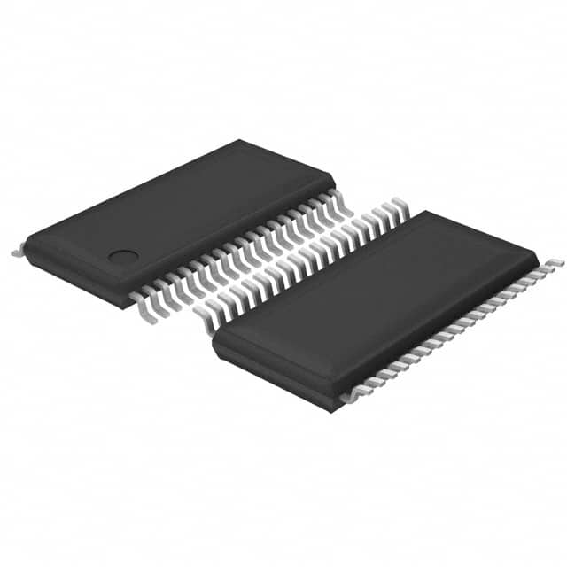
- Part No.:
- STLUX385
- Manufacturer:
- STMicroelectronics
- Category:
- Power Management - Specialized
- Package:
- 38-TFSOP (0.173", 4.40mm Width)
- Datasheet:
-
 STLUX385.pdf
- Description:
- IC DIGITAL CTLR 38TSSOP
- Quantity:
- Payment:

- Shipping:

Inventory:2,843
Please send an inquiry. Send us your inquiry, and we will respond immediately.
Product details
Overview
STLUX385 from STMicroelectronics is a digital controller IC for lighting and power supply systems, integrating an enhanced STM8 core (16 MHz max CPU), 6 independent SMED-based PWM generators, 96 MHz PLL, DALI interface, and a gain-programmable 10-bit ADC with op-amp extension to 12-bit effective resolution. It targets LED drivers, fluorescent ballasts, and HID lamp control.
For engineers reviewing the STLUX385 datasheet, STLUX385 pinout, STLUX385 application, or STLUX385 equivalent, key selection considerations include its DALI target device compliance, six programmable PWM channels with event-driven state machines, 50 ns analog comparator propagation delay, and TSSOP38 package compatibility with high-density lighting control PCB layouts.
Technical Context
The STLUX385 implements a Harvard-architecture STM8 core with 3-stage pipeline and 24-bit linear addressing, supporting non-intrusive debugging via SWIM single-wire interface. Its clock system combines internal 16 MHz and 153.6 kHz RC oscillators, external crystal support up to 24 MHz, and a user-configurable 96 MHz PLL for precise PWM timing.
Peripheral integration centers on six SMED units-state-machine event-driven PWM generators-with a programmable connection box enabling complex timer topologies. The DALI hardware cell handles physical layer signaling and protocol framing per IEC 62386-102, while four 4-bit DACs feed internal reference voltages to analog comparators with 50 ns max cycle time.
Key Specifications
| Parameter | Value and Actual Design Meaning |
|---|---|
| CPU Core | Enhanced STM8 CISC core with 3-stage pipeline, 16 MHz max operation for deterministic real-time lighting control. |
| PWM Generators | 6 independent SMED units-event-driven, state-machine-based PWM signal generators with flexible trigger and sequencing. |
| DALI Interface | Integrated DALI target device hardware cell compliant with IEC 62386-102, eliminating external transceiver components. |
| ADC Resolution | 10-bit SAR ADC with 8 multiplexed inputs; op-amp gain options (x1.6/x6.4) extend effective resolution to 12-bit for current sensing. |
| Analog Comparators | 4 internal comparators with programmable 4-bit DAC references + 1 comparator with external reference; 50 ns max propagation delay. |
| Memory | 32 KB Flash (15 yr data retention at 85 °C after 10k cycles); 1 KB true EEPROM (15 yr retention at 85 °C after 100k cycles). |
| Operating Temp | -25 °C to +105 °C ambient range, qualified for industrial-grade lighting and power supply environments. |
Pinout & Package
TSSOP38 package (9.7 mm × 6.4 mm × 1.05 mm height), RoHS-compliant ECOPACK® grade, with exposed pad not present. Pin count: 38 leads, 0.5 mm pitch, dual-row surface-mount.
| Pin/Terminal | Circuit Role | Design Meaning |
|---|---|---|
| 1, 4–5, 8, 16, 19 | GPIO1[n]/PWM[n] | Primary PWM output terminals for SMED0–SMED5; also serve as general-purpose I/O with configurable pull-up/down. |
| 14–15 | GPIO0[4]/DALI_TX, GPIO0[5]/DALI_RX | Dedicated DALI physical layer interface pins-drive/receive differential bus signals without external transceiver. |
| 20–23 | GPIO0[0–3]/UART/I²C/HSE | Multiplexed communication interfaces: UART TX/RX, I²C SDA/SCL, and HSE oscillator input/output for clock flexibility. |
| 24–28, 26 | CPP[0–3], CPM3 | Analog comparator inputs: 4 positive (CPP) and 1 negative (CPM3) terminals tied to internal 4-bit DAC reference network. |
| 31–38 | ADCIN[0–7] | Eight dedicated analog input channels for voltage/current feedback, supporting sequential conversion and op-amp gain configuration. |
| 9 | SWIM | Single-wire interface for non-intrusive in-circuit debugging and ultra-fast Flash programming. |
| 10 | NRST | Active-low reset input with internal pull-up; supports both external reset assertion and software-initiated reset. |
Key Features
| Feature | Design Value |
|---|---|
| SMED-based PWM architecture | Six independent, event-triggered state machines enable synchronized multi-channel switching for resonant half-bridge and full-bridge topologies. |
| DALI hardware cell | On-die DALI PHY and MAC eliminate need for external transceiver ICs, reducing BOM cost and board space in smart ballast designs. |
| Programmable ADC gain | Configurable x1.6 or x6.4 op-amp gain per channel extends dynamic range-critical for accurate LED current regulation across dimming ranges. |
| High-speed analog comparators | 50 ns max propagation delay enables cycle-by-cycle overcurrent protection in switch-mode power stages without external fast comparators. |
| Robust memory reliability | Flash and EEPROM include ECC and guaranteed 15-year data retention at 85 °C-validated for long-lifecycle lighting infrastructure deployments. |
Applications
| LED Driver Control | Fluorescent Ballast |
|---|---|
Use Scenario: Constant-current dimmable LED driver for commercial downlights using buck or buck-boost topology. IC Role / Device Role / Timing Role: Primary digital controller managing PWM dimming, thermal foldback, and open/short-circuit protection via ADC and comparators. Use Value: Integrated 6-channel PWM and DALI interface enable single-chip control of multi-string LED arrays with standardized digital dimming commands. | Use Scenario: Electronic ballast for T5/T8 fluorescent lamps with phase-cut dimming and end-of-life detection. IC Role / Device Role / Timing Role: System-on-chip controller executing resonant half-bridge gate drive, filament preheat timing, and lamp ignition sequence. Use Value: SMED units generate precisely timed, interlocked PWM pairs for zero-voltage switching; DALI allows remote lamp status reporting and group-level dimming. |
| HID Lamp Ballast | Power Factor Correction |
Use Scenario: High-intensity discharge (HID) lamp ballast for street lighting requiring hot restrike and acoustic resonance avoidance. IC Role / Device Role / Timing Role: Full-bridge PWM controller with frequency sweeping and adaptive dead-time control managed by SMED logic blocks. Use Value: 96 MHz PLL delivers sub-nanosecond PWM edge resolution for fine-tuned frequency modulation-critical to suppress acoustic noise in HID lamps. | Use Scenario: Active PFC stage in LED streetlight power supplies operating in continuous conduction mode (CCM). IC Role / Device Role / Timing Role: Digital PFC controller implementing average current mode control using ADC-sampled line voltage and inductor current. Use Value: 10-bit ADC with op-amp gain and 8-channel sequencing allow simultaneous sampling of AC line, DC bus, and boost current-enabling tight THD control. |
Equivalent & Alternatives
The following parts are listed as comparable options for similar digital lighting controller applications.
| Alternative Part | Technical Difference | Application Difference | Selection Advice |
|---|---|---|---|
| STLUX385A | Pin-compatible revision with improved ESD immunity (±8 kV HBM) and updated internal oscillator trimming algorithm. | Same DALI and SMED functionality; validated for new production runs requiring higher robustness in factory handling. | Select STLUX385A for new designs where enhanced manufacturing yield and field reliability under electrostatic stress are prioritized. |
| IRS2540SPBF | Analog HV half-bridge driver with integrated bootstrap diode and no MCU, DALI, or ADC-requires external microcontroller for digital control. | Limited to fixed-frequency or simple analog dimming; lacks programmable PWM, DALI, or digital protection features. | Choose IRS2540SPBF only for cost-sensitive, non-DALI fluorescent ballasts where digital intelligence is implemented externally. |
Compared with STLUX385, the STLUX385A offers verified improvements in ESD tolerance without functional change, while the IRS2540SPBF provides only gate-driving capability-requiring separate MCU, communication IC, and signal conditioning for equivalent system functionality.
Availability
STLUX385 is available at Aetrix Electronics and suitable for LED driver control, fluorescent ballast design, and HID lamp ballast development requiring stable component supply and long-term industrial lifecycle support.
Supply support for STLUX385 includes scheduled delivery planning, volume procurement assistance, BOM continuity management, traceable sourcing, and lifecycle availability coordination for OEM customers, industrial embedded developers, connected-device designers, and electronics production programs.
Manufacturer
STMicroelectronics is a global semiconductor leader headquartered in Geneva, Switzerland, designing and manufacturing microcontrollers, power ICs, sensors, and analog products for industrial, automotive, and consumer markets.
The STLUX series targets intelligent lighting control, combining STM8 processing with application-specific peripherals like DALI, SMED PWM, and high-speed analog front-ends to replace discrete analog controllers in solid-state lighting systems.
FAQ
What is the maximum operating frequency of the STLUX385's internal PLL?
The STLUX385 integrates a user-configurable 96 MHz PLL used to derive high-resolution timing for its six SMED PWM generators. This PLL operates independently of the 16 MHz CPU clock and enables sub-nanosecond PWM edge placement precision, critical for resonant converter control and acoustic noise suppression in HID lamps.
Does the STLUX385 require an external DALI transceiver?
No. The STLUX385 includes a fully integrated DALI hardware cell compliant with IEC 62386-102, supporting both physical layer signaling and protocol framing. Pins 14 (DALI_TX) and 15 (DALI_RX) connect directly to the DALI bus through standard current-limiting resistors and transient protection-no external transceiver IC is needed.
How many analog inputs does the STLUX385 ADC support, and what is its effective resolution?
The STLUX385 ADC supports eight analog input channels (ADCIN[0]–ADCIN[7]) with 10-bit SAR conversion. When configured with the internal operational amplifier, selectable gain settings (x1.6 or x6.4) extend the effective resolution to 12 bits, enabling precise current sensing across wide dynamic ranges in LED driver and PFC applications.
What debug interface does the STLUX385 provide, and is it compatible with standard tools?
The STLUX385 uses the SWIM (Single-Wire Interface Module) debug interface, a proprietary ST protocol accessible via ST-LINK/V2 or compatible programmers. It supports non-intrusive real-time debugging, flash programming, and memory inspection without requiring additional pins or JTAG headers-fully supported by STM8CubeIDE and ST's official toolchain.
STLUX385 Specifications
- Product attributes
- Attribute value
- Manufacturer:
- STMicroelectronics
- Series:
- -
- Package/Case:
- 38-TFSOP (0.173", 4.40mm Width)
- Packaging:
- Tube
- Product Status:
- Active
- Applications:
- Lighting
- Current - Supply:
- -
- Voltage - Supply:
- 3V ~ 5.5V
- Operating Temperature:
- -40°C ~ 105°C
- Grade:
- -
- Qualification:
- -
- Mounting Type:
- Surface Mount
- Supplier Device Package:
- 38-TSSOP
STLUX385 FAQ
1.How can I place an order for STLUX385 through Aetrix?
Please submit a Request for Quotation (RFQ) for STLUX385 on Aetrix. Our sales agent will provide a competitive quotation and guide you through the order confirmation once you accept the terms.
2.Are the price and stock information for STLUX385 reliable?
The price and inventory of STLUX385 are updated periodically and may fluctuate due to market conditions. Stock and pricing data are typically refreshed every 24 hours. Quotation validity for STLUX385 is usually 5 days.
3.What payment methods are accepted for STLUX385?
We accept Wire Transfer, PayPal, Credit Card, Western Union, MoneyGram, and Escrow for STLUX385 transactions.
Note: Certain payment methods may incur a processing fee.
4.How is shipping managed for STLUX385?
STLUX385 orders can be shipped via leading logistics carriers, including DHL, UPS, FedEx, TNT, or Registered Mail.
Once your STLUX385 order is processed, you will receive an email with the shipment details and tracking number.
Note: Tracking information may take up to 24 hours to appear. Express delivery typically takes 3–5 business days.
5.How can I obtain technical support or documentation for STLUX385?
For technical support, including STLUX385 datasheets, pinout diagrams, or application guidance, please contact our engineering support team. They can provide detailed documentation and assistance for your STLUX385 requirements.
6.How does Aetrix verify that STLUX385 is sourced from the original manufacturer or authorized distributors?
All STLUX385 products on Aetrix are procured from qualified distributors and authorized channels. Our dedicated quality assurance team conducts strict verification, including traceability checks and, if necessary, third-party testing. This ensures that STLUX385 meets industry standards.
7.What is the process for return or replacement of STLUX385?
All STLUX385 units undergo pre-shipment inspection (PSI). If there is an issue with STLUX385, returns or replacements are accepted under the following conditions:
1.Quantity discrepancies, incorrect items, or visible external defects (such as breakage or corrosion), acknowledged by Aetrix.
2.The issue is reported within 90 days of delivery.
3.The STLUX385 part is unused and in its original packaging.
Return procedure for STLUX385:
1.Submit a request within 90 days.
2.Obtain a Return Material Authorization (RMA) from Aetrix.
STLUX385 Tags

-
TPS2511DGNR
Texas Instruments

-
UTC2000/MG
Microchip Technology

-
TUSB320HAIRWBR
Texas Instruments

-
TPS61252DSGR
Texas Instruments

-
PI5USB30216CXUAEX
Diodes Incorporated

-
SN6501DBVR
Texas Instruments

-
CYPD3177-24LQXQT
Infineon Technologies
-
SN6501QDBVRQ1
Texas Instruments

-
STUSB1600AQTR
STMicroelectronics

-
SN6505BDBVR
Texas Instruments
-
SN6501DBVT
Texas Instruments

-
TPS65150PWPR
Texas Instruments
Tech Hub

A practical engineering and sourcing framework covering lifecycle verification, lifetime-buy calculations, replacement qualification, supplier checks and counterfeit-risk controls.

TTL and CMOS logic families differ in thresholds, loading, output drive, power and timing. This engineering guide compares 74HC and 74HCT, calculates noise margins and checks 3.3 V/5 V compatibility.

A practical engineering guide to 3.3V and 5V logic compatibility, input thresholds, resistor dividers, translator ICs, MOSFET level shifting, I2C pull-ups, timing limits and power-sequencing risks.

The 74HC595 uses push-pull logic outputs, while the TPIC6B595 uses 50 V open-drain DMOS sinks for higher-power loads. This guide compares timing, current limits, 3.3 V interfacing, load wiring, thermal…

The 74HC595 converts serial data into eight stable parallel outputs. This guide covers pin functions, shift and storage timing, OE and MR behavior, drive-current limits, cascading, voltage compatibilit…

A technical comparison of level-sensitive latches and edge-triggered flip-flops, covering timing windows, setup and hold limits, master–slave operation, time borrowing, race-through, HDL inference and…

A D latch stores one bit while Enable controls when data can pass. This reference covers gate-level operation, truth tables, transparency, setup and hold timing, LE versus OE, common ICs and practical …

An SR latch stores one bit through cross-coupled feedback. This engineering reference covers NOR and NAND implementations, truth tables, forbidden-state recovery, gated operation, switch debouncing, fa…

Latch circuits retain one bit through feedback. This technical reference covers SR and D latches, truth tables, transparency, timing limits, latch-versus-flip-flop behavior, applications and common log…

An engineering guide to LED driver operation, constant-current and constant-voltage outputs, linear and switching topologies, dimming, IC selection, calculations, replacement compatibility, and fault c…


