
 My Inquiry
 My Account


STMicroelectronics STNRGPF12
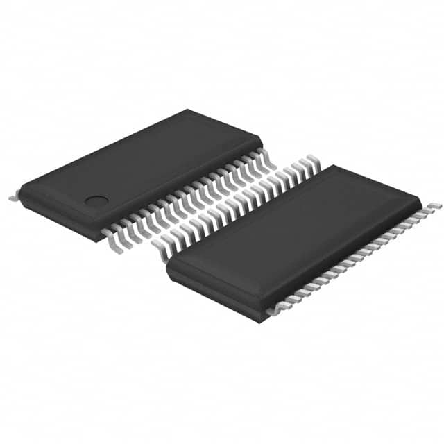
- Part No.:
- STNRGPF12
- Manufacturer:
- STMicroelectronics
- Category:
- Power Management - Specialized
- Package:
- 38-TFSOP (0.173", 4.40mm Width)
- Datasheet:
-
 STNRGPF12.pdf
- Description:
- TWO-CHANNEL INTERLEAVED CCM PFC
- Quantity:
- Payment:

- Shipping:

Inventory:2,063
Please send an inquiry. Send us your inquiry, and we will respond immediately.
Product details
Overview
STNRGPF12 from STMicroelectronics is a digital 2-channel interleaved CCM boost PFC controller with embedded digital inrush current limiter for semi-controlled bridge topologies, fixed 65–250 kHz switching frequency, average current mode control, and -40 °C to 105 °C operating range - deployed in >600 W industrial UPS, welding equipment, and air conditioner power supplies.
For engineers reviewing the STNRGPF12 datasheet, STNRGPF12 pinout, STNRGPF12 application, or STNRGPF12 equivalent, key selection considerations include its mixed-signal (analog inner current loop + digital outer voltage loop) architecture, programmable phase shedding, dual-channel current balance, UART-based configuration via eDesignSuite, and dedicated SCR gate drive capability for controlled-bridge inrush management.
Technical Context
The STNRGPF12 implements a cascaded mixed-signal control architecture: the analog PI current compensator (pins 24/25) regulates total input current against a digitally generated sinusoidal reference, while the digital PI voltage controller computes peak current reference using input voltage feedforward (pins 31/38) and load feedforward (pin 33). This enables fast transient response to line and load steps without output voltage deviation exceeding ±2%.
Its interleaving engine generates two PWM outputs (pins 1 and 16) with precise 180° phase shift, synchronized by internal clock (pin 2) and SET generator logic. The device supports burst-mode operation post-startup (pin 15 PFC_OK low), fan control signaling (pin 20), and real-time monitoring of channel currents (pins 35/36), output voltage (pin 34), and ambient temperature (pin 32).
Key Specifications
| Parameter | Value and Actual Design Meaning |
|---|---|
| Topology Support | 2-channel interleaved CCM boost PFC with 180° phase shift - reduces EMI filter size and capacitor RMS current by ~30% vs single-phase. |
| Switching Frequency | 65–250 kHz fixed-frequency operation - enables predictable EMI filtering and thermal design with standard ferrite cores. |
| Inrush Control Method | Digital semi-controlled bridge drive (SCR/IGBT) - modulates conduction timing to limit peak inrush without external relay or thermistor. |
| Memory Resources | 32 KB flash (15-yr retention at 85 °C), 1 KB true EEPROM (100 kcycles @ 85 °C), 6 KB RAM - supports field firmware updates and parameter storage. |
| Protection Features | Programmable fast overcurrent (COMP0/1), thermal shutdown (pin 32), overvoltage (pin 34), and PFC fault signaling (pin 14) - enables fail-safe system-level coordination. |
| Interface | UART asynchronous port - used for bootloader programming, real-time parameter monitoring, and binary configuration download via STSW-STNRGPF01. |
| Operating Temperature | -40 °C to +105 °C ambient - qualified for industrial motor drives and outdoor UPS enclosures without derating. |
Pinout & Package
TSSOP38 package (9.7 mm × 4.4 mm, 0.65 mm pitch) with exposed thermal pad - provides enhanced thermal dissipation for high-power PFC applications and compatibility with standard reflow profiles.
| Pin/Terminal | Circuit Role | Design Meaning |
|---|---|---|
| 1, 16 | PWM[0], PWM[1] | Complementary 180°-phase-shifted gate drive outputs for CH[0]/CH[1] power switches - directly interface with external MOSFET/IGBT drivers. |
| 2 | CLOCK | 50% duty-cycle clock at selected switching frequency - synchronizes internal PWM generation and enables external triangle waveform synthesis. |
| 24, 25 | OUT_PI[3], OUT_PI[2] | Analog PI current compensator outputs - feed COMP2/COMP3 comparators to generate master PWM duty cycle with sub-μs latency. |
| 31, 38 | Vin_L1, AVin_L2 | Dedicated AC line voltage sensing inputs - enable RMS calculation, sinusoidal current reference generation, and input voltage feedforward compensation. |
| 34 | Vout | Output voltage feedback input - connects to resistive divider for precise regulation and overvoltage protection threshold detection. |
| 14, 15 | PFC_FAULT, PFC_OK | Open-drain status indicators - PFC_FAULT asserts low on fault; PFC_OK pulls low when output reaches Vout_ref and system enters burst mode. |
Key Features
| Feature | Design Value |
|---|---|
| Embedded digital inrush limiter | Direct SCR/IGBT gate control for semi-controlled bridge - eliminates need for mechanical relays, NTCs, or bypass FETs in >600 W systems. |
| Channel current balancing | Real-time measurement of ICH[0]/ICH[1] (pins 35/36) with automatic duty adjustment - maintains ≤3% current mismatch between phases under dynamic load. |
| Programmable phase shedding | Single-channel operation below 50% load threshold - reduces switching losses and improves light-load efficiency by up to 2.1% at 10% load. |
| eDesignSuite configurability | GUI-driven parameter entry (input voltage range, output voltage, power level) → auto-generates schematic, BOM, and flashable binary - cuts firmware development time by ~70%. |
| Burst mode with dual thresholds | Vburst_min/Vburst_max set during configuration - enables zero-load hold with <150 mW standby consumption while maintaining ready-to-load state. |
Applications
| Industrial UPS Systems | Air Conditioner Power Stages |
|---|---|
|
Use Scenario: Three-phase 10 kVA online UPS with active PFC front-end handling grid transients and battery recharge surges. IC Role / Device Role / Timing Role: Dual-channel interleaved PFC controller managing 2× boost stages, coordinating inrush limiting during cold start and load step recovery. Use Value: Reduces input filter inductor volume by 40% and achieves THD <5% at full load while sustaining 105 °C ambient operation. |
Use Scenario: Inverter-driven HVAC compressor power supply requiring stable DC bus under variable-speed motor loads and frequent on/off cycling. IC Role / Device Role / Timing Role: Digital PFC manager executing soft-start, burst-mode no-load hold, and phase-shedding during low-capacity cooling cycles. Use Value: Enables 96.2% peak efficiency and <3% output voltage deviation during 100 A load steps, validated per IEC 61000-3-2 Class A. |
| Industrial Welding Equipment | High-Power Battery Chargers |
|
Use Scenario: 12 kW arc welder with intermittent duty cycle, demanding robust inrush control during electrode stick events and rapid voltage recovery. IC Role / Device Role / Timing Role: Interleaved PFC controller with digital inrush limiter driving SCRs to clamp inrush to <25 A peak during repeated hot starts. Use Value: Eliminates relay contact welding failures and extends primary capacitor life by 3× versus resistor-based limiter solutions. |
Use Scenario: 7.2 kW EV DC fast charger front-end managing wide-input AC (90–264 VAC) and dynamic DC bus loading during constant-current charging phases. IC Role / Device Role / Timing Role: Configurable PFC controller implementing input voltage feedforward and load feedforward to maintain ±0.5% Vout regulation across 0–100% load. Use Value: Achieves >98% efficiency at 50% load and meets EN 61000-3-12 harmonic limits without auxiliary filters. |
Equivalent & Alternatives
The following parts are listed as comparable options for similar interleaved PFC controller applications.
| Alternative Part | Technical Difference | Application Difference | Selection Advice |
|---|---|---|---|
| UCC28070 | Analog dual-channel CCM controller with no embedded inrush limiter; requires external circuitry for SCR control and no UART configuration interface. | Lacks digital inrush management and programmable burst mode - suitable only where discrete inrush solution is acceptable and firmware customization is unnecessary. | Select UCC28070 only if legacy analog design flow is mandated and inrush is handled externally with relays or thermistors. |
| ICE3PCS01G | Single-channel digital PFC IC with basic inrush support (resistor bypass only); no interleaving, no phase shedding, and no dual-channel current sensing. | Cannot scale beyond ~400 W due to single-stage topology; unsuitable for >600 W applications requiring EMI reduction and thermal distribution. | Choose ICE3PCS01G only for cost-sensitive, lower-power (<400 W) designs where interleaving benefits are not required. |
Compared with UCC28070 and ICE3PCS01G, STNRGPF12 uniquely integrates digital semi-controlled bridge inrush control, 2-channel interleaving with automatic current balancing, and full-field programmability - enabling compact, high-reliability >600 W PFC designs without external component overhead.
Availability
STNRGPF12 is available at Aetrix Electronics and suitable for industrial UPS systems, air conditioner power stages, and high-power battery chargers requiring stable component supply, long-term lifecycle assurance, and traceable sourcing for production ramp.
Supply support for STNRGPF12 includes scheduled delivery planning, volume procurement assistance, BOM continuity management, traceable sourcing, and lifecycle availability coordination for OEM customers, industrial embedded developers, connected-device designers, and electronics production programs.
Manufacturer
STMicroelectronics is a global semiconductor leader headquartered in Geneva, specializing in power management, microcontrollers, and analog ICs for industrial, automotive, and consumer markets.
STNRGPF12 belongs to ST's STNRG digital PFC controller product line, engineered specifically for high-efficiency, high-reliability interleaved boost converters in >600 W industrial power supplies.
FAQ
What distinguishes STNRGPF12's inrush current limiter from STNRGPF02's?
STNRGPF12 implements a digital semi-controlled bridge method using SCR/IGBT gate drive (pins 1/16 modulated with progressive phase shift), eliminating external relays and thermistors. STNRGPF02 uses a simpler resistor-bypass approach (pin 21 high to short R), requiring mechanical switching and offering no dynamic inrush adaptation. STNRGPF12's method enables smoother capacitor charging, lower stress on input components, and higher reliability in repetitive hot-start scenarios.
How does STNRGPF12 achieve current balance between its two PFC channels?
STNRGPF12 measures individual channel currents via dedicated pins 35 (ICH[0]) and 36 (ICH[1]), processes them through an internal low-pass filter matched to switching frequency, and dynamically adjusts PWM duty cycles to maintain ≤3% current mismatch. This real-time hardware-based balancing operates independently of the digital voltage loop and ensures equal thermal loading across both boost stages under all load conditions.
Can STNRGPF12 operate without the eDesignSuite configuration tool?
No - STNRGPF12 requires initial configuration via ST's eDesignSuite software to generate the application-specific binary file loaded through UART. The device ships unprogrammed; without this step, it remains in reset state and produces no PWM outputs. Pre-configured binaries are not offered, as parameters like input voltage range, output voltage, and burst thresholds must be tailored to each end-equipment design.
What thermal management features does STNRGPF12 provide for industrial environments?
STNRGPF12 monitors ambient temperature via pin 32 (Temp), triggering immediate PWM disable if voltage drops below the user-defined threshold (corresponding to ~105 °C board temperature). It also provides active fan control via pin 20 (FAN), which asserts low when power exceeds a configurable level - enabling closed-loop thermal management without external microcontroller intervention.
STNRGPF12 Specifications
- Product attributes
- Attribute value
- Manufacturer:
- STMicroelectronics
- Series:
- -
- Package/Case:
- 38-TFSOP (0.173", 4.40mm Width)
- Packaging:
- Tape & Reel (TR)
- Product Status:
- Obsolete
- Applications:
- Digital Power Controller
- Current - Supply:
- -
- Voltage - Supply:
- -
- Operating Temperature:
- -40°C ~ 105°C
- Grade:
- -
- Qualification:
- -
- Mounting Type:
- Surface Mount
- Supplier Device Package:
- 38-TSSOP
STNRGPF12 FAQ
1.How can I place an order for STNRGPF12 through Aetrix?
Please submit a Request for Quotation (RFQ) for STNRGPF12 on Aetrix. Our sales agent will provide a competitive quotation and guide you through the order confirmation once you accept the terms.
2.Are the price and stock information for STNRGPF12 reliable?
The price and inventory of STNRGPF12 are updated periodically and may fluctuate due to market conditions. Stock and pricing data are typically refreshed every 24 hours. Quotation validity for STNRGPF12 is usually 5 days.
3.What payment methods are accepted for STNRGPF12?
We accept Wire Transfer, PayPal, Credit Card, Western Union, MoneyGram, and Escrow for STNRGPF12 transactions.
Note: Certain payment methods may incur a processing fee.
4.How is shipping managed for STNRGPF12?
STNRGPF12 orders can be shipped via leading logistics carriers, including DHL, UPS, FedEx, TNT, or Registered Mail.
Once your STNRGPF12 order is processed, you will receive an email with the shipment details and tracking number.
Note: Tracking information may take up to 24 hours to appear. Express delivery typically takes 3–5 business days.
5.How can I obtain technical support or documentation for STNRGPF12?
For technical support, including STNRGPF12 datasheets, pinout diagrams, or application guidance, please contact our engineering support team. They can provide detailed documentation and assistance for your STNRGPF12 requirements.
6.How does Aetrix verify that STNRGPF12 is sourced from the original manufacturer or authorized distributors?
All STNRGPF12 products on Aetrix are procured from qualified distributors and authorized channels. Our dedicated quality assurance team conducts strict verification, including traceability checks and, if necessary, third-party testing. This ensures that STNRGPF12 meets industry standards.
7.What is the process for return or replacement of STNRGPF12?
All STNRGPF12 units undergo pre-shipment inspection (PSI). If there is an issue with STNRGPF12, returns or replacements are accepted under the following conditions:
1.Quantity discrepancies, incorrect items, or visible external defects (such as breakage or corrosion), acknowledged by Aetrix.
2.The issue is reported within 90 days of delivery.
3.The STNRGPF12 part is unused and in its original packaging.
Return procedure for STNRGPF12:
1.Submit a request within 90 days.
2.Obtain a Return Material Authorization (RMA) from Aetrix.
STNRGPF12 Tags

-
TPS2511DGNR
Texas Instruments

-
UTC2000/MG
Microchip Technology

-
TUSB320HAIRWBR
Texas Instruments

-
TPS61252DSGR
Texas Instruments

-
PI5USB30216CXUAEX
Diodes Incorporated

-
SN6501DBVR
Texas Instruments

-
CYPD3177-24LQXQT
Infineon Technologies
-
SN6501QDBVRQ1
Texas Instruments

-
STUSB1600AQTR
STMicroelectronics

-
SN6505BDBVR
Texas Instruments
-
SN6501DBVT
Texas Instruments

-
TPS65150PWPR
Texas Instruments
Tech Hub

A practical engineering and sourcing framework covering lifecycle verification, lifetime-buy calculations, replacement qualification, supplier checks and counterfeit-risk controls.

TTL and CMOS logic families differ in thresholds, loading, output drive, power and timing. This engineering guide compares 74HC and 74HCT, calculates noise margins and checks 3.3 V/5 V compatibility.

A practical engineering guide to 3.3V and 5V logic compatibility, input thresholds, resistor dividers, translator ICs, MOSFET level shifting, I2C pull-ups, timing limits and power-sequencing risks.

The 74HC595 uses push-pull logic outputs, while the TPIC6B595 uses 50 V open-drain DMOS sinks for higher-power loads. This guide compares timing, current limits, 3.3 V interfacing, load wiring, thermal…

The 74HC595 converts serial data into eight stable parallel outputs. This guide covers pin functions, shift and storage timing, OE and MR behavior, drive-current limits, cascading, voltage compatibilit…

A technical comparison of level-sensitive latches and edge-triggered flip-flops, covering timing windows, setup and hold limits, master–slave operation, time borrowing, race-through, HDL inference and…

A D latch stores one bit while Enable controls when data can pass. This reference covers gate-level operation, truth tables, transparency, setup and hold timing, LE versus OE, common ICs and practical …

An SR latch stores one bit through cross-coupled feedback. This engineering reference covers NOR and NAND implementations, truth tables, forbidden-state recovery, gated operation, switch debouncing, fa…

Latch circuits retain one bit through feedback. This technical reference covers SR and D latches, truth tables, transparency, timing limits, latch-versus-flip-flop behavior, applications and common log…

An engineering guide to LED driver operation, constant-current and constant-voltage outputs, linear and switching topologies, dimming, IC selection, calculations, replacement compatibility, and fault c…


