
 My Inquiry
 My Account


STMicroelectronics ST-ONETR
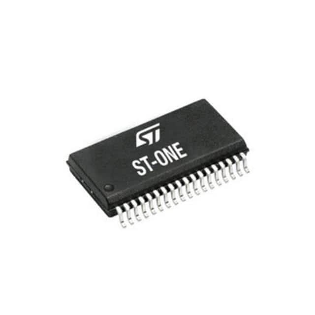
- Part No.:
- ST-ONETR
- Manufacturer:
- STMicroelectronics
- Category:
- Power Management - Specialized
- Package:
- 36-BSOP (0.295", 7.50mm Width)
- Datasheet:
-
 ST-ONETR.pdf
- Description:
- FULLY INTEGRATED CONTROLLER FOR
- Quantity:
- Payment:

- Shipping:

Inventory:893
Please send an inquiry. Send us your inquiry, and we will respond immediately.
Product details
Overview
ST-ONETR from STMicroelectronics is a fully integrated digital controller for smart USB-PD chargers and adapters. The IC combines an Arm Cortex-M0+ core, an offline programmable active-clamp flyback controller, synchronous-rectification control, USB-PD PHY, high-voltage startup circuitry, isolated primary-to-secondary communication, and preloaded firmware in a single SSOP36L package.
For engineers reviewing the ST-ONETR datasheet, ST-ONETR pinout, ST-ONETR application, or ST-ONETR equivalent, this controller is most relevant for high-density USB-PD chargers and adapters up to 100 W, ZVS non-complementary active-clamp flyback power supplies, smartphone and laptop adapters, compact GaN-based charger platforms, and USB-PD 3.1 PPS designs requiring tape-and-reel SSOP36L assembly.
Technical Context
ST-ONETR controls a ZVS non-complementary active-clamp flyback converter with synchronous rectification. The primary side includes high-voltage startup, input-voltage sensing, brown-in / brown-out behavior, X-cap discharge support, active-clamp gate-drive control through HON and LON, and current-sense timing functions through ISEN, DT, LEB, and OSC.
The secondary side integrates the Cortex-M0+ control domain, USB Type-C CC1 / CC2 PHY, output voltage and current sensing, synchronous-rectifier gate drive, load-switch gate drive, GPIO / programming functions, and internal regulated supply rails. The primary and secondary domains communicate through reinforced galvanically isolated dual channels, allowing one IC to coordinate power conversion and USB-PD negotiation while maintaining safety isolation.
Key Specifications
| Parameter | Value and Actual Design Meaning |
|---|---|
| Device Type | Fully integrated digital controller for USB-PD smart chargers and adapters using ZVS non-complementary active-clamp flyback conversion. |
| Power Architecture | Active-clamp flyback controller with synchronous-rectification control and USB-PD 3.1 PPS interface for high-density adapter designs. |
| Embedded Controller | Arm Cortex-M0+ MCU with 64 Kbytes Flash memory and 8 Kbytes SRAM for digital power control and USB protocol management. |
| Firmware Function | Preloaded firmware handles both power conversion and USB-PD communication, including optional PPS and electronically marked cable management. |
| Output Power Context | Designed for USB-PD chargers and adapters up to 100 W for smartphones, tablets, laptops, and handheld equipment. |
| USB Type-C / PD Interface | Integrated USB-PD PHY on CC1 and CC2 with 24 V tolerant protection and integrated load-switch driver support. |
| Isolation System | Reinforced galvanically isolated dual communication channel between primary and secondary sides. |
| Isolation Ratings | 4 kV peak transient voltage, 9.6 kV peak 1-minute hipot type test, and 6.4 kV peak 1-second hipot production test according to IEC 62368-related insulation data. |
| High-Voltage Startup | HV pin supports 800 V high-voltage startup capability with integrated input-voltage sensing and brown-in / brown-out functions. |
| Brown-In Threshold | Peak brown-in threshold is 115 V typical, with listed 108 V minimum and 122 V maximum values. |
| X-Cap Discharge | Active input-filter capacitor discharge circuitry supports reduced standby power and IEC 62368-1 related safety design. |
| Primary Supply Behavior | PVCC turn-on threshold is 14 V typical, and UVLO / restart threshold is 6.5 V typical. |
| Gate Driver Data | Primary driver source current is 0.45 A and sink current is 0.6 A, supporting external active-clamp driver control through HON and LON. |
| Secondary Sensing | VOSNS senses the output voltage after the load switch, while CSP and CSM sense output current through a ground-path sense resistor. |
| Programming / Personalization | Device setup area can store application parameters, USB-PD PDO / APDO settings, power parameters, loop compensation settings, and low-power mode configuration. |
| ESD Rating | HBM ±2 kV and CDM ±500 V on all pins. |
| Thermal Data | Junction temperature range is -40°C to +125°C, with 65°C/W junction-to-ambient thermal resistance on the listed reference board condition. |
| Package | SSOP36L 300 mil package with 0.80 mm pitch; ST-ONETR is supplied in tape-and-reel packing. |
| Compliance / Grade | Industrial grade and Ecopack2 package compliance for ST-ONETR production use. |
Pinout & Package
ST-ONETR is supplied in an SSOP36L 300 mil package with 0.80 mm lead pitch. The 36-lead package separates high-voltage startup and primary-side flyback-control pins from secondary-side USB-PD, sensing, synchronous-rectification, and programming pins, helping designers route reinforced isolated charger layouts while maintaining the creepage, clearance, grounding, and signal-domain separation required in offline power supplies.
| Pin / Terminal | Circuit Role | Design Meaning |
|---|---|---|
| Pin 1 - HV | High-voltage startup and AC input sensing pin. | Connects to the AC side of the input bridge through diodes, charges the PVCC capacitor before startup, and supports brown-in / brown-out and X-cap discharge functions. |
| Pins 2-4 - NC | High-voltage spacing terminals. | These pins are not internally connected and increase spacing between the HV pin and the remaining low-voltage pins. |
| Pin 5 - POTP | Primary-side overtemperature protection input. | Pulling this pin below the protection threshold shuts down the IC for primary-side thermal protection. |
| Pin 6 - SS | Soft-start setting pin. | Uses an external capacitor to PGND to define the soft-start duration during converter startup. |
| Pin 7 - OVP | Auxiliary winding overvoltage sense pin. | Monitors the auxiliary winding signal for primary-side output overvoltage protection behavior. |
| Pin 8 - PVCC | Primary-side supply pin. | Connects to the startup capacitor charged by the internal high-voltage generator and supplies the primary-side controller section. |
| Pins 9, 18 - PGND | Primary-side ground references. | Provide primary-side ground for I/O and analog signals, including control and current-sense related functions. |
| Pin 10 - P3V3 | Primary-side 3.3 V regulator bypass. | Connects to the bypass capacitor for the primary-side internal 3.3 V regulated supply. |
| Pin 11 - HON | High-side gate-drive control signal. | Drives the external active-clamp high-side control path in the primary-side flyback power stage. |
| Pin 12 - LON | Low-side gate-drive control signal. | Drives the primary-side low-side switching control path for active-clamp flyback operation. |
| Pin 13 - EN_OUT | External driver enable output. | Enables an external driver where supported, improving burst-mode efficiency when the external driver includes that function. |
| Pin 14 - OSC | Initial soft-start switching-frequency setting pin. | Uses a resistor to PGND to define the switching frequency during initial soft-start behavior. |
| Pin 15 - DT | Dead-time programming pin. | Uses a resistor to PGND to set soft-start dead time and minimum dead time during functional operation. |
| Pin 16 - LEB | Leading-edge blanking programming pin. | Uses a resistor to ground to set leading-edge blanking time for the ISEN comparator. |
| Pin 17 - ISEN | Primary current-sense input. | Feeds the PWM comparator used to turn off LON when the current-sense threshold is reached. |
| Pin 19 - PUMP | Charge-pump pin. | Supports secondary-side supply operation when SVCC drops below 5 V. |
| Pin 20 - VDRV | Secondary driver supply pin. | Supplies the secondary-side driver circuitry used in synchronous rectification and output control. |
| Pin 21 - SRVDS | Secondary winding / synchronous-FET drain sense pin. | Connects to the synchronous rectifier FET drain through a clamping MOSFET for secondary-side drain-voltage sensing. |
| Pin 22 - SRGD | Synchronous rectifier gate driver. | Drives the external synchronous rectifier MOSFET to improve adapter conversion efficiency. |
| Pin 23 - SPGND | Secondary-side power ground. | Provides the current return path for synchronous rectifier gate-drive current. |
| Pin 24 - ORGD | Load-switch gate drive. | Controls an N-channel MOSFET on the positive output terminal to disconnect the output when required. |
| Pins 25, 31 - SSGND | Secondary-side signal ground. | Provide secondary-side signal ground for USB-PD, sensing, internal regulators, and digital-control functions. |
| Pin 26 - CC2 | USB Type-C CC2 / alternate-function pin. | Supports USB-PD compliant communication or firmware-configured alternate functions such as DN, GPIO3, I²C-SCL, or UART-TX. |
| Pin 27 - CC1 | USB Type-C CC1 / alternate-function pin. | Supports USB-PD compliant communication or firmware-configured alternate functions such as DP, GPIO2, I²C-SDA, or UART-RX. |
| Pin 28 - VOSNS | Output voltage sense pin. | Senses the output voltage after the load switch and also participates in the bleeding function. |
| Pin 29 - SVCC | Secondary-side VCC pin. | Allows the device to sense and control the converter output from the secondary side. |
| Pin 30 - SV3V | 3.3 V regulated supply output. | Requires local bypassing to SSGND and supplies the internal secondary-side low-voltage domain. |
| Pin 32 - V1V2 | 1.2 V regulated supply output. | Requires local bypassing to SSGND for the internal core-related regulated supply. |
| Pin 33 - CSM | Negative output current-sense input. | Connects to the negative side of the output ground-path sense resistor. |
| Pin 34 - CSP | Positive output current-sense input. | Connects to the positive side of the output current-sense resistor to measure load current. |
| Pin 35 - GPIO1 | Configurable GPIO / interface / analog input pin. | Can support GPIO, digital interface, analog input, SWD-CLK, UART-TX, I²C-SCL, PFC enable, programming, or thermistor-sense functions depending on firmware setup. |
| Pin 36 - GPIO0 | Configurable GPIO / programming-mode pin. | Can support GPIO, digital interface, analog input, SWDIO-TMS, UART-RX, or I²C-SDA, and is also used for programming / boot-mode entry at IC startup. |
Key Features
- Fully integrated smart-charger controller combining offline active-clamp flyback control, synchronous rectification, USB-PD PHY, firmware, and digital power management.
- ZVS non-complementary active-clamp flyback architecture for high-density USB-PD adapter designs.
- Arm Cortex-M0+ MCU with 64 Kbytes Flash memory and 8 Kbytes SRAM for power-control and protocol functions.
- Preloaded firmware supports USB-PD communication, optional PPS, electronically marked cable management, and application parameter configuration.
- Reinforced galvanically isolated dual communication channel with 4 kV peak transient voltage rating and 8 mm clearance / creepage data.
- 800 V high-voltage startup generator with AC input sensing, brown-in / brown-out behavior, and X-cap discharge support.
- Integrated USB-PD PHY with 24 V tolerant CC protection and load-switch gate-drive control.
- Primary-side and secondary-side sensing pins for current, voltage, overvoltage, overtemperature, synchronous-rectifier, and output-control feedback.
- SSOP36L package supplied in tape-and-reel format for production charger assembly.
Applications
| USB-PD Smartphone and Tablet Chargers | Laptop USB-C Power Adapters |
|---|---|
|
Use Scenario: Compact USB Type-C chargers requiring USB-PD negotiation, PPS output behavior, and high-efficiency offline conversion. IC Role: Integrated digital power controller managing active-clamp flyback conversion, synchronous rectification, load switching, and USB-PD communication. Use Value: ST-ONETR reduces controller count by combining primary power control, secondary digital control, safety-isolated communication, and USB Type-C interface handling in one device. |
Use Scenario: USB-C adapters for laptops and handheld equipment requiring higher power density and programmable output voltage behavior. IC Role: Smart-charger controller for ZVS active-clamp flyback supplies up to 100 W. Use Value: The integrated firmware, PPS support, output sensing, current sensing, and load-switch driver support compact adapter designs with fewer external control ICs. |
| GaN-Based High-Density Adapters | Existing ST-ONE Charger Platforms |
|
Use Scenario: High-frequency charger platforms using compact magnetics and GaN power stages. IC Role: Digital controller coordinating active-clamp timing, synchronous rectification, and USB-PD power-contract behavior. Use Value: High-switching-frequency operation supports smaller magnetic components, including planar transformer designs, when the power stage and layout are designed for that operating mode. |
Use Scenario: Ongoing production or service support for adapter designs already built around the ST-ONE controller architecture. IC Role: Tape-and-reel version of the ST-ONE SSOP36L controller for automated SMT production. Use Value: ST-ONETR maintains the same ST-ONE function while supporting reel-fed production logistics for established USB-PD charger platforms. |
Equivalent & Alternatives
When evaluating ST-ONETR equivalent devices, engineers should compare USB-PD power level, PPS or EPR requirement, active-clamp flyback control method, synchronous-rectification control, embedded firmware behavior, isolation rating, pinout, SSOP36L footprint, tape-and-reel requirement, and whether the existing charger platform uses the ST-ONE configuration and programming workflow.
| Alternative Part | Technical Difference | Application Difference | Selection Advice |
|---|---|---|---|
| ST-ONE | Same ST-ONE controller architecture, SSOP36L package, USB-PD 3.1 PPS support, active-clamp flyback control, synchronous-rectification support, and embedded firmware, but supplied in tube packaging. | Useful when the same circuit is used for lower-volume builds, engineering handling, or service replacement where tube packaging is acceptable. | Select ST-ONETR for reel-fed automated SMT production; select ST-ONE when tube handling is preferred for the same ST-ONE design. |
| ST-ONEMPTR | Related ST-ONE family controller for multiport smart chargers, adding support for a first USB-PD interface and a second output with power-sharing behavior. | Better suited for two-output adapter architectures where USB-PD power available on the main port must change according to a secondary output load. | Use ST-ONETR for single-port ST-ONE USB-PD PPS charger platforms; compare ST-ONEMPTR when the adapter architecture needs a second output and power-sharing control. |
| ST-ONEHPTR | Related ST-ONE family controller for USB-PD 3.1 Extended Power Range chargers, with EPR and AVS-oriented communication behavior. | More appropriate for redesigned higher-power USB-PD 3.1 EPR adapter platforms rather than legacy 100 W ST-ONE PPS designs. | Compare ST-ONETR and ST-ONEHPTR by USB-PD power profile, SPR versus EPR requirement, AVS need, firmware compatibility, PCB footprint, and power-stage redesign scope. |
Compared with ST-ONE, ST-ONETR keeps the same charger-controller function, package, firmware concept, USB-PD PHY, isolated communication structure, and power-conversion role, with the main selection difference being tape-and-reel versus tube logistics. ST-ONETR vs ST-ONEMPTR or ST-ONEHPTR selection depends on single-port versus multiport architecture, USB-PD SPR / PPS versus EPR / AVS requirements, and the amount of hardware and firmware redesign allowed.
Quality
ST-ONETR should be sourced as original STMicroelectronics components through traceable and controlled supply channels. Quality verification procedures may include SSOP36L package inspection, top-mark validation, tape-and-reel label review, solderability testing, lead coplanarity inspection, Ecopack2 compliance review, HV-to-primary spacing inspection, CC1 / CC2 interface testing, output voltage and current sensing checks, synchronous-rectifier gate-drive verification, firmware configuration review, and incoming inspection according to USB-PD charger production requirements.
Availability
ST-ONETR is available at Aetrix Electronics and suitable for USB-PD smart chargers, compact Type-C adapters, PPS power supplies, high-density active-clamp flyback platforms, GaN-based charger designs, and existing ST-ONE-based production programs requiring stable component supply and repeatable production support.
Supply support may include scheduled delivery planning, volume procurement support, BOM continuity assistance, traceable sourcing management, and long-term availability support for charger manufacturers, adapter OEMs, consumer electronics builders, repair groups, contract manufacturers, and legacy ST-ONE product owners.
For production deployment, confirming the SSOP36L footprint, tape-and-reel packing format, USB-PD firmware configuration, Type-C CC pin usage, HV startup circuit, active-clamp timing network, synchronous-rectifier gate-drive requirements, isolation and safety spacing, temperature requirement, and sourcing continuity helps reduce procurement risk and improve manufacturing stability.
Manufacturer
STMicroelectronics supplies power-management ICs, digital power controllers, USB Type-C and USB-PD solutions, microcontrollers, sensors, analog ICs, protection products, RF devices, and discrete semiconductors for consumer, industrial, automotive, communication, and embedded applications. ST-ONETR belongs to ST's ST-ONE smart-charger controller family for high-density USB-PD power adapters.
FAQ
What is ST-ONETR used for?
ST-ONETR is used as a fully integrated digital controller for USB-PD smart chargers and adapters up to 100 W. It controls ZVS non-complementary active-clamp flyback conversion, synchronous rectification, USB-PD communication, output sensing, load switching, startup behavior, and safety-isolated primary-to-secondary communication in compact Type-C adapter designs.
Does ST-ONETR include USB-PD support?
Yes. ST-ONETR includes a USB-PD PHY on the CC1 and CC2 pins with 24 V tolerant protection. Its preloaded firmware handles USB-PD communication, including optional PPS behavior and electronically marked cable management, allowing the charger controller to manage both power conversion and Type-C power-contract negotiation.
What power topology does ST-ONETR control?
ST-ONETR is designed for ZVS non-complementary active-clamp flyback converters with synchronous rectification. The primary side controls active-clamp timing through HON and LON, while the secondary side controls the synchronous rectifier through SRGD and monitors output voltage and current through VOSNS, CSP, and CSM.
What package is used by ST-ONETR?
ST-ONETR uses an SSOP36L 300 mil package with 0.80 mm lead pitch and tape-and-reel packing. The package provides 36 pins for high-voltage startup, primary-side power control, secondary-side sensing, USB Type-C CC communication, synchronous-rectifier drive, output load-switch drive, GPIO, and programming functions.
What isolation features are integrated in ST-ONETR?
ST-ONETR integrates reinforced galvanically isolated dual communication channels between the primary and secondary control domains. The isolation data includes 4 kV peak transient voltage, 9.6 kV peak 1-minute hipot type testing, 6.4 kV peak 1-second production testing, and 8 mm clearance / creepage values for the package structure.
How is ST-ONETR configured for a final charger design?
ST-ONETR contains a dedicated setup area for application configuration, USB-PD PDO / APDO settings, maximum power value, secondary overtemperature thresholds, power parameters, loop compensation values, and low-power mode settings. The device is shipped with a predefined setup, and the configuration can be changed through the supported serial programming workflow.
What is the difference between ST-ONETR and ST-ONE?
ST-ONETR and ST-ONE use the same ST-ONE smart-charger controller function, SSOP36L package, USB-PD 3.1 PPS support, active-clamp flyback control, synchronous-rectification support, and embedded firmware concept. The difference is packing: ST-ONETR is supplied in tape-and-reel format, while ST-ONE is supplied in tube format.
What are common ST-ONETR alternatives?
Common comparison options include ST-ONE for the same controller in tube packing, ST-ONEMPTR for multiport smart chargers with a second output and power-sharing behavior, and ST-ONEHPTR for USB-PD 3.1 EPR charger architectures. These parts require comparison of firmware behavior, power profile, package, pinout, and charger power-stage design before substitution.
ST-ONETR Specifications
- Product attributes
- Attribute value
- Manufacturer:
- STMicroelectronics
- Series:
- -
- Package/Case:
- 36-BSOP (0.295", 7.50mm Width)
- Packaging:
- Tape & Reel (TR)
- Product Status:
- Active
- Applications:
- Smartphones
- Current - Supply:
- -
- Voltage - Supply:
- -
- Operating Temperature:
- -
- Grade:
- -
- Qualification:
- -
- Mounting Type:
- Surface Mount
- Supplier Device Package:
- 36-SSOP
ST-ONETR FAQ
1.How can I place an order for ST-ONETR through Aetrix?
Please submit a Request for Quotation (RFQ) for ST-ONETR on Aetrix. Our sales agent will provide a competitive quotation and guide you through the order confirmation once you accept the terms.
2.Are the price and stock information for ST-ONETR reliable?
The price and inventory of ST-ONETR are updated periodically and may fluctuate due to market conditions. Stock and pricing data are typically refreshed every 24 hours. Quotation validity for ST-ONETR is usually 5 days.
3.What payment methods are accepted for ST-ONETR?
We accept Wire Transfer, PayPal, Credit Card, Western Union, MoneyGram, and Escrow for ST-ONETR transactions.
Note: Certain payment methods may incur a processing fee.
4.How is shipping managed for ST-ONETR?
ST-ONETR orders can be shipped via leading logistics carriers, including DHL, UPS, FedEx, TNT, or Registered Mail.
Once your ST-ONETR order is processed, you will receive an email with the shipment details and tracking number.
Note: Tracking information may take up to 24 hours to appear. Express delivery typically takes 3–5 business days.
5.How can I obtain technical support or documentation for ST-ONETR?
For technical support, including ST-ONETR datasheets, pinout diagrams, or application guidance, please contact our engineering support team. They can provide detailed documentation and assistance for your ST-ONETR requirements.
6.How does Aetrix verify that ST-ONETR is sourced from the original manufacturer or authorized distributors?
All ST-ONETR products on Aetrix are procured from qualified distributors and authorized channels. Our dedicated quality assurance team conducts strict verification, including traceability checks and, if necessary, third-party testing. This ensures that ST-ONETR meets industry standards.
7.What is the process for return or replacement of ST-ONETR?
All ST-ONETR units undergo pre-shipment inspection (PSI). If there is an issue with ST-ONETR, returns or replacements are accepted under the following conditions:
1.Quantity discrepancies, incorrect items, or visible external defects (such as breakage or corrosion), acknowledged by Aetrix.
2.The issue is reported within 90 days of delivery.
3.The ST-ONETR part is unused and in its original packaging.
Return procedure for ST-ONETR:
1.Submit a request within 90 days.
2.Obtain a Return Material Authorization (RMA) from Aetrix.
ST-ONETR Tags

-
TPS2511DGNR
Texas Instruments

-
UTC2000/MG
Microchip Technology

-
TUSB320HAIRWBR
Texas Instruments

-
TPS61252DSGR
Texas Instruments

-
PI5USB30216CXUAEX
Diodes Incorporated

-
SN6501DBVR
Texas Instruments

-
CYPD3177-24LQXQT
Infineon Technologies
-
SN6501QDBVRQ1
Texas Instruments

-
STUSB1600AQTR
STMicroelectronics

-
SN6505BDBVR
Texas Instruments
-
SN6501DBVT
Texas Instruments

-
TPS65150PWPR
Texas Instruments
Tech Hub

A practical engineering and sourcing framework covering lifecycle verification, lifetime-buy calculations, replacement qualification, supplier checks and counterfeit-risk controls.

TTL and CMOS logic families differ in thresholds, loading, output drive, power and timing. This engineering guide compares 74HC and 74HCT, calculates noise margins and checks 3.3 V/5 V compatibility.

A practical engineering guide to 3.3V and 5V logic compatibility, input thresholds, resistor dividers, translator ICs, MOSFET level shifting, I2C pull-ups, timing limits and power-sequencing risks.

The 74HC595 uses push-pull logic outputs, while the TPIC6B595 uses 50 V open-drain DMOS sinks for higher-power loads. This guide compares timing, current limits, 3.3 V interfacing, load wiring, thermal…

The 74HC595 converts serial data into eight stable parallel outputs. This guide covers pin functions, shift and storage timing, OE and MR behavior, drive-current limits, cascading, voltage compatibilit…

A technical comparison of level-sensitive latches and edge-triggered flip-flops, covering timing windows, setup and hold limits, master–slave operation, time borrowing, race-through, HDL inference and…

A D latch stores one bit while Enable controls when data can pass. This reference covers gate-level operation, truth tables, transparency, setup and hold timing, LE versus OE, common ICs and practical …

An SR latch stores one bit through cross-coupled feedback. This engineering reference covers NOR and NAND implementations, truth tables, forbidden-state recovery, gated operation, switch debouncing, fa…

Latch circuits retain one bit through feedback. This technical reference covers SR and D latches, truth tables, transparency, timing limits, latch-versus-flip-flop behavior, applications and common log…

An engineering guide to LED driver operation, constant-current and constant-voltage outputs, linear and switching topologies, dimming, IC selection, calculations, replacement compatibility, and fault c…


