
 My Inquiry
 My Account


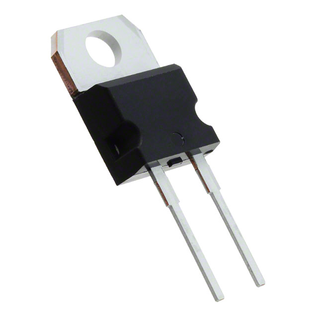
STMicroelectronics STPSC12H065D
- Part No.:
- STPSC12H065D
- Manufacturer:
- STMicroelectronics
- Category:
- Single Diodes
- Package:
- TO-220-2
- Datasheet:
-
 STPSC12H065D.pdf
- Description:
- DIODE SIL CARB 650V 12A TO220AC
- Quantity:
- Payment:

- Shipping:

Inventory:966
Please send an inquiry. Send us your inquiry, and we will respond immediately.
Product details
Overview
STPSC12H065D from STMicroelectronics is a 650 V, 12 A average forward current silicon carbide Schottky diode in TO-220AC package, designed for high-efficiency PFC stages in AC/DC power supplies. It delivers negligible reverse recovery, temperature-independent switching, and 100 A non-repetitive surge capability at 25 °C, enabling robust operation in hard-switching boost converters.
For engineers reviewing the STPSC12H065D datasheet, STPSC12H065D pinout, STPSC12H065D application, or STPSC12H065D equivalent, key selection criteria include its 1.56 V typical forward voltage at 12 A/25 °C, 600 pF junction capacitance at 0 V, 1.4 °C/W max junction-to-case thermal resistance, and suitability for continuous conduction mode (CCM) PFC designs requiring low EMI and high thermal stability.
Technical Context
This SiC Schottky diode replaces conventional silicon fast recovery diodes in critical high-frequency, high-voltage rectification nodes. Its wide bandgap enables a 650 V blocking rating with zero minority-carrier storage, eliminating reverse recovery charge (Qrr ≈ 0) and associated switching losses.
The device operates up to 175 °C junction temperature with stable VF and IR characteristics - VF increases only to 1.98 V (typ.) at 150 °C/12 A, while IR remains ≤500 µA at 150 °C and VR = 640 V - ensuring predictable performance across industrial ambient conditions.
Key Specifications
| Parameter | Value and Actual Design Meaning |
|---|---|
| VRRM | 650 V - supports universal input (85–265 VAC) PFC stages with ≥2× safety margin against line transients |
| IF(AV) | 12 A at Tc = 130 °C - defines continuous conduction capability with standard heatsink mounting |
| VF (typ.) | 1.56 V at IF = 12 A, Tj = 25 °C - sets baseline conduction loss of ~1.35 W in PFC boost diode path |
| IR (max) | 500 µA at VR = 640 V, Tj = 150 °C - ensures minimal leakage-induced power loss and thermal runaway risk |
| Cj | 600 pF at VR = 0 V, 1 MHz - determines high-frequency turn-off dv/dt sensitivity and snubber design requirements |
| Rth(j-c) | 1.4 °C/W max - enables thermal design with ≤10 K rise per watt dissipated under conduction + switching loss |
| IFSM | 100 A, tp = 10 ms sine, Tc = 25 °C - withstands inrush and overload surges without bond-wire fusing |
Pinout & Package
TO-220AC package: single-ended, isolated tab (cathode), through-hole mounting, epoxy body compliant with UL94 V0. Recommended torque: 0.55 N·m.
| Pin/Terminal | Circuit Role | Design Meaning |
|---|---|---|
| Anode | Current entry node | Connected to boost inductor output; must handle full AC line-frequency ripple plus high-frequency switching current |
| Cathode | Current exit node / Heat sink interface | Electrically connected to metal tab; requires insulated mounting when referenced to ground or high-side potential |
| Tab (Cathode) | Thermal & electrical terminal | Serves as primary heat path to heatsink; electrically identical to cathode pin - no separate isolation required |
Key Features
| Feature | Design Value |
|---|---|
| No reverse recovery (Qrr ≈ 0) | Eliminates switching loss spikes and EMI during diode turn-off in PFC boost stage |
| Temperature-stable VF and IR | Enables consistent efficiency and thermal management across -40 to +175 °C operating range |
| High surge robustness (100 A, 10 ms) | Survives cold-start inrush and short-circuit events without degradation |
| Low Cj (600 pF @ 0 V) | Reduces capacitive turn-off current and associated gate drive loading on PFC MOSFET |
| ECOPACK®-compliant packaging | Meets RoHS and halogen-free requirements for industrial and consumer power supply certifications |
Applications
| Server Power Supply PFC Stage | Industrial Motor Drive Input Rectifier |
|---|---|
Use Scenario: 3 kW CCM boost PFC front-end in 1U server PSU operating at 100 kHz switching frequency. IC Role / Device Role / Timing Role: Main boost rectifier diode handling 12 A average forward current with minimal reverse recovery noise. Use Value: Enables >98% PFC efficiency at full load and reduces EMI filter size by eliminating Qrr-related high-frequency harmonics. | Use Scenario: Input rectification for 7.5 kW VFD with active front-end topology and 150 °C ambient requirement. IC Role / Device Role / Timing Role: High-reliability freewheeling and regeneration path diode in three-phase bridge configuration. Use Value: Maintains stable VF and low leakage at 150 °C junction temperature, avoiding thermal runaway under sustained overload. |
| Telecom Rectifier Module | Renewable Energy Inverter DC Link |
Use Scenario: 2.5 kW telecom rectifier with universal input and forced-air cooling. IC Role / Device Role / Timing Role: Output rectifier in LLC-resonant + synchronous rectification hybrid architecture. Use Value: Delivers 1.56 V VF at 25 °C and only 1.98 V at 150 °C, minimizing conduction loss drift over thermal cycle. | Use Scenario: DC link clamping and regeneration path in 10 kW solar string inverter with 600 V bus. IC Role / Device Role / Timing Role: Bidirectional energy-handling diode supporting reactive power flow during grid synchronization. Use Value: Withstands 650 V repetitive blocking and 400 A peak surge (via IFRM = 50 A, δ = 0.1), supporting dynamic grid fault ride-through. |
Equivalent & Alternatives
The following parts are listed as comparable options for similar high-voltage SiC Schottky diode applications.
| Alternative Part | Technical Difference | Application Difference | Selection Advice |
|---|---|---|---|
| C3D10060A (Wolfspeed) | Same 650 V/10 A rating; lower VF (1.45 V typ. @ 10 A); TO-220-2L package with isolated tab | Requires different mechanical layout due to 2-lead vs. 3-lead TO-220AC footprint | Select if lower conduction loss at <10 A and isolated tab mounting are prioritized |
| SS12065 (GeneSiC) | 650 V/12 A; higher VF (1.85 V typ. @ 12 A); same TO-220AC package; Rth(j-c) = 1.6 °C/W | Higher thermal resistance limits power density in compact heatsink designs | Select if second-source qualification is required and 0.3 V higher VF is acceptable for system-level trade-offs |
Compared with C3D10060A and SS12065, STPSC12H065D offers optimal balance of surge robustness (100 A IFSM), thermal performance (1.4 °C/W), and proven PFC-specific characterization - making it preferred for high-reliability, high-power-density CCM boost designs where transient immunity and thermal stability are critical.
Availability
STPSC12H065D is available at Aetrix Electronics and suitable for server power supplies, industrial motor drives, telecom rectifiers, and renewable energy inverters requiring stable component supply and long-term manufacturing continuity.
Supply support for STPSC12H065D includes scheduled delivery planning, volume procurement assistance, BOM continuity management, traceable sourcing, and lifecycle availability coordination for OEM customers, industrial embedded developers, connected-device designers, and electronics production programs.
Manufacturer
STMicroelectronics is a global semiconductor leader headquartered in Geneva, Switzerland, designing and manufacturing microcontrollers, power devices, sensors, and analog ICs for industrial, automotive, and consumer markets.
The STPSC series belongs to ST's silicon carbide power diode product line, engineered specifically for high-efficiency, high-reliability PFC and output rectification in demanding 650 V applications.
FAQ
Is STPSC12H065D suitable for use in discontinuous conduction mode (DCM) PFC?
Yes. Its zero reverse recovery and low junction capacitance make it highly effective in DCM PFC, where rapid turn-on/turn-off transitions dominate. The 600 pF Cj and negligible Qrr reduce switching losses and EMI generation compared to silicon alternatives, especially at high frequencies above 200 kHz.
What is the maximum recommended case temperature for continuous operation?
The datasheet specifies IF(AV) = 12 A at Tc = 130 °C with duty cycle δ = 0.5. For reliable long-term operation, ST recommends limiting case temperature to ≤130 °C under full-load conditions. Exceeding this requires derating current or improving heatsink thermal resistance to maintain Tj ≤175 °C.
Does STPSC12H065D require a gate driver or external control circuitry?
No. As a passive uncontrolled diode, STPSC12H065D conducts when anode voltage exceeds cathode voltage by >VF and blocks when reverse biased. It requires no gate drive, biasing, or control logic - only proper thermal management and PCB layout for high di/dt paths.
Can STPSC12H065D be paralleled for higher current handling?
Paralleling is not recommended without individual current-sharing resistors or matched thermal mounting. VF has a positive temperature coefficient, but manufacturing tolerances and thermal coupling variations can cause imbalance. For >12 A applications, ST recommends selecting a higher-rated part (e.g., STPSC20H065D) instead of paralleling.
STPSC12H065D Specifications
- Product attributes
- Attribute value
- Manufacturer:
- STMicroelectronics
- Series:
- -
- Package/Case:
- TO-220-2
- Packaging:
- Tube
- Product Status:
- Active
- Technology:
- SiC (Silicon Carbide) Schottky
- Voltage - DC Reverse (Vr) (Max):
- 650 V
- Current - Average Rectified (Io):
- 12A
- Voltage - Forward (Vf) (Max) @ If:
- 1.75 V @ 12 A
- Speed:
- Fast Recovery =< 500ns, > 200mA (Io)
- Reverse Recovery Time (trr):
- -
- Current - Reverse Leakage @ Vr:
- 120 µA @ 650 V
- Capacitance @ Vr, F:
- 600pF @ 0V, 1MHz
- Grade:
- -
- Qualification:
- -
- Mounting Type:
- Through Hole
- Supplier Device Package:
- TO-220AC
- Operating Temperature - Junction:
- -40°C ~ 175°C
STPSC12H065D FAQ
1.How can I place an order for STPSC12H065D through Aetrix?
Please submit a Request for Quotation (RFQ) for STPSC12H065D on Aetrix. Our sales agent will provide a competitive quotation and guide you through the order confirmation once you accept the terms.
2.Are the price and stock information for STPSC12H065D reliable?
The price and inventory of STPSC12H065D are updated periodically and may fluctuate due to market conditions. Stock and pricing data are typically refreshed every 24 hours. Quotation validity for STPSC12H065D is usually 5 days.
3.What payment methods are accepted for STPSC12H065D?
We accept Wire Transfer, PayPal, Credit Card, Western Union, MoneyGram, and Escrow for STPSC12H065D transactions.
Note: Certain payment methods may incur a processing fee.
4.How is shipping managed for STPSC12H065D?
STPSC12H065D orders can be shipped via leading logistics carriers, including DHL, UPS, FedEx, TNT, or Registered Mail.
Once your STPSC12H065D order is processed, you will receive an email with the shipment details and tracking number.
Note: Tracking information may take up to 24 hours to appear. Express delivery typically takes 3–5 business days.
5.How can I obtain technical support or documentation for STPSC12H065D?
For technical support, including STPSC12H065D datasheets, pinout diagrams, or application guidance, please contact our engineering support team. They can provide detailed documentation and assistance for your STPSC12H065D requirements.
6.How does Aetrix verify that STPSC12H065D is sourced from the original manufacturer or authorized distributors?
All STPSC12H065D products on Aetrix are procured from qualified distributors and authorized channels. Our dedicated quality assurance team conducts strict verification, including traceability checks and, if necessary, third-party testing. This ensures that STPSC12H065D meets industry standards.
7.What is the process for return or replacement of STPSC12H065D?
All STPSC12H065D units undergo pre-shipment inspection (PSI). If there is an issue with STPSC12H065D, returns or replacements are accepted under the following conditions:
1.Quantity discrepancies, incorrect items, or visible external defects (such as breakage or corrosion), acknowledged by Aetrix.
2.The issue is reported within 90 days of delivery.
3.The STPSC12H065D part is unused and in its original packaging.
Return procedure for STPSC12H065D:
1.Submit a request within 90 days.
2.Obtain a Return Material Authorization (RMA) from Aetrix.
STPSC12H065D Tags
-
1N4448X-TP
Micro Commercial Co
-
1N4148WX-TP
Micro Commercial Co

-
1N4148TR
onsemi
-
MMSD4148T1G
onsemi

-
MMBD914LT3G
onsemi
-
BAS16HT1G
onsemi
-
1N914BWT
onsemi
-
BAS21LT1G
onsemi
-
LL4148
onsemi

-
BAS16LT1G
onsemi
-
MMSD914T1G
onsemi
-
BAV21W-7-F
Diodes Incorporated
Tech Hub

A practical engineering guide to 3.3V and 5V logic compatibility, input thresholds, resistor dividers, translator ICs, MOSFET level shifting, I2C pull-ups, timing limits and power-sequencing risks.

The 74HC595 uses push-pull logic outputs, while the TPIC6B595 uses 50 V open-drain DMOS sinks for higher-power loads. This guide compares timing, current limits, 3.3 V interfacing, load wiring, thermal…

The 74HC595 converts serial data into eight stable parallel outputs. This guide covers pin functions, shift and storage timing, OE and MR behavior, drive-current limits, cascading, voltage compatibilit…

A technical comparison of level-sensitive latches and edge-triggered flip-flops, covering timing windows, setup and hold limits, master–slave operation, time borrowing, race-through, HDL inference and…

A D latch stores one bit while Enable controls when data can pass. This reference covers gate-level operation, truth tables, transparency, setup and hold timing, LE versus OE, common ICs and practical …

An SR latch stores one bit through cross-coupled feedback. This engineering reference covers NOR and NAND implementations, truth tables, forbidden-state recovery, gated operation, switch debouncing, fa…

Latch circuits retain one bit through feedback. This technical reference covers SR and D latches, truth tables, transparency, timing limits, latch-versus-flip-flop behavior, applications and common log…

An engineering guide to LED driver operation, constant-current and constant-voltage outputs, linear and switching topologies, dimming, IC selection, calculations, replacement compatibility, and fault c…

Operational amplifier guide covering op amp basics, feedback, ideal vs real op amps, common configurations, buffer circuits, offset, bias current, gain-bandwidth, slew rate, rail-to-rail limits and sel…

Jumper cables guide covering safe connection order, red and black clamp placement, final ground connection, cable gauge, length, clamp quality, copper vs CCA cables, jump starter comparison and battery…


