
 My Inquiry
 My Account


STMicroelectronics STSPIN32F0A
- Part No.:
- STSPIN32F0A
- Manufacturer:
- STMicroelectronics
- Category:
- Application Specific Microcontrollers
- Package:
- 48-VFQFN Exposed Pad
- Datasheet:
-
 STSPIN32F0A.pdf
- Description:
- IND.& POWER CONV.
- Quantity:
- Payment:

- Shipping:

Inventory:1,013
Please send an inquiry. Send us your inquiry, and we will respond immediately.
Product details
Overview
STSPIN32F0A from STMicroelectronics is a System-in-Package (SiP) BLDC motor controller integrating a 32-bit ARM® Cortex®-M0 MCU (STM32F031C6-7), triple half-bridge gate drivers (600 mA sink/source), 3.3 V DC/DC buck regulator, 12 V LDO, three rail-to-rail op-amps, and programmable overcurrent comparator - designed for sensorless 6-step and FOC control of three-phase BLDC motors in compact power tools and home appliances.
For engineers reviewing the STSPIN32F0A datasheet, STSPIN32F0A pinout, STSPIN32F0A application, or STSPIN32F0A equivalent, key selection criteria include integrated gate driver current capability, UVLO thresholds across VM/VDD/VREG12/VBOOT, 12-bit ADC channel count (9), thermal protection behavior, and compatibility with shunt-based current sensing topologies using internal op-amps and comparator.
Technical Context
The STSPIN32F0A implements a tightly coupled analog-digital SiP architecture where the embedded STM32F031C6-7 MCU (48 MHz, 32 kB Flash, 4 kB SRAM) directly controls gate timing via advanced-control timer TIM1 while receiving real-time current feedback through three dedicated op-amps and a comparator with three selectable OC thresholds (90–545 mV). All power rails - VM (6.7–45 V), VREG12 (12 V), and VDD (3.3 V) - feature independent UVLO with hysteresis (0.2–0.3 V) and thermal shutdown.
Gate drivers incorporate cross-conduction prevention logic, integrated bootstrap diodes (RDS,diode = 120–240 Ω), and propagation delays matched within 20 ns between high- and low-side paths. The DC/DC buck converter delivers up to 70 mA at 3.3 V with 80% efficiency (VM = 8 V), while the 12 V LDO supplies gate drivers with 20–40 mA current limiting and drop voltage ≤400 mV.
Key Specifications
| Parameter | Value and Actual Design Meaning |
|---|---|
| Operating Voltage (VM) | 6.7–45 V - supports wide-input industrial and battery-powered BLDC systems without external pre-regulation. |
| Gate Driver Sink/Source | 600 mA - drives standard N-channel MOSFETs in half-bridge configuration without external boost circuitry. |
| MCU Core | ARM Cortex-M0 @ 48 MHz - executes real-time FOC algorithms with hardware-accelerated PWM timing via TIM1. |
| ADC Resolution & Channels | 12-bit, up to 9 channels - enables simultaneous sampling of phase currents, bus voltage, and temperature for closed-loop control. |
| Overcurrent Threshold | Programmable: 90 / 255 / 505 mV - sets shunt resistor-based trip points for fast (<120 ns) hardware-level fault response. |
| UVLO Hysteresis (VM) | 0.2 V - prevents oscillation during brown-out conditions in variable-load motor applications. |
| Thermal Resistance (RthJA) | 45.6 °C/W - defines maximum power dissipation (≈1.1 W at Tj = 125 °C, TA = 25 °C) on JEDEC 2s2p board. |
Pinout & Package
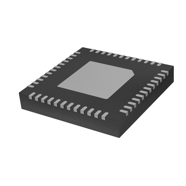
STSPIN32F0A uses VFQFPN48 7 × 7 × 1.0 mm package with 0.5 mm pitch and exposed thermal pad (EPAD) for enhanced thermal performance in motor drive applications.
| Pin/Terminal | Circuit Role | Design Meaning |
|---|---|---|
| VM | Main power supply input | Accepts 6.7–45 V DC; feeds gate drivers, DC/DC buck input, and LDO input; monitored by dedicated UVLO. |
| VREG12 | 12 V linear regulator output | Supplies gate drivers and internal analog blocks; includes overcurrent and thermal protection. |
| VDD | 3.3 V digital supply | Output of integrated DC/DC buck converter; powers MCU core, peripherals, and I/O; UVLO protected. |
| OUTU/OUTV/OUTW | Three-phase motor outputs | High-current half-bridge outputs (HS/LS pairs); support 6-step commutation and FOC with dead-time control. |
| OC_COMP | Overcurrent comparator output | Open-drain fault signal asserted when sensed voltage exceeds programmed threshold; triggers immediate shutdown. |
| PA0–PA15, PB0–PB15, PC13–PC15, PF0–PF7 | GPIO and peripheral signals | 16 GPIOs (5 V tolerant); support SPI/I²C/USART, timers, ADC inputs, SWD debug interface (PA13/PA14). |
Key Features
| Feature | Design Value |
|---|---|
| Integrated 3.3 V DC/DC buck converter | Delivers up to 70 mA with soft-start (2.5–7.5 ms), overcurrent limit (320 mA peak), and power-good flag (VPWR_OK). |
| Dedicated current-sensing analog chain | Three rail-to-rail op-amps + comparator with programmable threshold enable precise shunt-based phase current measurement. |
| Hardware interlock logic | Prevents shoot-through by blocking simultaneous HS/LS activation within same half-bridge - no firmware dependency. |
| Extended temperature range | -40 to +125 °C junction operation - qualified for demanding environments including power tools and vacuum cleaners. |
| Firmware update via serial bootloader | Enables field-programmable motor control algorithms without JTAG debugger; uses UART/SWD interface. |
Applications
| Power Tools | Home Appliance Fans |
|---|---|
|
Use Scenario: Cordless drill/driver with variable speed and torque control under load. IC Role / Device Role / Timing Role: Integrated BLDC controller executing sensorless 6-step commutation with real-time current feedback and thermal management. Use Value: Eliminates need for discrete MCU, gate drivers, regulators, and analog front-end - reduces BOM count by ≥12 components and PCB area by >35%. |
Use Scenario: High-efficiency centrifugal fan in air purifier requiring quiet, variable-speed operation. IC Role / Device Role / Timing Role: Motor controller managing PWM timing, current regulation, and stall detection using internal ADC and comparator. Use Value: Enables smooth 10–100% speed ramping with <5% speed ripple and automatic overcurrent shutdown during blade obstruction. |
| Vacuum Cleaners | Drones & Gimbals |
|
Use Scenario: Brushless suction motor with dynamic load compensation during filter clogging. IC Role / Device Role / Timing Role: Real-time FOC controller using internal op-amps for current sensing and TIM1 for precise vector modulation. Use Value: Maintains constant airflow despite increasing back-pressure by adjusting torque command based on ADC-measured current and voltage. |
Use Scenario: Compact gimbal stabilization system requiring ultra-low latency motor position correction. IC Role / Device Role / Timing Role: Embedded motion controller performing sensorless rotor position estimation and sub-10 µs interrupt-driven PWM updates. Use Value: Achieves <±0.1° angular stability using internal 12-bit ADC sampling at 1 MS/s and hardware-accelerated trigonometric math in Cortex-M0. |
Equivalent & Alternatives
The following parts are listed as comparable options for similar BLDC motor controller applications.
| Alternative Part | Technical Difference | Application Difference | Selection Advice |
|---|---|---|---|
| STSPIN32F0B | Same SiP architecture but with STM32F070CB MCU (128 kB Flash, 16 kB RAM); adds USB interface and higher ADC resolution (12-bit, 16 ch). | Required for USB-enabled firmware updates or multi-motor synchronization via USB-CDC. | Select when field-upgradable connectivity or expanded memory for complex FOC models is needed. |
| DRV8305-Q1 | Automotive-qualified gate driver only (no MCU); requires external processor; supports 100 V VM and 1 A drive strength. | Suitable for automotive HVAC blowers or EPS where AEC-Q100 Grade 1 compliance and higher voltage margin are mandatory. | Choose only if functional safety (ASIL-B) certification and >45 V operation are required - not a drop-in replacement. |
Compared with STSPIN32F0A, STSPIN32F0B offers greater firmware headroom and USB integration but increases cost and footprint; DRV8305-Q1 provides higher voltage/current capability and automotive qualification but shifts all control logic to an external MCU - increasing system complexity and component count.
Availability
STSPIN32F0A is available at Aetrix Electronics and suitable for power tools, home appliance fans, and drone gimbals requiring stable component supply, extended temperature operation (-40 to +125 °C), and integrated motor control functionality.
Supply support for STSPIN32F0A includes scheduled delivery planning, volume procurement assistance, BOM continuity management, traceable sourcing, and lifecycle availability coordination for OEM customers, industrial embedded developers, connected-device designers, and electronics production programs.
Manufacturer
STMicroelectronics is a global semiconductor leader headquartered in Geneva, Switzerland, designing and manufacturing microcontrollers, power ICs, sensors, and analog devices for industrial, automotive, and consumer markets.
The STSPIN family targets highly integrated motor control solutions - combining gate drivers, regulators, analog signal conditioning, and MCUs into single-package SiPs to reduce design cycle time and improve reliability in space-constrained applications.
FAQ
What is the maximum continuous motor phase current supported by STSPIN32F0A?
The STSPIN32F0A does not define maximum motor current directly; it specifies 600 mA gate driver sink/source capability and 1 A latched overcurrent threshold at the comparator input. Actual phase current depends on external MOSFET RDS(on), thermal design, and PCB copper area. With appropriate 20 mΩ shunts and 2 oz copper, sustained 10–15 A RMS per phase is achievable in forced-air-cooled designs.
Does STSPIN32F0A support Hall-effect sensor inputs for commutation?
Yes - the device provides dedicated GPIO pins (e.g., PA8, PA9, PA10) configurable as digital inputs for Hall-effect sensor signals. Its embedded STM32F031C6 MCU supports hardware-timed capture of Hall edges via TIM1 and general-purpose timers, enabling robust 6-step commutation with minimal CPU overhead.
Can the internal op-amps be used for voltage sensing in addition to current sensing?
Yes - the three rail-to-rail op-amps support input common-mode range from -0.1 V to VDD + 0.1 V and have 90 dB CMRR. They are routinely used for bus voltage scaling (e.g., 45 V → 3.3 V via resistive divider), motor back-EMF monitoring, and temperature amplifier interfaces - all without external amplification stages.
Is the STSPIN32F0A pin-compatible with earlier STSPIN32F0 variants?
No - STSPIN32F0A uses VFQFPN48 package with specific pin mapping defined in Table 6 of its datasheet (DocID030766 Rev 2.0). It is not pin-compatible with STSPIN32F0 (VFQFPN32) or STSPIN32F02 (VFQFPN48 with different MCU core and peripheral allocation). PCB layout must be redesigned for migration.
STSPIN32F0A Specifications
- Product attributes
- Attribute value
- Manufacturer:
- STMicroelectronics
- Series:
- STSPIN32F0
- Package/Case:
- 48-VFQFN Exposed Pad
- Packaging:
- Tray
- Product Status:
- Active
- Programmable:
- Not Verified
- Applications:
- BLDC Controller
- Core Processor:
- ARM® Cortex®-M0
- Program Memory Type:
- FLASH (32kB)
- Controller Series:
- STM32F031x6x7
- RAM Size:
- 4K x 8
- Interface:
- I2C, SPI, UART/USART
- Number of I/O:
- 16
- Voltage - Supply:
- 6.7V ~ 45V
- Operating Temperature:
- -40°C ~ 125°C (TJ)
- Grade:
- -
- Qualification:
- -
- Mounting Type:
- Surface Mount
- Supplier Device Package:
- 48-VFQFPN (7x7)
STSPIN32F0A FAQ
1.How can I place an order for STSPIN32F0A through Aetrix?
Please submit a Request for Quotation (RFQ) for STSPIN32F0A on Aetrix. Our sales agent will provide a competitive quotation and guide you through the order confirmation once you accept the terms.
2.Are the price and stock information for STSPIN32F0A reliable?
The price and inventory of STSPIN32F0A are updated periodically and may fluctuate due to market conditions. Stock and pricing data are typically refreshed every 24 hours. Quotation validity for STSPIN32F0A is usually 5 days.
3.What payment methods are accepted for STSPIN32F0A?
We accept Wire Transfer, PayPal, Credit Card, Western Union, MoneyGram, and Escrow for STSPIN32F0A transactions.
Note: Certain payment methods may incur a processing fee.
4.How is shipping managed for STSPIN32F0A?
STSPIN32F0A orders can be shipped via leading logistics carriers, including DHL, UPS, FedEx, TNT, or Registered Mail.
Once your STSPIN32F0A order is processed, you will receive an email with the shipment details and tracking number.
Note: Tracking information may take up to 24 hours to appear. Express delivery typically takes 3–5 business days.
5.How can I obtain technical support or documentation for STSPIN32F0A?
For technical support, including STSPIN32F0A datasheets, pinout diagrams, or application guidance, please contact our engineering support team. They can provide detailed documentation and assistance for your STSPIN32F0A requirements.
6.How does Aetrix verify that STSPIN32F0A is sourced from the original manufacturer or authorized distributors?
All STSPIN32F0A products on Aetrix are procured from qualified distributors and authorized channels. Our dedicated quality assurance team conducts strict verification, including traceability checks and, if necessary, third-party testing. This ensures that STSPIN32F0A meets industry standards.
7.What is the process for return or replacement of STSPIN32F0A?
All STSPIN32F0A units undergo pre-shipment inspection (PSI). If there is an issue with STSPIN32F0A, returns or replacements are accepted under the following conditions:
1.Quantity discrepancies, incorrect items, or visible external defects (such as breakage or corrosion), acknowledged by Aetrix.
2.The issue is reported within 90 days of delivery.
3.The STSPIN32F0A part is unused and in its original packaging.
Return procedure for STSPIN32F0A:
1.Submit a request within 90 days.
2.Obtain a Return Material Authorization (RMA) from Aetrix.
STSPIN32F0A Tags

-
CYPD3175-24LQXQ
Infineon Technologies

-
SLB9672VU20FW1523XTMA1
Infineon Technologies

-
SLB9670VQ20FW785XTMA1
Infineon Technologies
-
SLB9672XU20FW1523XTMA1
Infineon Technologies
-
SLB9673XU20FW2613XTMA1
Infineon Technologies

-
CYPD3125-40LQXIT
Infineon Technologies

-
AT97SC3204-U2A1A-20
Microchip Technology
-
AT97SC3204-U2A1A-10
Microchip Technology
-
SLM9670AQ20FW1311XTMA1
Infineon Technologies
-
SLB9672XU20FW1613XTMA1
Infineon Technologies
-
SLB9672AU20FW1613XTMA1
Infineon Technologies
-
SLB9673AU20FW2613XTMA1
Infineon Technologies
Tech Hub

A practical engineering and sourcing framework covering lifecycle verification, lifetime-buy calculations, replacement qualification, supplier checks and counterfeit-risk controls.

TTL and CMOS logic families differ in thresholds, loading, output drive, power and timing. This engineering guide compares 74HC and 74HCT, calculates noise margins and checks 3.3 V/5 V compatibility.

A practical engineering guide to 3.3V and 5V logic compatibility, input thresholds, resistor dividers, translator ICs, MOSFET level shifting, I2C pull-ups, timing limits and power-sequencing risks.

The 74HC595 uses push-pull logic outputs, while the TPIC6B595 uses 50 V open-drain DMOS sinks for higher-power loads. This guide compares timing, current limits, 3.3 V interfacing, load wiring, thermal…

The 74HC595 converts serial data into eight stable parallel outputs. This guide covers pin functions, shift and storage timing, OE and MR behavior, drive-current limits, cascading, voltage compatibilit…

A technical comparison of level-sensitive latches and edge-triggered flip-flops, covering timing windows, setup and hold limits, master–slave operation, time borrowing, race-through, HDL inference and…

A D latch stores one bit while Enable controls when data can pass. This reference covers gate-level operation, truth tables, transparency, setup and hold timing, LE versus OE, common ICs and practical …

An SR latch stores one bit through cross-coupled feedback. This engineering reference covers NOR and NAND implementations, truth tables, forbidden-state recovery, gated operation, switch debouncing, fa…

Latch circuits retain one bit through feedback. This technical reference covers SR and D latches, truth tables, transparency, timing limits, latch-versus-flip-flop behavior, applications and common log…

An engineering guide to LED driver operation, constant-current and constant-voltage outputs, linear and switching topologies, dimming, IC selection, calculations, replacement compatibility, and fault c…


