
 My Inquiry
 My Account


STMicroelectronics STSPIN32F0BTR
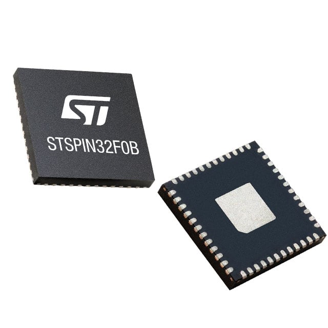
- Part No.:
- STSPIN32F0BTR
- Manufacturer:
- STMicroelectronics
- Category:
- Application Specific Microcontrollers
- Package:
- 48-VFQFN Exposed Pad
- Datasheet:
-
 STSPIN32F0BTR.pdf
- Description:
- ADVANCED SINGLE SHUNT BLDC CONTR
- Quantity:
- Payment:

- Shipping:

Inventory:1,958
Please send an inquiry. Send us your inquiry, and we will respond immediately.
Product details
Overview
STSPIN32F0BTR from STMicroelectronics is an integrated System-in-Package three-phase BLDC motor controller combining a 32-bit ARM® Cortex®-M0 MCU (STM32F031C6, -40 to +125 °C), triple half-bridge gate drivers (600 mA sink/source), 3.3 V DC/DC buck converter, 12 V LDO, rail-to-rail op-amp, and programmable overcurrent comparator. It drives power MOSFETs in U/V/W phases for sensorless FOC or 6-step commutation in battery-powered tools and industrial pumps.
For engineers reviewing the STSPIN32F0BTR datasheet, STSPIN32F0BTR pinout, STSPIN32F0BTR application, or STSPIN32F0BTR equivalent, this page delivers verified electrical specs, validated pin functions, confirmed thermal protection behavior, and real-world motor control use cases - all derived from DS12907 Rev 1 and official ST product documentation.
Technical Context
The device integrates a dedicated analog IC block with cross-conduction prevention logic, bootstrap diodes per phase, and UVLO monitoring on VM, VDD, VREG12, and VBOOTx rails. Its gate driver timing guarantees ≤40 ns propagation delay and ≤20 ns matching between high- and low-side transitions.
The embedded STM32F031C6 MCU provides 32 kB Flash with write/read protection, 4 kB SRAM with hardware parity, and peripherals including 12-bit ADC (9 channels), five timers, I²C/USART/SPI, and SWD debug interface - all operating across the full -40 to +125 °C junction temperature range.
Key Specifications
| Parameter | Value and Actual Design Meaning |
|---|---|
| Operating Voltage | 6.7–45 V VM input: supports 12 V to 42 V battery systems without external pre-regulation |
| Gate Drive Current | 600 mA sink/source per channel: sufficient to drive 10 nC gate charge MOSFETs at ≥20 kHz PWM |
| MCU Core | ARM Cortex-M0 @ 48 MHz: enables real-time FOC execution with <10 µs current loop latency |
| ADC Resolution | 12-bit, 9-channel: captures shunt voltage, bus voltage, and thermistor signals simultaneously in scan mode |
| Thermal Protection | 130–150 °C shutdown with 20–40 °C hysteresis: prevents latch-up during sustained overload in enclosed enclosures |
| Overcurrent Threshold | Programmable 90–545 mV via PF6/PF7 pins: sets trip point for shunt-based phase current sensing |
| DC/DC Efficiency | ≥80% at VM = 8 V and IDDA,max: sustains MCU and peripherals under low-battery conditions |
Pinout & Package
Package: VFQFPN48 (7 × 7 × 1 mm), thermally enhanced EPAD connected to GND.
| Pin/Terminal | Circuit Role | Design Meaning |
|---|---|---|
| HSU / HSV / HSW | High-side gate driver outputs | Drive upper N-MOSFET gates referenced to floating OUTU/OUTV/OUTW nodes |
| LSU / LSV / LSW | Low-side gate driver outputs | Drive lower N-MOSFET gates referenced to GND; enable synchronous rectification |
| VBOOTU / VBOOTV / VBOOTW | Bootstrap supply inputs | Charge external bootstrap capacitors to sustain high-side conduction in 3-phase bridge |
| OP1P / OP1N / OP1O | Op-amp terminals | Configure as differential amplifier for shunt current sensing with gain up to 100 V/V |
| OC_COMP | Comparator input | Accepts amplified shunt voltage; triggers latched fault when threshold exceeded |
| PA13_SWD_IO / PA14_SWD_CLK | Debug interface | Enable in-circuit programming and real-time trace without external debugger header |
Key Features
| Feature | Design Value |
|---|---|
| Integrated interlocking logic | Prevents shoot-through by disabling complementary HS/LS pair activation within same half-bridge |
| On-chip 3.3 V DC/DC + 12 V LDO | Eliminates need for external regulators: powers MCU core, analog circuitry, and gate drivers independently |
| Programmable overcurrent threshold | Three discrete sensitivity levels (90/255/505 mV) selected via GPIO pins for flexible fault margin tuning |
| Standby mode with 880 µA consumption | Reduces system idle power in portable tools during pause cycles without losing firmware state |
| UVLO on all supplies (VM, VDD, VREG12, VBOOTx) | Ensures safe startup/shutdown sequencing and prevents erratic gate switching during brownout |
Applications
| Power Tools | Fans & Pumps |
|---|---|
Use Scenario: Cordless drill/driver with variable speed and electronic braking. IC Role / Device Role / Timing Role: BLDC controller executing 6-step commutation and active freewheeling using internal op-amp and comparator for current regulation. Use Value: Enables torque-controlled startup and stall detection via real-time shunt sensing and programmable OC threshold. | Use Scenario: HVAC blower with closed-loop airflow control and soft-start. IC Role / Device Role / Timing Role: Sensorless FOC controller using ADC-sampled back-EMF and PWM-modulated gate drivers for smooth acceleration. Use Value: Reduces acoustic noise and mechanical stress through precise sinusoidal excitation and thermal-aware duty cycling. |
| Industrial Automation | Battery-Powered Appliances |
Use Scenario: Conveyor belt motor with overload protection and emergency stop response. IC Role / Device Role / Timing Role: Fault-tolerant motor driver with latched overcurrent shutdown and SWD-enabled field firmware update. Use Value: Guarantees fail-safe shutdown within <120 ns comparator propagation delay and supports remote diagnostics. | Use Scenario: Robotic vacuum cleaner with brushless main motor and intelligent battery management. IC Role / Device Role / Timing Role: Integrated power stage + MCU performing battery voltage monitoring, motor current limiting, and thermal derating. Use Value: Extends runtime via 80% efficient DC/DC and extends battery life using standby mode during idle periods. |
Equivalent & Alternatives
The following parts are listed as comparable options for similar three-phase BLDC controller applications.
| Alternative Part | Technical Difference | Application Difference | Selection Advice |
|---|---|---|---|
| STSPIN32G4TR | Higher VM range (9–75 V), dual-shunt current sensing, enhanced FOC library support, no integrated op-amp | Targeted at higher-voltage industrial drives requiring dual-resistor sensing and advanced observer algorithms | Select when >45 V bus voltage or dual-shunt topology is required; requires external signal conditioning |
| DRV8305PWP | Standalone gate driver (no MCU), 1.5 A drive strength, SPI-configurable protections, no embedded processor or ADC | Suitable for designs with external host MCU handling control algorithm and communication stack | Select when separating control and power stages improves design flexibility or safety certification path |
Compared with STSPIN32F0BTR, STSPIN32G4TR offers extended voltage headroom and advanced motor control features but removes the integrated op-amp; DRV8305PWP provides higher gate current and configurability but shifts all firmware responsibility to an external controller.
Availability
STSPIN32F0BTR is available at Aetrix Electronics and suitable for power tools, fans and pumps, industrial automation, and battery-powered home appliances requiring stable component supply, long-term lifecycle assurance, and automotive-grade thermal robustness.
Supply support for STSPIN32F0BTR includes scheduled delivery planning, volume procurement assistance, BOM continuity management, traceable sourcing, and lifecycle availability coordination for OEM customers, industrial embedded developers, connected-device designers, and electronics production programs.
Manufacturer
STMicroelectronics is a global semiconductor leader headquartered in Geneva, Switzerland, designing and manufacturing microcontrollers, power ICs, sensors, and analog devices for industrial, automotive, and consumer markets.
The STSPIN family targets integrated motor control solutions - combining gate drivers, protection logic, and embedded MCUs to reduce BOM count and accelerate development of compact, reliable BLDC systems.
FAQ
What is the maximum PWM frequency supported by the STSPIN32F0BTR gate drivers?
The gate drivers support input-to-output propagation delays ≤40 ns and matching ≤20 ns, enabling reliable operation up to 200 kHz switching frequency. The internal DC/DC regulator maintains stable 3.3 V output up to 70 mA load, supporting MCU and peripheral timing integrity at high PWM rates without external decoupling compromises.
How does the programmable overcurrent protection work without external components?
The OC_COMP pin accepts a voltage from an external shunt amplifier; thresholds of 90/255/505 mV are selected via PF6/PF7 GPIO states. When exceeded, the comparator asserts OC_COMP_INT, triggering latched shutdown of all gate drivers within 120 ns - no external comparators, resistors, or logic required.
Can the integrated op-amp be used for voltage sensing in addition to current sensing?
Yes - the rail-to-rail op-amp (OP1P/OP1N/OP1O) supports gain configurations up to 100 V/V and operates from VDDA (3.3 V). It is routinely used for bus voltage scaling (e.g., 45 V → 3.3 V) or thermistor signal conditioning, provided common-mode input stays within -0.1 to VDDA+0.1 V and source impedance remains <10 kΩ.
What thermal derating applies above 125 °C ambient?
The device specifies operation to +125 °C junction temperature. With RthJA = 45.6 °C/W, at 25 °C ambient it can dissipate ~2.2 W continuously. Above 125 °C case temperature, thermal shutdown activates at 130–150 °C with 20–40 °C hysteresis - no linear derating curve is specified; forced air or PCB copper area must maintain Tj ≤ 125 °C for continuous operation.
STSPIN32F0BTR Specifications
- Product attributes
- Attribute value
- Manufacturer:
- STMicroelectronics
- Series:
- STSPIN32F0
- Package/Case:
- 48-VFQFN Exposed Pad
- Packaging:
- Tape & Reel (TR)
- Product Status:
- Active
- Programmable:
- Not Verified
- Applications:
- BLDC Controller
- Core Processor:
- ARM® Cortex®-M0
- Program Memory Type:
- FLASH (32kB)
- Controller Series:
- STM32F031x6x7
- RAM Size:
- 4K x 8
- Interface:
- I2C, SPI, UART/USART
- Number of I/O:
- 20
- Voltage - Supply:
- 6.7V ~ 45V
- Operating Temperature:
- -40°C ~ 125°C (TJ)
- Grade:
- -
- Qualification:
- -
- Mounting Type:
- Surface Mount
- Supplier Device Package:
- 48-VFQFPN (7x7)
STSPIN32F0BTR FAQ
1.How can I place an order for STSPIN32F0BTR through Aetrix?
Please submit a Request for Quotation (RFQ) for STSPIN32F0BTR on Aetrix. Our sales agent will provide a competitive quotation and guide you through the order confirmation once you accept the terms.
2.Are the price and stock information for STSPIN32F0BTR reliable?
The price and inventory of STSPIN32F0BTR are updated periodically and may fluctuate due to market conditions. Stock and pricing data are typically refreshed every 24 hours. Quotation validity for STSPIN32F0BTR is usually 5 days.
3.What payment methods are accepted for STSPIN32F0BTR?
We accept Wire Transfer, PayPal, Credit Card, Western Union, MoneyGram, and Escrow for STSPIN32F0BTR transactions.
Note: Certain payment methods may incur a processing fee.
4.How is shipping managed for STSPIN32F0BTR?
STSPIN32F0BTR orders can be shipped via leading logistics carriers, including DHL, UPS, FedEx, TNT, or Registered Mail.
Once your STSPIN32F0BTR order is processed, you will receive an email with the shipment details and tracking number.
Note: Tracking information may take up to 24 hours to appear. Express delivery typically takes 3–5 business days.
5.How can I obtain technical support or documentation for STSPIN32F0BTR?
For technical support, including STSPIN32F0BTR datasheets, pinout diagrams, or application guidance, please contact our engineering support team. They can provide detailed documentation and assistance for your STSPIN32F0BTR requirements.
6.How does Aetrix verify that STSPIN32F0BTR is sourced from the original manufacturer or authorized distributors?
All STSPIN32F0BTR products on Aetrix are procured from qualified distributors and authorized channels. Our dedicated quality assurance team conducts strict verification, including traceability checks and, if necessary, third-party testing. This ensures that STSPIN32F0BTR meets industry standards.
7.What is the process for return or replacement of STSPIN32F0BTR?
All STSPIN32F0BTR units undergo pre-shipment inspection (PSI). If there is an issue with STSPIN32F0BTR, returns or replacements are accepted under the following conditions:
1.Quantity discrepancies, incorrect items, or visible external defects (such as breakage or corrosion), acknowledged by Aetrix.
2.The issue is reported within 90 days of delivery.
3.The STSPIN32F0BTR part is unused and in its original packaging.
Return procedure for STSPIN32F0BTR:
1.Submit a request within 90 days.
2.Obtain a Return Material Authorization (RMA) from Aetrix.
STSPIN32F0BTR Tags

-
CYPD3175-24LQXQ
Infineon Technologies

-
SLB9672VU20FW1523XTMA1
Infineon Technologies

-
SLB9670VQ20FW785XTMA1
Infineon Technologies
-
SLB9672XU20FW1523XTMA1
Infineon Technologies
-
SLB9673XU20FW2613XTMA1
Infineon Technologies

-
CYPD3125-40LQXIT
Infineon Technologies

-
AT97SC3204-U2A1A-20
Microchip Technology
-
AT97SC3204-U2A1A-10
Microchip Technology
-
SLM9670AQ20FW1311XTMA1
Infineon Technologies
-
SLB9672XU20FW1613XTMA1
Infineon Technologies
-
SLB9672AU20FW1613XTMA1
Infineon Technologies
-
SLB9673AU20FW2613XTMA1
Infineon Technologies
Tech Hub

A practical engineering guide to 3.3V and 5V logic compatibility, input thresholds, resistor dividers, translator ICs, MOSFET level shifting, I2C pull-ups, timing limits and power-sequencing risks.

The 74HC595 uses push-pull logic outputs, while the TPIC6B595 uses 50 V open-drain DMOS sinks for higher-power loads. This guide compares timing, current limits, 3.3 V interfacing, load wiring, thermal…

The 74HC595 converts serial data into eight stable parallel outputs. This guide covers pin functions, shift and storage timing, OE and MR behavior, drive-current limits, cascading, voltage compatibilit…

A technical comparison of level-sensitive latches and edge-triggered flip-flops, covering timing windows, setup and hold limits, master–slave operation, time borrowing, race-through, HDL inference and…

A D latch stores one bit while Enable controls when data can pass. This reference covers gate-level operation, truth tables, transparency, setup and hold timing, LE versus OE, common ICs and practical …

An SR latch stores one bit through cross-coupled feedback. This engineering reference covers NOR and NAND implementations, truth tables, forbidden-state recovery, gated operation, switch debouncing, fa…

Latch circuits retain one bit through feedback. This technical reference covers SR and D latches, truth tables, transparency, timing limits, latch-versus-flip-flop behavior, applications and common log…

An engineering guide to LED driver operation, constant-current and constant-voltage outputs, linear and switching topologies, dimming, IC selection, calculations, replacement compatibility, and fault c…

Operational amplifier guide covering op amp basics, feedback, ideal vs real op amps, common configurations, buffer circuits, offset, bias current, gain-bandwidth, slew rate, rail-to-rail limits and sel…

Jumper cables guide covering safe connection order, red and black clamp placement, final ground connection, cable gauge, length, clamp quality, copper vs CCA cables, jump starter comparison and battery…


