
 My Inquiry
 My Account


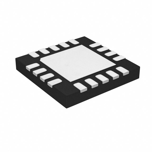
STMicroelectronics TCPP02-M18
- Part No.:
- TCPP02-M18
- Manufacturer:
- STMicroelectronics
- Category:
- Surge Suppression Ics
- Package:
- 18-UFQFN Exposed Pad
- Datasheet:
-
 TCPP02-M18.pdf
- Description:
- USB TYPE-C PORT PROTECTION FOR S
- Quantity:
- Payment:

- Shipping:

Inventory:9,039
Please send an inquiry. Send us your inquiry, and we will respond immediately.
Product details
Overview
TCPP02-M18 from STMicroelectronics is a USB-C source companion IC for MCU-based power delivery systems. It integrates VBUS overcurrent protection with programmable external N-channel MOSFET gate driving, analog current sensing (IANA), CC-line OVP/ESD protection, and I²C-configurable power modes. It enables 100 W SPR compliance in compact chargers and docking stations.
For engineers reviewing the TCPP02-M18 datasheet, TCPP02-M18 pinout, TCPP02-M18 application, or TCPP02-M18 equivalent, key selection criteria include its dual I²C address support for multi-port designs, 42 V/V current-sense gain enabling direct STM32 ADC interfacing, 24 V-tolerant CC pins with IEC 61000-4-2 Level 4 ESD, and integrated VBUS/VCONN discharge paths.
Technical Context
The TCPP02-M18 operates as a hardware protection layer between an MCU's UCPD controller and the USB-C connector. Its functional blocks include a high-side gate driver for external N-MOSFETs, a precision current-sense amplifier (42 V/V gain) with analog output on IANA, and independent OVP circuits on CC1/CC2 (5.75 V threshold, 100 ns response).
It supports three I²C-controlled power states: Hibernate (0 µA VCC_VCONN), Low Power (≤10 µA EN, CC clamped at 5 V), and Normal (2.7 mA VCC_VCONN, full protection and sensing). The FLGn pin provides open-drain fault signaling for OCP, OVP, and OTP events, requiring I²C register reads for root-cause identification.
Key Specifications
| Parameter | Value and Actual Design Meaning |
|---|---|
| VBUS OCP Threshold | 42 mV across external sense resistor - sets trip point for 0.5–6 A range using standard resistor values (e.g., 10 mΩ → 4.2 A) |
| Current Sense Gain | 42 V/V - outputs ~1.95 V at OCP event, compatible with 1.8 V–3.3 V MCU ADC inputs without level-shifting |
| CC Line OVP Threshold | 5.75 V - protects CC1/CC2 against short-to-VBUS during cable unplug, with 100 ns response time |
| I²C Address Options | 0x64 or 0x65 - selected by I2C_ADD pin (GND or 1.8 V/3.3 V), enabling dual-port coordination without address conflict |
| VCONN OCP Limit | 47 mA typical - limits VCONN current to ≤100 mW at 5 V, with soft-start (590 mA for 1 ms) to prevent inrush tripping |
| ESD Robustness | ±8 kV contact / ±15 kV air on CC1c/CC2c - meets IEC 61000-4-2 Level 4 when paired with 100 nF CBIAS capacitor |
| Junction Temp Range | −40 °C to +125 °C - supports operation in wall adapters, car chargers, and industrial docking stations |
Pinout & Package
TCPP02-M18 is housed in a 3.5 mm × 3.5 mm × 0.55 mm QFN-18L package with exposed thermal pad (GND EP). The pinout supports direct integration into space-constrained USB-C source designs with minimal external components.
| Pin/Terminal | Circuit Role | Design Meaning |
|---|---|---|
| EN | Enable control input | Active-high logic input controlling power mode entry; voltage range 1.7–3.6 V defines low-power vs. normal operation |
| GATE / SRC | N-MOSFET gate driver interface | GATE drives external high-side N-FET gate; SRC connects to FET source - enables cost-effective VBUS switching vs. P-MOSFET solutions |
| IANA | Analog current sense output | Provides amplified VBUS current signal (42×) referenced to EN bias - directly interfaces STM32 ADC without external op-amp |
| FLGn | Open-drain fault flag | Active-low indicates OCP/OVP/OTP; requires external pull-up; held low until I²C recovery word (0x68) is written |
| CC1c / CC2c | USB-C connector-side CC pins | 24 V tolerant; integrate OVP clamping and ESD protection - eliminate need for discrete TVS diodes on CC lines |
| I2C_ADD | I²C address LSB selector | Connect to GND (0x64) or 1.8 V/3.3 V (0x65) - enables two TCPP02-M18 devices on same bus in dual-port applications |
Key Features
| Feature | Design Value |
|---|---|
| Externally programmable VBUS OCP | Configured via external sense resistor (e.g., 10 mΩ → 4.2 A trip); avoids fixed-threshold limitations of monolithic PD controllers |
| Integrated VBUS/VCONN discharge paths | On-chip 2.5 kΩ discharge resistors ensure rapid VBUS/VCONN ramp-down (<220 ms), meeting USB-C specification safe-disconnect timing |
| MCU-ADC–ready current sensing | IANA output biased by EN pin delivers 1.7–1.95 V at OCP - eliminates external reference or level-shifter for 1.8 V I/O MCUs |
| Dual I²C address support | Two hardwired addresses (0x64/0x65) simplify firmware for dual-port chargers without I²C multiplexing or GPIO arbitration |
| CC-line short-to-VBUS protection | OVP circuit triggers within 100 ns if CC1/CC2 shorts to VBUS during hot-plug/unplug - prevents damage to UCPD PHY or MCU pins |
Applications
| USB-C Wall Adapter | Multi-Port Desktop Dock |
|---|---|
Use Scenario: Compact 65 W AC/DC adapter with single USB-C port delivering PPS-compatible power. IC Role / Device Role / Timing Role: Companion protector for STM32G0 UCPD controller; manages VBUS switching, current monitoring, and CC-line safety. Use Value: Reduces BOM by replacing ASIC-based PD controllers; enables use of low-RDS(on) N-MOSFETs instead of costly P-MOSFETs. | Use Scenario: 100 W docking station with dual USB-C ports supporting video, data, and power delivery. IC Role / Device Role / Timing Role: Dual TCPP02-M18 instances (I²C_ADD = GND and 3.3 V) provide independent port protection and current sensing. Use Value: Eliminates need for external CC-line ESD diodes and discrete VBUS discharge circuits - saves >3 mm² PCB area per port. |
| Automotive USB-C Charger | USB-C Power Bank |
Use Scenario: 45 W in-car charger with wide-input DC/DC stage and USB-C output. IC Role / Device Role / Timing Role: Handles VBUS OCP under load transients (e.g., sudden device attach), thermal shutdown at 125 °C junction. Use Value: Withstands automotive temperature cycling (−40 °C to +125 °C) and load dumps without derating - no external thermal sensor required. | Use Scenario: Portable 20,000 mAh power bank with bidirectional USB-C PD and PPS charging. IC Role / Device Role / Timing Role: Provides VCONN OCP (47 mA) and discharge for connected accessories; monitors VBUS current during sink/source transitions. Use Value: Integrated VCONN discharge ensures safe accessory disconnect; IANA analog output enables precise battery fuel-gauge integration. |
Equivalent & Alternatives
The following parts are listed as comparable options for similar USB-C source protection applications.
| Alternative Part | Technical Difference | Application Difference | Selection Advice |
|---|---|---|---|
| TPS65987D | Monolithic PD controller with integrated buck-boost, no external MOSFET required; higher system cost and complexity | Targeted at high-end docks with display alt-mode; lacks analog current sense output for MCU ADC | Select when full PD protocol stack offload is needed; avoid when minimizing BOM and leveraging existing MCU UCPD is preferred |
| IP2721 | Standalone PD sink/source controller with internal MOSFETs; no IANA analog output; only one I²C address (0x2C) | Optimized for cost-sensitive single-port adapters; no support for dual-port coordination or direct ADC interfacing | Select for ultra-low-cost consumer adapters; avoid when design requires flexible current monitoring or multi-port synchronization |
Compared with TPS65987D and IP2721, the TCPP02-M18 uniquely balances MCU co-processing efficiency, analog current visibility, and dual-address scalability - making it optimal for mid-tier embedded USB-C source designs where BOM reduction and ADC-integrated telemetry are priorities.
Availability
TCPP02-M18 is available at Aetrix Electronics and suitable for USB-C wall adapters, automotive chargers, desktop docks, and portable power banks requiring stable component supply across industrial temperature ranges and long production lifecycles.
Supply support for TCPP02-M18 includes scheduled delivery planning, volume procurement assistance, BOM continuity management, traceable sourcing, and lifecycle availability coordination for OEM customers, industrial embedded developers, connected-device designers, and electronics production programs.
Manufacturer
STMicroelectronics is a global semiconductor leader headquartered in Geneva, Switzerland, specializing in microcontrollers, power management, and analog/mixed-signal ICs for industrial, automotive, and consumer markets.
The TCPP02-M18 belongs to ST's USB Type-C Protection portfolio, designed specifically to complement STM32 UCPD-enabled MCUs in cost-sensitive, high-volume USB-C source applications - reducing reliance on proprietary PD ASICs.
FAQ
What is the purpose of the CBIAS pin?
The CBIAS pin connects to an external 100 nF capacitor that forms part of the integrated ESD protection circuit for CC1c and CC2c pins. This capacitor works with internal clamping structures to absorb ±8 kV contact and ±15 kV air discharges per IEC 61000-4-2 Level 4, eliminating the need for discrete TVS diodes on the CC lines.
How does the TCPP02-M18 handle VBUS overcurrent recovery?
Upon VBUS OCP detection, the TCPP02-M18 disables the gate driver and holds FLGn low for up to 40 µs while asserting the FLGn_OCP_VBUS flag. Recovery requires writing the specific 8-bit sequence 0x68 (bit pattern 00PM2PM11000) to the I²C command register - after which CC switches re-enable and normal operation resumes.
Can the IANA pin interface directly with a 1.8 V MCU ADC?
Yes. The IANA output is internally biased by the EN pin voltage, producing 1.7–1.95 V at the OCP trip point. This falls within the valid input range of 1.8 V-tolerant ADCs (e.g., STM32G0 series), allowing direct connection without external level-shifting or amplification circuitry.
What is the function of the I2C_ADD pin beyond address selection?
The I2C_ADD pin serves solely to select the LSB of the I²C address (0x64 or 0x65) and has no secondary function. It must be hardwired to GND or a stable 1.8 V/3.3 V rail - floating or dynamically driven states will cause I²C communication failure and unpredictable device behavior.
TCPP02-M18 Specifications
- Product attributes
- Attribute value
- Manufacturer:
- STMicroelectronics
- Package/Case:
- 18-UFQFN Exposed Pad
- Series:
- -
- Packaging:
- Tape & Reel (TR)
- Product Status:
- Active
- Voltage - Clamping:
- 5V
- Technology:
- External Switch
- Number of Circuits:
- 1
- Applications:
- -
- Grade:
- -
- Qualification:
- -
- Mounting Type:
- Surface Mount
- Supplier Device Package:
- 18-QFN (3.5x3.5)
TCPP02-M18 FAQ
1.How can I place an order for TCPP02-M18 through Aetrix?
Please submit a Request for Quotation (RFQ) for TCPP02-M18 on Aetrix. Our sales agent will provide a competitive quotation and guide you through the order confirmation once you accept the terms.
2.Are the price and stock information for TCPP02-M18 reliable?
The price and inventory of TCPP02-M18 are updated periodically and may fluctuate due to market conditions. Stock and pricing data are typically refreshed every 24 hours. Quotation validity for TCPP02-M18 is usually 5 days.
3.What payment methods are accepted for TCPP02-M18?
We accept Wire Transfer, PayPal, Credit Card, Western Union, MoneyGram, and Escrow for TCPP02-M18 transactions.
Note: Certain payment methods may incur a processing fee.
4.How is shipping managed for TCPP02-M18?
TCPP02-M18 orders can be shipped via leading logistics carriers, including DHL, UPS, FedEx, TNT, or Registered Mail.
Once your TCPP02-M18 order is processed, you will receive an email with the shipment details and tracking number.
Note: Tracking information may take up to 24 hours to appear. Express delivery typically takes 3–5 business days.
5.How can I obtain technical support or documentation for TCPP02-M18?
For technical support, including TCPP02-M18 datasheets, pinout diagrams, or application guidance, please contact our engineering support team. They can provide detailed documentation and assistance for your TCPP02-M18 requirements.
6.How does Aetrix verify that TCPP02-M18 is sourced from the original manufacturer or authorized distributors?
All TCPP02-M18 products on Aetrix are procured from qualified distributors and authorized channels. Our dedicated quality assurance team conducts strict verification, including traceability checks and, if necessary, third-party testing. This ensures that TCPP02-M18 meets industry standards.
7.What is the process for return or replacement of TCPP02-M18?
All TCPP02-M18 units undergo pre-shipment inspection (PSI). If there is an issue with TCPP02-M18, returns or replacements are accepted under the following conditions:
1.Quantity discrepancies, incorrect items, or visible external defects (such as breakage or corrosion), acknowledged by Aetrix.
2.The issue is reported within 90 days of delivery.
3.The TCPP02-M18 part is unused and in its original packaging.
Return procedure for TCPP02-M18:
1.Submit a request within 90 days.
2.Obtain a Return Material Authorization (RMA) from Aetrix.
TCPP02-M18 Tags
-
TVS3300DRVR
Texas Instruments

-
TCPP01-M12
STMicroelectronics
-
TPD4S214YFFR
Texas Instruments
-
TPD6S300ARUKR
Texas Instruments
-
TBU-CA085-300-WH
Bourns Inc.
-
TBU-CA065-500-WH
Bourns Inc.
-
TBU-CA040-100-WH
Bourns Inc.
-
TBU-CA085-500-WH
Bourns Inc.
-
TBU-CA085-200-WH
Bourns Inc.
-
NX20P0408UKZ
NXP Semiconductors
-
TBU-CA085-100-WH
Bourns Inc.
-
TBU-CA050-300-WH
Bourns Inc.
Tech Hub

A practical engineering guide to 3.3V and 5V logic compatibility, input thresholds, resistor dividers, translator ICs, MOSFET level shifting, I2C pull-ups, timing limits and power-sequencing risks.

The 74HC595 uses push-pull logic outputs, while the TPIC6B595 uses 50 V open-drain DMOS sinks for higher-power loads. This guide compares timing, current limits, 3.3 V interfacing, load wiring, thermal…

The 74HC595 converts serial data into eight stable parallel outputs. This guide covers pin functions, shift and storage timing, OE and MR behavior, drive-current limits, cascading, voltage compatibilit…

A technical comparison of level-sensitive latches and edge-triggered flip-flops, covering timing windows, setup and hold limits, master–slave operation, time borrowing, race-through, HDL inference and…

A D latch stores one bit while Enable controls when data can pass. This reference covers gate-level operation, truth tables, transparency, setup and hold timing, LE versus OE, common ICs and practical …

An SR latch stores one bit through cross-coupled feedback. This engineering reference covers NOR and NAND implementations, truth tables, forbidden-state recovery, gated operation, switch debouncing, fa…

Latch circuits retain one bit through feedback. This technical reference covers SR and D latches, truth tables, transparency, timing limits, latch-versus-flip-flop behavior, applications and common log…

An engineering guide to LED driver operation, constant-current and constant-voltage outputs, linear and switching topologies, dimming, IC selection, calculations, replacement compatibility, and fault c…

Operational amplifier guide covering op amp basics, feedback, ideal vs real op amps, common configurations, buffer circuits, offset, bias current, gain-bandwidth, slew rate, rail-to-rail limits and sel…

Jumper cables guide covering safe connection order, red and black clamp placement, final ground connection, cable gauge, length, clamp quality, copper vs CCA cables, jump starter comparison and battery…


