
 My Inquiry
 My Account


STMicroelectronics TDA7266S
- Part No.:
- TDA7266S
- Manufacturer:
- STMicroelectronics
- Category:
- Audio Amplifiers
- Package:
- Multiwatt-15 (Vertical, Bent and Staggered Leads)
- Datasheet:
-
 TDA7266S.pdf
- Description:
- IC AMP AB STEREO 5W 15MULTIWATT
- Quantity:
- Payment:

- Shipping:

Inventory:3,433
Please send an inquiry. Send us your inquiry, and we will respond immediately.
Product details
Overview
TDA7266S from STMicroelectronics is a dual-channel Class-AB bridge-tied-load (BTL) audio power amplifier IC designed for TV and portable radio systems. It delivers 5W per channel into 8Ω at 11V supply, operates from 3–18V, features internally fixed 26dB gain, and integrates standby/mute control, thermal shutdown, and short-circuit protection - enabling compact, low-BOM audio output stages in space-constrained consumer electronics.
For engineers reviewing the TDA7266S datasheet, TDA7266S pinout, TDA7266S application, or TDA7266S equivalent, key selection criteria include its wide supply range (3–18V), absence of bootstrap/Boocherot capacitors, dual BTL architecture with independent mute/standby inputs, and thermal protection threshold at 150°C - all critical for robust, low-component-count stereo audio amplification in cost-sensitive embedded audio designs.
Technical Context
The TDA7266S implements a dual BTL output stage with fully integrated biasing and protection logic, eliminating external bootstrap networks and SWR compensation capacitors. Its internal voltage reference (Vref) stabilizes quiescent current across supply variations, while separate ST-BY and MUTE pins enable precise sequencing to suppress turn-on/turn-off pop-noise.
It uses BiCMOS BI20II process technology and features matched closed-loop gain (±0.5dB matching between channels), 46–60dB crosstalk suppression, and 40–56dB supply voltage rejection - confirming suitability for mixed-signal environments where power rail noise and inter-channel isolation are design constraints.
Key Specifications
| Parameter | Value and Actual Design Meaning |
|---|---|
| Output Power | 5W per channel into 8Ω @ 11V, THD = 10% - sufficient for mid-size TV speakers and portable radios without heatsinking. |
| Supply Range | 3–18V DC - supports single-supply operation from Li-ion packs (3.7V) up to 12V/15V legacy TV rails. |
| Closed-Loop Gain | 26dB ±0.5dB - fixed, matched gain eliminates external feedback resistors and ensures consistent channel balance. |
| Mute Attenuation | 60–80dB - deep signal suppression prevents audible click/pop during mute transitions. |
| Thermal Threshold | 150°C junction - triggers automatic shutdown before silicon damage, enabling reliable operation without external thermal sensors. |
| Quiescent Current | 50–60mA total - enables low-power standby mode (100µA ST-BY current) for battery-aware designs. |
| THD @ 1W | 0.05–0.2% - meets fidelity requirements for consumer audio playback at typical listening levels. |
Pinout & Package
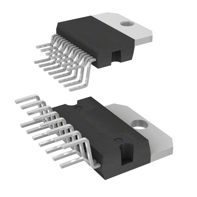
Package: Multiwatt-15 (vertical, 15-pin, thermally enhanced SIP with integral heat slug). Pin 1–15 arranged in single row; mounting hole centered at L3/L4; case temperature monitored via exposed backplate.
| Pin/Terminal | Circuit Role | Design Meaning |
|---|---|---|
| 1, 2, 4 | Vref / NC / NC | Vref provides stable internal reference; pins 2 & 4 are no-connect - must be left unconnected per layout guidelines. |
| 3, 8, 9 | S-GND / PW-GND / PW-GND | Separate signal and power ground returns minimize noise coupling; PW-GND pins handle high-current return paths. |
| 6, 7 | MUTE / ST-BY | Digital control inputs: MUTE active-low (2.3–4.1V threshold), ST-BY active-high (0.8–1.8V threshold) - require precise RC timing for pop-free sequencing. |
| 10, 11 | N.C. / N.C. | No-connect pins - electrically isolated and must remain unconnected to avoid parasitic coupling. |
| 12–15 | OUT2+, OUT2−, OUT1−, OUT1+ | BTL output pairs: OUT1+/− and OUT2+/− deliver differential drive to 8Ω loads - no external output coupling capacitors needed. |
| 13 | VCC | Main supply input (3–18V); requires local 470µF + 100nF decoupling per datasheet layout. |
| 5, 14 | IN1 / IN2 | Differential-capable inputs (25–30kΩ impedance); accept AC-coupled line-level signals via 0.22µF series caps. |
Key Features
| Feature | Design Value |
|---|---|
| No external bootstrap network | Eliminates 2× 10–22µF electrolytic capacitors and associated PCB area - reduces BOM count and layout complexity. |
| Internally fixed gain | 26dB ±0.5dB matching ensures identical channel response without resistor tolerance drift or layout asymmetry. |
| Independent ST-BY/MUTE control | Enables microprocessor-driven sequencing (100–200ms delay) to prevent pop-noise - verified in Fig.1/Fig.2 application circuits. |
| Thermal overload protection | Auto-shutdown at 150°C junction temperature with automatic recovery on cooldown - removes need for external thermal monitoring circuitry. |
| Short-circuit protected outputs | Internally limits peak output current to 1.5A - protects against speaker wire shorts and accidental load misconnection. |
Applications
| TV Audio Output Stage | Portable AM/FM Radio Amplifier |
|---|---|
Use Scenario: Driving 8Ω stereo speakers in 19–24-inch LCD/LED TVs with 12V supply rails and space-limited mainboard layouts. IC Role / Device Role / Timing Role: Dual BTL audio power amplifier delivering 5W × 2 into 8Ω loads; replaces discrete transistor pairs and external gain-setting networks. Use Value: Reduces component count by eliminating bootstrap/Boocherot capacitors and gain resistors - cuts PCB area by >30% vs. discrete solutions. | Use Scenario: Audio output stage in handheld battery-powered radios using 3.7V Li-ion or 6V alkaline supplies. IC Role / Device Role / Timing Role: Low-voltage dual-channel amplifier with 3V minimum operation and <60mA quiescent current in standby mode. Use Value: Enables full audio functionality down to 3V supply - extends usable battery life and avoids brown-out distortion during discharge. |
| Set-Top Box Audio Interface | Compact Home Audio Dock |
Use Scenario: Stereo line-out amplification in HDMI-enabled set-top boxes requiring EMI-robust, low-noise analog audio output. IC Role / Device Role / Timing Role: Differential-input, BTL-output amplifier with 46–60dB crosstalk and 40–56dB SVR - rejects digital switching noise from adjacent SoC domains. Use Value: Maintains clean audio output despite shared 12V rail with noisy video processing ICs - no additional filtering required. | Use Scenario: Embedded stereo amplifier in USB-powered desktop audio docks with 5V USB supply and 8Ω passive speakers. IC Role / Device Role / Timing Role: Wide-supply-range amplifier operating at 5V with 5W/channel output and integrated mute/standby for host-controlled power management. Use Value: Supports USB suspend/resume via ST-BY/MUTE pin sequencing - eliminates pop-noise during host sleep/wake cycles. |
Equivalent & Alternatives
The following parts are listed as comparable options for similar dual BTL audio amplifier applications.
| Alternative Part | Technical Difference | Application Difference | Selection Advice |
|---|---|---|---|
| TDA7265 | Single-ended output (not BTL); 12W into 8Ω @ 16V; requires external bootstrap capacitor. | Lacks integrated mute/standby; higher power but larger external component count. | Select when higher output power is needed and board space allows discrete bootstrap network. |
| TPA2013D1 | Class-D, 3W × 2 into 8Ω @ 5.5V; I²C programmable gain; no ST-BY/MUTE pins - uses EN/SD pins instead. | Higher efficiency (85% vs. ~65%), but requires external LC filter and lacks analog mute threshold control. | Select for battery-powered applications prioritizing efficiency over analog simplicity and pop-noise immunity. |
Compared with TDA7265 and TPA2013D1, the TDA7266S uniquely combines BTL architecture, zero-external-bootstrap operation, and analog-mappable ST-BY/MUTE thresholds - making it optimal for cost-sensitive, low-noise, pop-free analog audio stages where layout simplicity and supply flexibility outweigh raw efficiency or maximum power.
Availability
TDA7266S is available at Aetrix Electronics and suitable for TV audio output stages, portable radio amplifiers, set-top box interfaces, and compact home audio docks requiring stable component supply and long-term production continuity.
Supply support for TDA7266S includes scheduled delivery planning, volume procurement assistance, BOM continuity management, traceable sourcing, and lifecycle availability coordination for OEM customers, industrial embedded developers, connected-device designers, and electronics production programs.
Manufacturer
STMicroelectronics is a global semiconductor leader headquartered in Geneva, Switzerland, specializing in automotive, industrial, and consumer ICs with strong analog and power portfolio heritage.
The TDA7266S belongs to ST's legacy audio power amplifier product line, engineered specifically for cost-optimized, low-BOM-count stereo audio output in mainstream consumer electronics - emphasizing ease of use, thermal robustness, and pop-noise immunity.
FAQ
What is the minimum supply voltage for reliable operation of the TDA7266S?
The TDA7266S operates reliably down to 3V DC supply, delivering usable output power (≥1W per channel) into 8Ω loads at this voltage. Quiescent current remains stable across the full 3–18V range, and internal protection circuits remain functional - confirmed by Figure 8 (Iq vs. Vsupply) and Absolute Maximum Ratings table.
How does the ST-BY pin function, and what voltage level activates it?
The ST-BY pin is active-high with a threshold of 0.8–1.8V (typ. 1.3V). When voltage at pin 7 exceeds this range, the amplifier powers up its bias circuitry; below threshold, it enters ultra-low-current standby (100µA). An external RC network controls ramp rate to prevent pop-noise - detailed in Figure 1 and Application Suggestion section.
Can the TDA7266S drive 4Ω speakers, and what derating applies?
Yes - the TDA7266S can drive 4Ω loads, but output power increases to ~7W per channel at 11V, raising junction temperature. Derating is required: maximum continuous power drops to 3.5W per channel at 4Ω to maintain safe thermal margin below 150°C, per thermal data (Rth j-case = 1.6–2.2°C/W) and SOA curves in datasheet pages 6–7.
Is there a recommended PCB layout for minimizing thermal resistance?
Yes - the Multiwatt-15 package requires direct copper pour connection to the exposed backplate (pins 3, 8, 9 ground planes tied to large thermal pad), with ≥4 thermal vias (0.3mm diameter) under the slug connecting to inner-layer ground planes. Layout Fig. 3b shows optimized copper area and decoupling placement - critical to achieve specified Rth j-case ≤2.2°C/W.
TDA7266S Specifications
- Product attributes
- Attribute value
- Manufacturer:
- STMicroelectronics
- Series:
- -
- Package/Case:
- Multiwatt-15 (Vertical, Bent and Staggered Leads)
- Packaging:
- Tube
- Product Status:
- Obsolete
- Type:
- Class AB
- Output Type:
- 2-Channel (Stereo)
- Max Output Power x Channels @ Load:
- 5W x 2 @ 8Ohm
- Voltage - Supply:
- 3V ~ 18V
- Features:
- Mute, Short-Circuit and Thermal Protection, Standby
- Mounting Type:
- Through Hole
- Operating Temperature:
- 0°C ~ 70°C (TA)
- Grade:
- -
- Qualification:
- -
- Supplier Device Package:
- 15-Multiwatt
TDA7266S FAQ
1.How can I place an order for TDA7266S through Aetrix?
Please submit a Request for Quotation (RFQ) for TDA7266S on Aetrix. Our sales agent will provide a competitive quotation and guide you through the order confirmation once you accept the terms.
2.Are the price and stock information for TDA7266S reliable?
The price and inventory of TDA7266S are updated periodically and may fluctuate due to market conditions. Stock and pricing data are typically refreshed every 24 hours. Quotation validity for TDA7266S is usually 5 days.
3.What payment methods are accepted for TDA7266S?
We accept Wire Transfer, PayPal, Credit Card, Western Union, MoneyGram, and Escrow for TDA7266S transactions.
Note: Certain payment methods may incur a processing fee.
4.How is shipping managed for TDA7266S?
TDA7266S orders can be shipped via leading logistics carriers, including DHL, UPS, FedEx, TNT, or Registered Mail.
Once your TDA7266S order is processed, you will receive an email with the shipment details and tracking number.
Note: Tracking information may take up to 24 hours to appear. Express delivery typically takes 3–5 business days.
5.How can I obtain technical support or documentation for TDA7266S?
For technical support, including TDA7266S datasheets, pinout diagrams, or application guidance, please contact our engineering support team. They can provide detailed documentation and assistance for your TDA7266S requirements.
6.How does Aetrix verify that TDA7266S is sourced from the original manufacturer or authorized distributors?
All TDA7266S products on Aetrix are procured from qualified distributors and authorized channels. Our dedicated quality assurance team conducts strict verification, including traceability checks and, if necessary, third-party testing. This ensures that TDA7266S meets industry standards.
7.What is the process for return or replacement of TDA7266S?
All TDA7266S units undergo pre-shipment inspection (PSI). If there is an issue with TDA7266S, returns or replacements are accepted under the following conditions:
1.Quantity discrepancies, incorrect items, or visible external defects (such as breakage or corrosion), acknowledged by Aetrix.
2.The issue is reported within 90 days of delivery.
3.The TDA7266S part is unused and in its original packaging.
Return procedure for TDA7266S:
1.Submit a request within 90 days.
2.Obtain a Return Material Authorization (RMA) from Aetrix.
TDA7266S Tags
-Exposed-Pad.jpg)
-
TS34119CS RLG
Taiwan Semiconductor Corporation

-
LM386MX-1/NOPB
Texas Instruments

-
TPA711DGNR
Texas Instruments

-
LM386N-4/NOPB
Texas Instruments

-
TS4990IST
STMicroelectronics
-
PAM8302AASCR
Diodes Incorporated
-
TPA6130A2RTJR
Texas Instruments
-
TPA6111A2DGNR
Texas Instruments
-
LM4861MX/NOPB
Texas Instruments
-
LM386M-1/NOPB
Texas Instruments

-
NCS2211DR2G
onsemi
-
IS31AP2005-DLS2-TR
Lumissil Microsystems
Tech Hub

A practical engineering and sourcing framework covering lifecycle verification, lifetime-buy calculations, replacement qualification, supplier checks and counterfeit-risk controls.

TTL and CMOS logic families differ in thresholds, loading, output drive, power and timing. This engineering guide compares 74HC and 74HCT, calculates noise margins and checks 3.3 V/5 V compatibility.

A practical engineering guide to 3.3V and 5V logic compatibility, input thresholds, resistor dividers, translator ICs, MOSFET level shifting, I2C pull-ups, timing limits and power-sequencing risks.

The 74HC595 uses push-pull logic outputs, while the TPIC6B595 uses 50 V open-drain DMOS sinks for higher-power loads. This guide compares timing, current limits, 3.3 V interfacing, load wiring, thermal…

The 74HC595 converts serial data into eight stable parallel outputs. This guide covers pin functions, shift and storage timing, OE and MR behavior, drive-current limits, cascading, voltage compatibilit…

A technical comparison of level-sensitive latches and edge-triggered flip-flops, covering timing windows, setup and hold limits, master–slave operation, time borrowing, race-through, HDL inference and…

A D latch stores one bit while Enable controls when data can pass. This reference covers gate-level operation, truth tables, transparency, setup and hold timing, LE versus OE, common ICs and practical …

An SR latch stores one bit through cross-coupled feedback. This engineering reference covers NOR and NAND implementations, truth tables, forbidden-state recovery, gated operation, switch debouncing, fa…

Latch circuits retain one bit through feedback. This technical reference covers SR and D latches, truth tables, transparency, timing limits, latch-versus-flip-flop behavior, applications and common log…

An engineering guide to LED driver operation, constant-current and constant-voltage outputs, linear and switching topologies, dimming, IC selection, calculations, replacement compatibility, and fault c…


