
 My Inquiry
 My Account


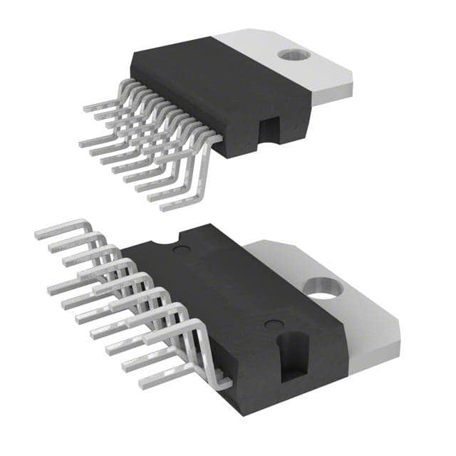
STMicroelectronics TDA7375V
- Part No.:
- TDA7375V
- Manufacturer:
- STMicroelectronics
- Category:
- Audio Amplifiers
- Package:
- Multiwatt-15 (Vertical, Bent and Staggered Leads)
- Datasheet:
-
 TDA7375V.pdf
- Description:
- IC AMP AB DUAL/QUAD 15MULTIWATT
- Quantity:
- Payment:

- Shipping:

Inventory:4,849
Please send an inquiry. Send us your inquiry, and we will respond immediately.
Product details
Overview
TDA7375V from STMicroelectronics is a Class AB quad-channel automotive audio power amplifier capable of dual-bridge (2×40W @4Ω) or quad single-ended (4×12W @2Ω) operation at 14.4V, with internally fixed 26dB BTL gain, CMOS-compatible ST-BY control, and integrated diagnostics for clipping, thermal proximity, and output shorts. It targets car radio mainboard amplification with minimal external components.
For engineers reviewing the TDA7375V datasheet, TDA7375V pinout, TDA7375V application, or TDA7375V equivalent, key selection criteria include bridge vs. SE configuration flexibility, built-in short-circuit diagnostics on Pin 10, rail-to-rail output swing without bootstrap capacitors, and ESD/inductive load robustness per automotive environment requirements.
Technical Context
The TDA7375V implements a fully complementary output stage using ST's proprietary ICV PNP transistors, enabling rail-to-rail swing without bootstrap capacitors and eliminating Boucherot cells. Its loop gain is intrinsically stabilized via local feedback, ensuring oscillation-free operation even at low closed-loop gain.
Diagnostics are consolidated on open-drain Pin 10: current sinking indicates clipping (short pulse), output fault (longer pulse), or thermal shutdown proximity (~10°C before trip). Stand-by activation uses CMOS-level input on Pin 7 with ≤5mA drive capability and mandatory 100nF S-GND decoupling to prevent pop noise.
Key Specifications
| Parameter | Value and Actual Design Meaning |
|---|---|
| Output Power | 2×40W max. @4Ω (bridge), 4×12W @2Ω (SE), 14.4V/1kHz/10% THD - defines speaker drive capability in compact car audio layouts |
| Supply Voltage Range | 8–18V operating, 28V absolute max - supports 12V automotive battery range with load-dump tolerance |
| Voltage Gain | 26dB (bridge), 20dB (SE), internally fixed - eliminates external gain-setting resistors and improves channel matching (±0.5dB) |
| THD+N | 0.03% typ. @1W, 4Ω SE; 0.3% max. @10W, bridge - ensures low audible distortion across full power band |
| Stand-by Attenuation | 80–90dB @1W output - enables silent mute during ignition cycling without relay or external muting circuitry |
| Quiescent Current | 150mA @open load - balances low idle consumption against fast wake-up response in infotainment systems |
| Thermal Resistance | 1.8°C/W (j-case) - mandates heatsink design for ≥23W continuous dissipation in sealed enclosures |
Pinout & Package
MULTIWATT15 (Vertical) package: 15-pin vertical through-hole with integrated heatsink tab (Pin 15), dual ground separation (P-GND Pins 3 & 13, S-GND Pin 1), and dedicated diagnostics output (Pin 10).
| Pin/Terminal | Circuit Role | Design Meaning |
|---|---|---|
| Pin 1 | S-GND | Signal ground reference for inputs, ST-BY, SVR capacitor - must be star-connected near Pin 6, isolated from power ground traces |
| Pins 3, 13 | P-GND | Power ground return for outputs and supply filtering - connects directly to battery negative via low-impedance PCB trace |
| Pin 7 | ST-BY Input | CMOS-compatible enable/disable control; requires series resistor + 100nF S-GND cap to limit current ≤5mA and suppress turn-on pop |
| Pin 10 | DIAGNOSTICS Output | Open-collector fault indicator: sinks current for clipping (short pulse), output short (long pulse), or thermal proximity (~10°C pre-shutdown) |
| Pin 15 | Heatsink Tab | Electrically connected to P-GND; primary thermal path to external heatsink - must be soldered to copper pour or mechanical heatsink |
Key Features
| Feature | Design Value |
|---|---|
| Rail-to-rail output swing | Eliminates need for bootstrap capacitors - reduces BOM count by ≥2 per channel and PCB area by 15% in bridge mode |
| Internally fixed gain | 26dB (BTL), 20dB (SE) - ensures ±0.5dB channel-to-channel matching without external resistor networks |
| Integrated diagnostics | Single-pin (Pin 10) reporting for clipping, GND/VS shorts, soft short at turn-on, and thermal proximity - enables automated assembly test and field failure logging |
| Silent ST-BY transition | Pop-free turn-on/off with internal muting timed by SVR capacitor (Pin 6) - removes need for external relays or soft-start circuits |
| Short-circuit protection | AC/DC short detection to GND, VS, and across load - sustains 50V peak supply surges and survives reversed battery connection |
Applications
| Car Radio Main Amplifier | Aftermarket Head Unit |
|---|---|
Use Scenario: Primary audio amplification in OEM dashboard-mounted car radios with 4-speaker front/rear layout. IC Role / Device Role / Timing Role: Quad-channel Class AB amplifier operating in 4×SE mode driving 4Ω speakers, with diagnostics fed to MCU for real-time fault logging. Use Value: Eliminates external gain-setting resistors and bootstrap caps, reducing component count by 8 parts per channel while maintaining <0.03% THD at 1W. | Use Scenario: Compact 2-DIN aftermarket head unit requiring dual-bridge mode for subwoofer + front channel high-power output. IC Role / Device Role / Timing Role: Dual-bridge amplifier delivering 2×40W @4Ω to subwoofer and front speakers, with ST-BY synchronized to vehicle ignition signal. Use Value: Achieves 40W/channel without external compensation networks, enabling stable operation on cost-optimized 2-layer PCBs with minimal heatsinking. |
| Automotive Infotainment Gateway | Compact Rear-Seat Entertainment |
Use Scenario: Audio subsystem in centralized infotainment gateway supporting multiple display zones and Bluetooth streaming. IC Role / Device Role / Timing Role: Quad-channel SE amplifier with diagnostics routed to system MCU for predictive thermal management and speaker fault isolation. Use Value: Pin 10 diagnostic pulses allow firmware to distinguish clipping (transient) from hard short (persistent), enabling adaptive volume limiting instead of full mute. | Use Scenario: Low-profile rear-seat entertainment module powering two 2Ω speakers from limited board space. IC Role / Device Role / Timing Role: Quad SE amplifier operating at 4×12W @2Ω, leveraging rail-to-rail swing to maximize output voltage swing from 12V supply. Use Value: Delivers 12W/channel into 2Ω loads without current-limiting artifacts, enabling louder playback in confined cabin environments. |
Equivalent & Alternatives
The following parts are listed as comparable options for similar quad-channel automotive audio amplifier applications.
| Alternative Part | Technical Difference | Application Difference | Selection Advice |
|---|---|---|---|
| TDA7377 | Higher 2×48W/4Ω output, but requires external bootstrap capacitors and Boucherot cells - increases BOM count by 6 parts | Targeted at premium head units needing >40W/channel; lacks integrated soft-short detection at turn-on | Select when maximum output power outweighs component count and diagnostics requirements |
| TPA5560QPHPRQ1 | Class D architecture, 2×50W/4Ω, 90% efficiency; no built-in diagnostics pin - requires external comparator circuit for fault detection | Used in thermally constrained modules where heatsink size must be minimized; diagnostics require additional IC and firmware logic | Select when system-level efficiency >85% is mandatory and diagnostic integration can be handled externally |
Compared with TDA7375V, TDA7377 delivers higher peak power but sacrifices integration (no internal gain, no diagnostics), while TPA5560QPHPRQ1 achieves superior efficiency and power density at the cost of added system complexity for fault monitoring and EMI filtering.
Availability
TDA7375V is available at Aetrix Electronics and suitable for automotive infotainment systems, OEM car radio designs, and aftermarket head units requiring stable component supply across extended temperature ranges and long production lifecycles.
Supply support for TDA7375V includes scheduled delivery planning, volume procurement assistance, BOM continuity management, traceable sourcing, and lifecycle availability coordination for OEM customers, industrial embedded developers, connected-device designers, and electronics production programs.
Manufacturer
STMicroelectronics is a global semiconductor leader headquartered in Geneva, Switzerland, specializing in automotive, industrial, and power management ICs with broad manufacturing and qualification capabilities.
The TDA7375V belongs to ST's automotive audio amplifier product line, engineered specifically for cost-sensitive, high-reliability car radio applications demanding integrated diagnostics, minimal external components, and robust short-circuit protection.
FAQ
What is the function of Pin 10 on the TDA7375V?
Pin 10 is an open-collector diagnostics output that sinks current to indicate three distinct conditions: clipping (short-duration pulse), output fault (longer pulse), or thermal shutdown proximity (~10°C before trip). Pulse width differentiation allows microcontroller firmware to isolate fault types without additional hardware.
Can the TDA7375V operate in both bridge and single-ended modes simultaneously?
No - the device must be configured entirely in either dual-bridge (2 channels) or quad single-ended (4 channels) mode per PCB layout. Bridge mode requires shorting IN+ to OUT− for each pair; mixing configurations on one die is not supported due to shared bias and thermal design constraints.
Why does the TDA7375V require separate P-GND and S-GND connections?
Separate power and signal grounds prevent high-current output return paths from modulating input reference voltage. P-GND (Pins 3,13) handles output and supply currents; S-GND (Pin 1) references inputs, ST-BY, and SVR. They must join at a single low-impedance point near the main supply capacitor to avoid ground loops and noise coupling.
What is the minimum recommended heatsink thermal resistance for continuous 2×25W operation?
For continuous 2×25W output at 14.4V, junction temperature must stay below 150°C. With 1.8°C/W j-case resistance and 85°C case limit, total system thermal resistance (heatsink + interface) must be ≤36°C/W. A 25°C/W extruded aluminum heatsink with thermal pad is the practical minimum for enclosed automotive environments.
TDA7375V Specifications
- Product attributes
- Attribute value
- Manufacturer:
- STMicroelectronics
- Series:
- -
- Package/Case:
- Multiwatt-15 (Vertical, Bent and Staggered Leads)
- Packaging:
- Tube
- Product Status:
- Obsolete
- Type:
- Class AB
- Output Type:
- 2-Channel (Stereo) or 4-Channel (Quad)
- Max Output Power x Channels @ Load:
- 40W x 2 @ 4Ohm; 12W x 4 @ 2Ohm
- Voltage - Supply:
- 8V ~ 18V
- Features:
- Depop, Short-Circuit and Thermal Protection, Standby
- Mounting Type:
- Through Hole
- Operating Temperature:
- -40°C ~ 150°C (TJ)
- Grade:
- -
- Qualification:
- -
- Supplier Device Package:
- 15-Multiwatt
TDA7375V FAQ
1.How can I place an order for TDA7375V through Aetrix?
Please submit a Request for Quotation (RFQ) for TDA7375V on Aetrix. Our sales agent will provide a competitive quotation and guide you through the order confirmation once you accept the terms.
2.Are the price and stock information for TDA7375V reliable?
The price and inventory of TDA7375V are updated periodically and may fluctuate due to market conditions. Stock and pricing data are typically refreshed every 24 hours. Quotation validity for TDA7375V is usually 5 days.
3.What payment methods are accepted for TDA7375V?
We accept Wire Transfer, PayPal, Credit Card, Western Union, MoneyGram, and Escrow for TDA7375V transactions.
Note: Certain payment methods may incur a processing fee.
4.How is shipping managed for TDA7375V?
TDA7375V orders can be shipped via leading logistics carriers, including DHL, UPS, FedEx, TNT, or Registered Mail.
Once your TDA7375V order is processed, you will receive an email with the shipment details and tracking number.
Note: Tracking information may take up to 24 hours to appear. Express delivery typically takes 3–5 business days.
5.How can I obtain technical support or documentation for TDA7375V?
For technical support, including TDA7375V datasheets, pinout diagrams, or application guidance, please contact our engineering support team. They can provide detailed documentation and assistance for your TDA7375V requirements.
6.How does Aetrix verify that TDA7375V is sourced from the original manufacturer or authorized distributors?
All TDA7375V products on Aetrix are procured from qualified distributors and authorized channels. Our dedicated quality assurance team conducts strict verification, including traceability checks and, if necessary, third-party testing. This ensures that TDA7375V meets industry standards.
7.What is the process for return or replacement of TDA7375V?
All TDA7375V units undergo pre-shipment inspection (PSI). If there is an issue with TDA7375V, returns or replacements are accepted under the following conditions:
1.Quantity discrepancies, incorrect items, or visible external defects (such as breakage or corrosion), acknowledged by Aetrix.
2.The issue is reported within 90 days of delivery.
3.The TDA7375V part is unused and in its original packaging.
Return procedure for TDA7375V:
1.Submit a request within 90 days.
2.Obtain a Return Material Authorization (RMA) from Aetrix.
TDA7375V Tags
-Exposed-Pad.jpg)
-
TS34119CS RLG
Taiwan Semiconductor Corporation

-
LM386MX-1/NOPB
Texas Instruments

-
TPA711DGNR
Texas Instruments

-
LM386N-4/NOPB
Texas Instruments

-
TS4990IST
STMicroelectronics
-
PAM8302AASCR
Diodes Incorporated
-
TPA6130A2RTJR
Texas Instruments
-
TPA6111A2DGNR
Texas Instruments
-
LM4861MX/NOPB
Texas Instruments
-
LM386M-1/NOPB
Texas Instruments

-
NCS2211DR2G
onsemi
-
IS31AP2005-DLS2-TR
Lumissil Microsystems
Tech Hub

A practical engineering and sourcing framework covering lifecycle verification, lifetime-buy calculations, replacement qualification, supplier checks and counterfeit-risk controls.

TTL and CMOS logic families differ in thresholds, loading, output drive, power and timing. This engineering guide compares 74HC and 74HCT, calculates noise margins and checks 3.3 V/5 V compatibility.

A practical engineering guide to 3.3V and 5V logic compatibility, input thresholds, resistor dividers, translator ICs, MOSFET level shifting, I2C pull-ups, timing limits and power-sequencing risks.

The 74HC595 uses push-pull logic outputs, while the TPIC6B595 uses 50 V open-drain DMOS sinks for higher-power loads. This guide compares timing, current limits, 3.3 V interfacing, load wiring, thermal…

The 74HC595 converts serial data into eight stable parallel outputs. This guide covers pin functions, shift and storage timing, OE and MR behavior, drive-current limits, cascading, voltage compatibilit…

A technical comparison of level-sensitive latches and edge-triggered flip-flops, covering timing windows, setup and hold limits, master–slave operation, time borrowing, race-through, HDL inference and…

A D latch stores one bit while Enable controls when data can pass. This reference covers gate-level operation, truth tables, transparency, setup and hold timing, LE versus OE, common ICs and practical …

An SR latch stores one bit through cross-coupled feedback. This engineering reference covers NOR and NAND implementations, truth tables, forbidden-state recovery, gated operation, switch debouncing, fa…

Latch circuits retain one bit through feedback. This technical reference covers SR and D latches, truth tables, transparency, timing limits, latch-versus-flip-flop behavior, applications and common log…

An engineering guide to LED driver operation, constant-current and constant-voltage outputs, linear and switching topologies, dimming, IC selection, calculations, replacement compatibility, and fault c…


