
 My Inquiry
 My Account


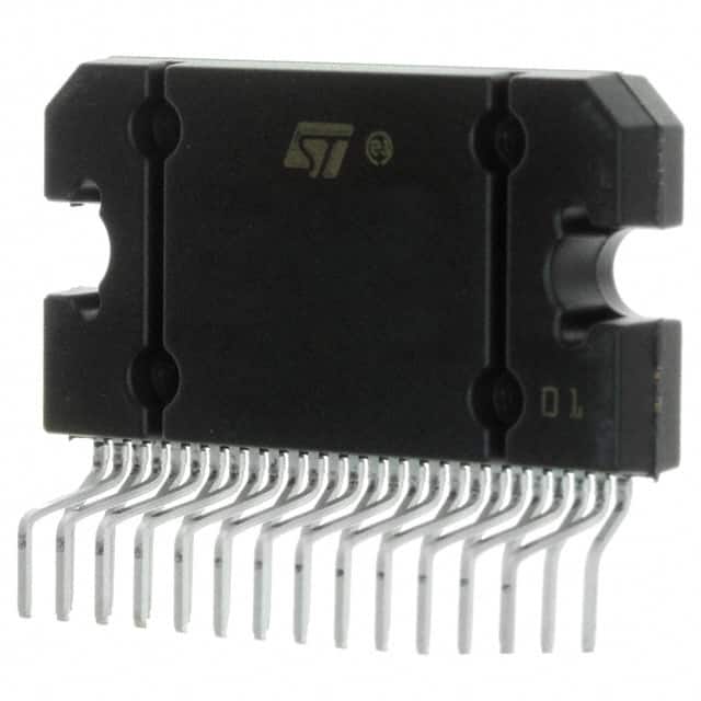
STMicroelectronics TDA7577BLVPDTR
- Part No.:
- TDA7577BLVPDTR
- Manufacturer:
- STMicroelectronics
- Category:
- Audio Amplifiers
- Package:
- PowerSO-36 Exposed Top Pad
- Datasheet:
-
 TDA7577BLVPDTR.pdf
- Description:
- IC AMP AB STEREO 45W POWERSO-36
- Quantity:
- Payment:

- Shipping:

Inventory:1,534
Please send an inquiry. Send us your inquiry, and we will respond immediately.
Product details
Overview
TDA7577BLVPDTR from STMicroelectronics is a dual-bridge Class SB MOSFET audio power amplifier designed for automotive infotainment systems. It delivers 2 × 75 W into 2 Ω, operates down to 6 V for start-stop compatibility, supports full I²C diagnostics with 4 selectable addresses, and features differential inputs, ST-BY/MUTE control, and 1 Ω load capability via parallel output configuration.
For engineers reviewing the TDA7577BLVPDTR datasheet, TDA7577BLVPDTR pinout, TDA7577BLVPDTR application, or TDA7577BLVPDTR equivalent, key selection criteria include low-voltage operation (6–18 V), dual-channel 75 W/2 Ω output, integrated DC/AC fault detection, I²C-addressable diagnostics, and PowerSO-36 thermal performance (Rth j-case = 1 °C/W).
Technical Context
The TDA7577BLVPDTR implements a proprietary high-efficiency Class SB architecture that reduces power dissipation by up to 50% versus conventional Class AB amplifiers. Its DMOS output stage enables stable 1 Ω driving and supports both standard bridge and high-efficiency operating modes with selectable gain (16 dB / 26 dB).
Diagnostics are implemented via dual-path monitoring: turn-on diagnostics verify speaker integrity before enabling output, while permanent diagnostics continuously monitor DC offset, clipping (2%/10% thresholds), short/open load conditions, and thermal status-all communicated over I²C. Legacy mode allows operation without I²C using only ST-BY and MUTE pins.
Key Specifications
| Parameter | Value and Actual Design Meaning |
|---|---|
| Output Power | 2 × 75 W @ 2 Ω, 10% THD; 1 × 150 W @ 1 Ω (parallel mode); enables high-SPL automotive rear-channel or subwoofer drive |
| Supply Voltage Range | 6–18 V DC; supports engine cranking (6 V) and stop-start vehicle architectures without mute/dropout |
| THD+N | 0.04% typ. @ 1–12 W, 1 kHz, 4 Ω (STD mode); ensures low-distortion midrange reproduction in OEM head units |
| I²C Interface | 4 configurable slave addresses; enables daisy-chained diagnostics across multi-amplifier systems without address conflict |
| Thermal Resistance | Rth j-case = 1 °C/W (PowerSO-36); allows 86 W theoretical dissipation at 70 °C case temp-critical for compact under-dash mounting |
| Diagnostic Coverage | Detects short-to-GND (<1.2 V), short-to-VS (>VS−0.9 V), open load (>85 Ω), DC offset (±65 mV), and clipping with user-selectable threshold |
| Gain Options | 26 dB (default) or 16 dB; permits flexible input sensitivity matching to DSP or analog source stages |
Pinout & Package
Package: PowerSO-36 (slug-up), thermally enhanced exposed die pad for direct heatsink mounting; Rth j-case = 1 °C/W.
| Pin/Terminal | Circuit Role | Design Meaning |
|---|---|---|
| VCC | Power supply input | Primary 6–18 V rail; accepts battery transients up to 50 V (50 ms) |
| OUT1A/OUT1B/OUT2A/OUT2B | Dual bridge outputs | Four terminals support independent 2×2 Ω channels or paralleled 1×1 Ω mode via 1Ω pin control |
| ST-BY | Standby enable | Three-level logic: <1.2 V = standby (90 dB attenuation), 2.6–5 V = std bridge, >7 V = Hi-Eff mode |
| MUTE | Mute control | 0–1 V = mute (80 dB attenuation); >2.6 V = active; independent of ST-BY state |
| I²C SDA/SCL | I²C data/clock | Open-drain, 0–6 V tolerant; supports 100 kHz standard-mode bus with ACK polling |
| CLIP | Clipping indicator | Open-drain output asserted low when THD exceeds configured threshold (2% or 10%) |
| 1Ω | Load configuration | 0–1.5 V = dual-channel mode; >2.5 V = 1 Ω parallel mode (enables 150 W single-channel output) |
| SVR | Speaker voltage reference | Analog monitor pin for real-time output voltage sensing during diagnostics |
Key Features
| Feature | Design Value |
|---|---|
| Class SB efficiency | Reduces thermal load by ~50% vs Class AB-enables smaller heatsinks and higher channel density in space-constrained head units |
| Full I²C diagnostics | Reports per-channel fault status (short, open, clipping, DC offset) to host MCU without external ADC or comparators |
| Dual diagnostic modes | Turn-on check validates speaker integrity before enabling output; permanent monitoring detects faults during playback |
| 6 V start-stop operation | Guaranteed functionality at 6 V supply eliminates audio dropout during engine restart in micro-hybrid vehicles |
| Differential inputs | Rejects common-mode noise on long harness runs between head unit and amplifier-improves SNR in noisy automotive environments |
| Configurable clipping threshold | Selectable 2% or 10% THD detection enables trade-off between protection sensitivity and dynamic range preservation |
Applications
| Automotive Head Unit Amplifier | Rear-Seat Entertainment Drive |
|---|---|
|
Use Scenario: Integrated 4-channel amplifier in OEM or aftermarket car stereo head units. IC Role / Device Role / Timing Role: Final-stage dual-bridge audio driver delivering 75 W/channel into 2 Ω speakers with I²C-managed diagnostics. Use Value: Eliminates need for discrete fault-sensing circuitry; 6 V operation prevents mute during engine cranking. |
Use Scenario: Audio power stage for rear-seat screens or wireless headphones in premium vehicles. IC Role / Device Role / Timing Role: High-fidelity 2×28 W driver (14.4 V, 4 Ω, 10% THD) with differential inputs rejecting EMI from display switching. Use Value: Low THD (0.04% typ.) preserves dialog clarity; MUTE/ST-BY sequencing enables silent boot and shutdown. |
| Subwoofer Channel Driver | Start-Stop Compatible Infotainment |
|
Use Scenario: Single-channel 150 W subwoofer output using paralleled bridge configuration. IC Role / Device Role / Timing Role: Configured via 1Ω pin >2.5 V to combine outputs for high-current low-frequency delivery. Use Value: Enables deep bass extension without external current-sharing components; thermal design validated for 86 W dissipation. |
Use Scenario: Primary amplifier in vehicles with automatic engine stop-start systems. IC Role / Device Role / Timing Role: Maintains audio continuity during 6–14 V battery transitions; SVR pin enables real-time rail monitoring. Use Value: Meets OEM requirements for uninterrupted playback during cranking; diagnostic logs aid field failure analysis. |
Equivalent & Alternatives
The following parts are listed as comparable options for similar dual-bridge automotive amplifier applications.
| Alternative Part | Technical Difference | Application Difference | Selection Advice |
|---|---|---|---|
| TDA7560 | Lower max output (2×45 W @ 4 Ω); no I²C interface; legacy analog diagnostics only | Lacks digital fault reporting and addressability; requires external logic for multi-device coordination | Choose for cost-sensitive designs where I²C diagnostics are unnecessary and 45 W/channel suffices |
| MAX9768 | Class D topology; higher efficiency (90%+); 2×50 W @ 4 Ω; I²C-compatible but no 1 Ω mode | No 1 Ω capability or start-stop 6 V operation; limited thermal margin in PowerSSO-36 package | Prefer for ultra-low-power systems needing minimal heatsinking, but not for 1 Ω or cranking-voltage use cases |
Compared with TDA7577BLVPDTR, TDA7560 sacrifices diagnostics and low-voltage robustness for lower BOM cost, while MAX9768 trades 1 Ω drive and 6 V operation for higher peak efficiency-making TDA7577BLVPDTR uniquely suited for demanding OEM start-stop audio systems requiring full digital health monitoring.
Availability
TDA7577BLVPDTR is available at Aetrix Electronics and suitable for automotive infotainment systems, start-stop compatible head units, and high-power rear-channel amplifiers requiring stable component supply, long-term lifecycle assurance, and traceable sourcing.
Supply support for TDA7577BLVPDTR includes scheduled delivery planning, volume procurement assistance, BOM continuity management, traceable sourcing, and lifecycle availability coordination for OEM customers, industrial embedded developers, connected-device designers, and electronics production programs.
Manufacturer
STMicroelectronics is a global semiconductor leader headquartered in Geneva, specializing in automotive, industrial, and power management ICs with broad manufacturing and quality certifications.
The TDA7577BLVPDTR belongs to ST's TDA7xxx automotive audio amplifier family, engineered specifically for OEM-grade car radios requiring robust diagnostics, start-stop compatibility, and high-output thermal efficiency in constrained mechanical envelopes.
FAQ
What is the minimum supply voltage for continuous operation?
The TDA7577BLVPDTR operates continuously from 6 V to 18 V. At 6 V, it delivers up to 6 W total output (2 × 3 W) with 10% THD into 4 Ω, meeting ISO 16750-2 cranking voltage requirements for start-stop vehicles without muting or reset.
How does the 1 Ω parallel mode function electrically?
When the 1Ω pin voltage exceeds 2.5 V, internal switches configure OUT1A/OUT1B and OUT2A/OUT2B as two parallel half-bridges, combining into a single 150 W channel. This mode requires external output inductors and shared load wiring, and is validated for 1 Ω loads at 150 W with 3% THD.
Can the I²C interface be disabled for legacy system integration?
Yes. Pulling the I²C EN pin below 1.5 V disables the I²C peripheral, reverting control to ST-BY and MUTE pins only. All diagnostics remain active but report status via dedicated pins (CLIP, SVR) rather than I²C registers-enabling drop-in replacement in non-I²C designs.
What thermal derating applies above 70 °C case temperature?
With Rth j-case = 1 °C/W, junction temperature rises 1 °C per watt dissipated. At Tcase = 90 °C, maximum safe dissipation drops to 60 W (150 °C − 90 °C) ÷ 1 °C/W. Derated output power must be calculated using thermal curves in Section 3.4 of the datasheet to maintain Tj ≤ 150 °C.
TDA7577BLVPDTR Specifications
- Product attributes
- Attribute value
- Manufacturer:
- STMicroelectronics
- Series:
- -
- Package/Case:
- PowerSO-36 Exposed Top Pad
- Packaging:
- Tape & Reel (TR)
- Product Status:
- Active
- Type:
- Class AB
- Output Type:
- 2-Channel (Stereo)
- Max Output Power x Channels @ Load:
- 45W x 2 @ 4Ohm
- Voltage - Supply:
- 6V ~ 18V
- Features:
- Mute, Short-Circuit Protection, Standby
- Mounting Type:
- Surface Mount
- Operating Temperature:
- -40°C ~ 105°C (TA)
- Grade:
- -
- Qualification:
- -
- Supplier Device Package:
- PowerSO-36
TDA7577BLVPDTR FAQ
1.How can I place an order for TDA7577BLVPDTR through Aetrix?
Please submit a Request for Quotation (RFQ) for TDA7577BLVPDTR on Aetrix. Our sales agent will provide a competitive quotation and guide you through the order confirmation once you accept the terms.
2.Are the price and stock information for TDA7577BLVPDTR reliable?
The price and inventory of TDA7577BLVPDTR are updated periodically and may fluctuate due to market conditions. Stock and pricing data are typically refreshed every 24 hours. Quotation validity for TDA7577BLVPDTR is usually 5 days.
3.What payment methods are accepted for TDA7577BLVPDTR?
We accept Wire Transfer, PayPal, Credit Card, Western Union, MoneyGram, and Escrow for TDA7577BLVPDTR transactions.
Note: Certain payment methods may incur a processing fee.
4.How is shipping managed for TDA7577BLVPDTR?
TDA7577BLVPDTR orders can be shipped via leading logistics carriers, including DHL, UPS, FedEx, TNT, or Registered Mail.
Once your TDA7577BLVPDTR order is processed, you will receive an email with the shipment details and tracking number.
Note: Tracking information may take up to 24 hours to appear. Express delivery typically takes 3–5 business days.
5.How can I obtain technical support or documentation for TDA7577BLVPDTR?
For technical support, including TDA7577BLVPDTR datasheets, pinout diagrams, or application guidance, please contact our engineering support team. They can provide detailed documentation and assistance for your TDA7577BLVPDTR requirements.
6.How does Aetrix verify that TDA7577BLVPDTR is sourced from the original manufacturer or authorized distributors?
All TDA7577BLVPDTR products on Aetrix are procured from qualified distributors and authorized channels. Our dedicated quality assurance team conducts strict verification, including traceability checks and, if necessary, third-party testing. This ensures that TDA7577BLVPDTR meets industry standards.
7.What is the process for return or replacement of TDA7577BLVPDTR?
All TDA7577BLVPDTR units undergo pre-shipment inspection (PSI). If there is an issue with TDA7577BLVPDTR, returns or replacements are accepted under the following conditions:
1.Quantity discrepancies, incorrect items, or visible external defects (such as breakage or corrosion), acknowledged by Aetrix.
2.The issue is reported within 90 days of delivery.
3.The TDA7577BLVPDTR part is unused and in its original packaging.
Return procedure for TDA7577BLVPDTR:
1.Submit a request within 90 days.
2.Obtain a Return Material Authorization (RMA) from Aetrix.
TDA7577BLVPDTR Tags
-Exposed-Pad.jpg)
-
TS34119CS RLG
Taiwan Semiconductor Corporation

-
LM386MX-1/NOPB
Texas Instruments

-
TPA711DGNR
Texas Instruments

-
LM386N-4/NOPB
Texas Instruments

-
TS4990IST
STMicroelectronics
-
PAM8302AASCR
Diodes Incorporated
-
TPA6130A2RTJR
Texas Instruments
-
TPA6111A2DGNR
Texas Instruments
-
LM4861MX/NOPB
Texas Instruments
-
LM386M-1/NOPB
Texas Instruments

-
NCS2211DR2G
onsemi
-
IS31AP2005-DLS2-TR
Lumissil Microsystems
Tech Hub

A practical engineering and sourcing framework covering lifecycle verification, lifetime-buy calculations, replacement qualification, supplier checks and counterfeit-risk controls.

TTL and CMOS logic families differ in thresholds, loading, output drive, power and timing. This engineering guide compares 74HC and 74HCT, calculates noise margins and checks 3.3 V/5 V compatibility.

A practical engineering guide to 3.3V and 5V logic compatibility, input thresholds, resistor dividers, translator ICs, MOSFET level shifting, I2C pull-ups, timing limits and power-sequencing risks.

The 74HC595 uses push-pull logic outputs, while the TPIC6B595 uses 50 V open-drain DMOS sinks for higher-power loads. This guide compares timing, current limits, 3.3 V interfacing, load wiring, thermal…

The 74HC595 converts serial data into eight stable parallel outputs. This guide covers pin functions, shift and storage timing, OE and MR behavior, drive-current limits, cascading, voltage compatibilit…

A technical comparison of level-sensitive latches and edge-triggered flip-flops, covering timing windows, setup and hold limits, master–slave operation, time borrowing, race-through, HDL inference and…

A D latch stores one bit while Enable controls when data can pass. This reference covers gate-level operation, truth tables, transparency, setup and hold timing, LE versus OE, common ICs and practical …

An SR latch stores one bit through cross-coupled feedback. This engineering reference covers NOR and NAND implementations, truth tables, forbidden-state recovery, gated operation, switch debouncing, fa…

Latch circuits retain one bit through feedback. This technical reference covers SR and D latches, truth tables, transparency, timing limits, latch-versus-flip-flop behavior, applications and common log…

An engineering guide to LED driver operation, constant-current and constant-voltage outputs, linear and switching topologies, dimming, IC selection, calculations, replacement compatibility, and fault c…


