
 My Inquiry
 My Account


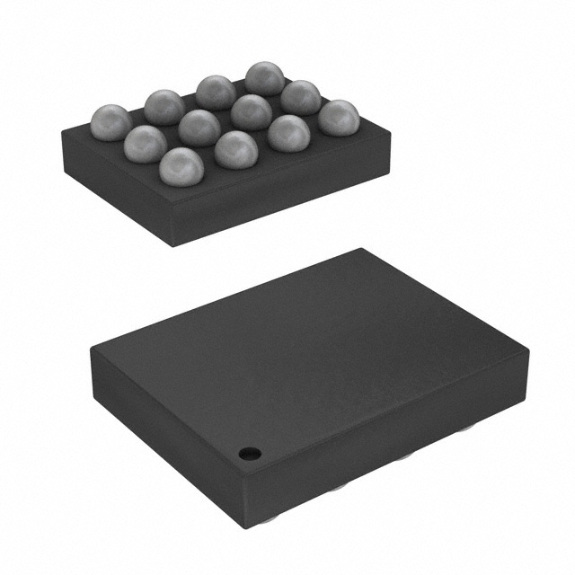
Texas Instruments TPD3S713AQRVCRQ1

- Part No.:
- TPD3S713AQRVCRQ1
- Manufacturer:
- Texas Instruments
- Category:
- Surge Suppression Ics
- Package:
- 20-WFQFN Exposed Pad
- Datasheet:
-
 TPD3S713AQRVCRQ1.pdf
- Description:
- AUTOMOTIVE USB 0.05-A TO 0.6-A A
- Quantity:
- Payment:

- Shipping:

Inventory:2,835
Please send an inquiry. Send us your inquiry, and we will respond immediately.
Product details
Overview
TPD3S713AQRVCRQ1 from Texas Instruments is an AEC-Q100 Grade 1 automotive USB 2.0 interface protection IC with integrated high-bandwidth analog switches (1230 MHz), short-to-battery protection up to 18 V on VBUS/DP_IN/DM_IN, ±8-kV IEC 61000-4-2 contact ESD rating, and adjustable current limit (50–600 mA) for VBUS load switching - deployed in head units and telematics modules.
For engineers reviewing the TPD3S713AQRVCRQ1 datasheet, TPD3S713AQRVCRQ1 pinout, TPD3S713AQRVCRQ1 application, or TPD3S713AQRVCRQ1 equivalent, this page delivers verified electrical specs, validated fault behavior differentiation vs. TPD3S713-Q1, thermal shutdown thresholds (135 °C/155 °C), cable compensation (CS) functionality, and IMON-based current monitoring - all confirmed against TI's SLUSDH1B Rev. B (April 2023) production data sheet.
Technical Context
The TPD3S713AQRVCRQ1 implements dual-path protection: a 73-mΩ high-side MOSFET power switch with UVLO (4.1 V typ.) and overcurrent regulation, plus independent DP/DM analog switches featuring <6.5 Ω on-resistance, <0.15 Ω channel mismatch, and 8.8 pF off-state capacitance - enabling minimal signal degradation during USB 2.0 high-speed (480 Mbps) operation under short-to-battery stress.
Its fault management includes differentiated response logic: unlike TPD3S713-Q1, the TPD3S713AQRVCRQ1 maintains VBUS switch conduction during DP/DM overvoltage events (trip at 3.9 V), while asserting FAULT with 16-ms deglitch; it also supports client-mode configuration via INT1/ILIM_SEL and provides linear IMON output (265 µA typ. at 0.5 A) for system-level power management.
Key Specifications
| Parameter | Value and Actual Design Meaning |
|---|---|
| Operating Temp Range | –40°C to +125°C ambient - qualified per AEC-Q100 Grade 1 for under-hood and infotainment module placement. |
| VBUS Short-Circuit Limit | 50–600 mA adjustable (±13.5% at 200 mA) - set by external ILIM_HI/ILIM_LO resistors; enables precise rail budgeting. |
| Data Switch Bandwidth | 1230 MHz (–3 dB) - preserves USB 2.0 eye integrity across long automotive cables (e.g., 10 cm EVM trace). |
| ESD Protection | ±8-kV contact / ±15-kV air (IEC 61000-4-2) on DP_IN, DM_IN, VBUS - meets automotive EMC requirements without external TVS. |
| Overvoltage Trip Points | DP/DM: 3.9 V (typ.), VBUS: 6.0 V (typ.) - fast response (0.3 µs for VBUS, 5 µs for DP/DM) isolates upstream transceiver during battery faults. |
| Cable Compensation | CS sink current 190–230 µA - dynamically adjusts upstream DC-DC output to maintain stable 5 V at remote USB port under high-current loads. |
| Thermal Shutdown | 135°C (current-limited mode), 155°C (non-current-limited) - hysteresis of 20°C prevents thermal cycling instability. |
Pinout & Package
TPD3S713AQRVCRQ1 uses a 20-pin WQFN package (3.0 mm × 4.0 mm) with exposed thermal pad; RoHS-compliant, moisture sensitivity level 2.
| Pin/Terminal | Circuit Role | Design Meaning |
|---|---|---|
| EN | Enable control input | Logic-level active-high signal to power up/down both data switches and VBUS FET; low = full disable (IIN_OFF ≤ 10 µA). |
| DP_IN / DM_IN | Downstream USB data inputs | Protected I/O pins with 18-V short-to-battery tolerance and ±8-kV IEC ESD; routed through high-BW analog switches. |
| DP_OUT / DM_OUT | Upstream USB data outputs | Low-capacitance (10.9 pF on-state), low-skew (<0.02 ns) paths to host controller; isolation >12 dB at 250 MHz when disabled. |
| VBUS / BUS | Power-switch output | Switched 5-V output (rDS(on) = 73 mΩ typ.) with adjustable current limit and cable compensation feedback (CS pin). |
| IMON | Current monitor output | Sources 265 µA (typ.) at 0.5 A load - linear scaling allows resistor-to-ground conversion to voltage for real-time current sensing. |
| FAULT | Active-low fault indicator | Open-drain output asserted during overtemperature, overcurrent, or overvoltage; 16-ms deglitch for DP/DM OVP, 8-ms for overcurrent. |
| ILIM_HI / ILIM_LO | Current-limit resistor terminals | Analog inputs selecting 50–600 mA limit threshold via external resistors; selection controlled by ILIM_SEL logic pin. |
| INT1 | Mode configuration input | Configures normal mode (INT1 = high) or client mode (INT1 = low + ILIM_SEL = low) - alters fault response behavior per application needs. |
Key Features
| Feature | Design Value |
|---|---|
| Short-to-battery protection | Withstands 18-V DC and hot-plug transients on VBUS, DP_IN, and DM_IN - eliminates need for discrete high-voltage TVS diodes. |
| Differentiated fault handling | TPD3S713AQRVCRQ1 keeps VBUS switch ON during DP/DM overvoltage (vs. full shutdown in TPD3S713-Q1), enabling uninterrupted charging during data-line faults. |
| USB 2.0 signal integrity | 1230-MHz bandwidth and <0.15 Ω DP/DM resistance mismatch preserve 480-Mbps eye diagram even after short-to-battery events. |
| Cable voltage compensation | CS pin sinks 210 µA (typ.) to regulate upstream DC-DC, maintaining stable 5 V at end-of-cable USB ports under 500-mA loads. |
| Integrated current monitoring | IMON pin delivers scalable analog current sense (265 µA/A) - enables dynamic power budgeting and fault diagnostics without external amplifiers. |
Applications
| Automotive Head Unit USB Port | Telematics Control Unit |
|---|---|
Use Scenario: USB 2.0 interface between infotainment head unit and smartphone for CarPlay/Android Auto mirroring and charging. IC Role / Device Role / Timing Role: Protects host-side USB PHY from battery shorts, ESD, and cable-induced voltage drop while preserving high-speed signaling. Use Value: Enables certified USB 2.0 compliance with clean eye diagrams across 10-cm harnesses and eliminates need for separate ESD arrays or load switches. | Use Scenario: USB connection between telematics module and diagnostic tool or firmware update device in vehicle service bay. IC Role / Device Role / Timing Role: Provides fail-safe power/data path with overtemperature lockout (155 °C) and fault reporting (FAULT pin) for service reliability. Use Value: Prevents damage from accidental 12-V battery contact during field servicing and ensures robust communication during firmware updates. |
| Navigation Module Charging Port | Automotive Media Interface Hub |
Use Scenario: Dedicated USB-C or Type-A charging port for rear-seat passengers in center console or overhead console. IC Role / Device Role / Timing Role: Acts as adjustable current-limited load switch (50–600 mA) with cable compensation to sustain 5 V at port despite long wiring. Use Value: Delivers consistent charging performance (no voltage droop) and supports multiple current profiles via resistor programming. | Use Scenario: Central media hub connecting USB storage, wireless dongles, and display interfaces in premium vehicle architectures. IC Role / Device Role / Timing Role: Integrates short-to-battery protection, ESD hardening, and current monitoring into single chip for multi-port scalability. Use Value: Reduces BOM count by replacing discrete protection + switch + monitor solutions; supports client-mode configuration for flexible system integration. |
Equivalent & Alternatives
The following parts are listed as comparable options for similar USB interface protection applications.
| Alternative Part | Technical Difference | Application Difference | Selection Advice |
|---|---|---|---|
| TPD3S713QRVCRQ1 | Shuts down VBUS switch during DP/DM overvoltage; no client-mode support; identical package and pinout. | Less tolerant of concurrent data-line faults during charging; not suitable where continuous VBUS supply is required during OVP. | Select TPD3S713QRVCRQ1 only if full shutdown on DP/DM OVP is acceptable and client-mode functionality is unnecessary. |
| TPD4S012RTER | Single-channel, non-automotive grade; lacks short-to-battery protection, current limiting, and cable compensation; smaller 12-pin WQFN. | Intended for consumer-grade USB ports only; cannot withstand 18-V battery faults or meet AEC-Q100 requirements. | Use TPD4S012RTER only in non-automotive, low-risk USB applications where cost is prioritized over robustness and compliance. |
Compared with TPD3S713QRVCRQ1, the TPD3S713AQRVCRQ1 offers enhanced system uptime via VBUS hold-on during DP/DM overvoltage and client-mode flexibility; versus TPD4S012RTER, it delivers full automotive-grade protection, programmable current limiting, and cable compensation - making it the sole qualified solution for OEM head unit and telematics designs.
Availability
TPD3S713AQRVCRQ1 is available at Aetrix Electronics and suitable for automotive head units, telematics control units, and navigation module charging ports requiring stable component supply, AEC-Q100 compliance, and long-cable USB 2.0 signal integrity.
Supply support for TPD3S713AQRVCRQ1 includes scheduled delivery planning, volume procurement assistance, BOM continuity management, traceable sourcing, and lifecycle availability coordination for OEM customers, industrial embedded developers, connected-device designers, and electronics production programs.
Manufacturer
Texas Instruments is a global semiconductor leader specializing in analog, embedded processing, and connectivity technologies for automotive, industrial, and personal electronics markets.
The TPD3S713x-Q1 product line delivers integrated USB 2.0 protection for automotive infotainment systems - designed to replace discrete protection, switching, and monitoring components while meeting stringent AEC-Q100, IEC 61000-4-2, and ISO 10605 requirements.
FAQ
What is the key functional difference between TPD3S713AQRVCRQ1 and TPD3S713QRVCRQ1?
The TPD3S713AQRVCRQ1 maintains VBUS switch conduction during DP_IN/DM_IN overvoltage events (trip at 3.9 V), whereas TPD3S713QRVCRQ1 shuts down both data switches and VBUS. This allows uninterrupted charging during data-line faults. Both share identical pinout, package, and core protection features - the distinction is documented in TI's SLUSDH1B Rev. B Table 8-1.
How does the cable compensation (CS) feature work in TPD3S713AQRVCRQ1?
The CS pin on TPD3S713AQRVCRQ1 sinks 190–230 µA to regulate the upstream DC-DC converter's feedback node, compensating for IR drop across long USB cables. When load current increases, CS current rises proportionally, instructing the DC-DC to raise its output - ensuring stable 5 V at the remote port. This is confirmed in Section 6.5 and Figure 6-10 of the datasheet.
What are the thermal shutdown thresholds for TPD3S713AQRVCRQ1 and how do they behave?
TPD3S713AQRVCRQ1 has two thermal shutdown thresholds: 135°C during current-limited operation and 155°C otherwise, with 20°C hysteresis. Upon triggering, it immediately disables both power and data switches and asserts FAULT. Recovery requires junction temperature to fall below threshold minus hysteresis - verified in Section 6.5 Electrical Characteristics and Table 8-1.
Can TPD3S713AQRVCRQ1 be used in client-mode configuration, and how is it enabled?
Yes - TPD3S713AQRVCRQ1 supports client-mode via INT1 and ILIM_SEL pins: set INT1 = low and ILIM_SEL = low to activate client-mode, which modifies fault response behavior per application needs. This mode is exclusive to the 'A' variant and is detailed in Section 5 Pin Functions and Table 8-1 of the SLUSDH1B datasheet.
What is the maximum continuous output current capability of TPD3S713AQRVCRQ1's VBUS switch?
The TPD3S713AQRVCRQ1 supports 500-mA maximum continuous output current from its VBUS switch, with rDS(on) = 73 mΩ (typ.) at 25°C. Derating applies above 25°C - e.g., 120 mΩ max at 125°C - and thermal performance is governed by RθJA = 37.9°C/W (WQFN package). These values are specified in Sections 6.5 and 6.4.
TPD3S713AQRVCRQ1 Specifications
- Product attributes
- Attribute value
- Manufacturer:
- Texas Instruments
- Package/Case:
- 20-WFQFN Exposed Pad
- Series:
- -
- Packaging:
- Tape & Reel (TR)
- Product Status:
- Active
- Voltage - Clamping:
- 18V
- Technology:
- Internal Switch
- Number of Circuits:
- 1
- Applications:
- -
- Grade:
- Automotive
- Qualification:
- AEC-Q100
- Mounting Type:
- Surface Mount
- Supplier Device Package:
- 20-WQFN (4x3)
TPD3S713AQRVCRQ1 FAQ
1.How can I place an order for TPD3S713AQRVCRQ1 through Aetrix?
Please submit a Request for Quotation (RFQ) for TPD3S713AQRVCRQ1 on Aetrix. Our sales agent will provide a competitive quotation and guide you through the order confirmation once you accept the terms.
2.Are the price and stock information for TPD3S713AQRVCRQ1 reliable?
The price and inventory of TPD3S713AQRVCRQ1 are updated periodically and may fluctuate due to market conditions. Stock and pricing data are typically refreshed every 24 hours. Quotation validity for TPD3S713AQRVCRQ1 is usually 5 days.
3.What payment methods are accepted for TPD3S713AQRVCRQ1?
We accept Wire Transfer, PayPal, Credit Card, Western Union, MoneyGram, and Escrow for TPD3S713AQRVCRQ1 transactions.
Note: Certain payment methods may incur a processing fee.
4.How is shipping managed for TPD3S713AQRVCRQ1?
TPD3S713AQRVCRQ1 orders can be shipped via leading logistics carriers, including DHL, UPS, FedEx, TNT, or Registered Mail.
Once your TPD3S713AQRVCRQ1 order is processed, you will receive an email with the shipment details and tracking number.
Note: Tracking information may take up to 24 hours to appear. Express delivery typically takes 3–5 business days.
5.How can I obtain technical support or documentation for TPD3S713AQRVCRQ1?
For technical support, including TPD3S713AQRVCRQ1 datasheets, pinout diagrams, or application guidance, please contact our engineering support team. They can provide detailed documentation and assistance for your TPD3S713AQRVCRQ1 requirements.
6.How does Aetrix verify that TPD3S713AQRVCRQ1 is sourced from the original manufacturer or authorized distributors?
All TPD3S713AQRVCRQ1 products on Aetrix are procured from qualified distributors and authorized channels. Our dedicated quality assurance team conducts strict verification, including traceability checks and, if necessary, third-party testing. This ensures that TPD3S713AQRVCRQ1 meets industry standards.
7.What is the process for return or replacement of TPD3S713AQRVCRQ1?
All TPD3S713AQRVCRQ1 units undergo pre-shipment inspection (PSI). If there is an issue with TPD3S713AQRVCRQ1, returns or replacements are accepted under the following conditions:
1.Quantity discrepancies, incorrect items, or visible external defects (such as breakage or corrosion), acknowledged by Aetrix.
2.The issue is reported within 90 days of delivery.
3.The TPD3S713AQRVCRQ1 part is unused and in its original packaging.
Return procedure for TPD3S713AQRVCRQ1:
1.Submit a request within 90 days.
2.Obtain a Return Material Authorization (RMA) from Aetrix.
TPD3S713AQRVCRQ1 Tags
-
TVS3300DRVR
Texas Instruments

-
TCPP01-M12
STMicroelectronics
-
TPD4S214YFFR
Texas Instruments
-
TPD6S300ARUKR
Texas Instruments
-
TBU-CA085-300-WH
Bourns Inc.
-
TBU-CA065-500-WH
Bourns Inc.
-
TBU-CA040-100-WH
Bourns Inc.
-
TBU-CA085-500-WH
Bourns Inc.
-
TBU-CA085-200-WH
Bourns Inc.
-
NX20P0408UKZ
NXP Semiconductors
-
TBU-CA085-100-WH
Bourns Inc.
-
TBU-CA050-300-WH
Bourns Inc.
Tech Hub

A practical engineering guide to 3.3V and 5V logic compatibility, input thresholds, resistor dividers, translator ICs, MOSFET level shifting, I2C pull-ups, timing limits and power-sequencing risks.

The 74HC595 uses push-pull logic outputs, while the TPIC6B595 uses 50 V open-drain DMOS sinks for higher-power loads. This guide compares timing, current limits, 3.3 V interfacing, load wiring, thermal…

The 74HC595 converts serial data into eight stable parallel outputs. This guide covers pin functions, shift and storage timing, OE and MR behavior, drive-current limits, cascading, voltage compatibilit…

A technical comparison of level-sensitive latches and edge-triggered flip-flops, covering timing windows, setup and hold limits, master–slave operation, time borrowing, race-through, HDL inference and…

A D latch stores one bit while Enable controls when data can pass. This reference covers gate-level operation, truth tables, transparency, setup and hold timing, LE versus OE, common ICs and practical …

An SR latch stores one bit through cross-coupled feedback. This engineering reference covers NOR and NAND implementations, truth tables, forbidden-state recovery, gated operation, switch debouncing, fa…

Latch circuits retain one bit through feedback. This technical reference covers SR and D latches, truth tables, transparency, timing limits, latch-versus-flip-flop behavior, applications and common log…

An engineering guide to LED driver operation, constant-current and constant-voltage outputs, linear and switching topologies, dimming, IC selection, calculations, replacement compatibility, and fault c…

Operational amplifier guide covering op amp basics, feedback, ideal vs real op amps, common configurations, buffer circuits, offset, bias current, gain-bandwidth, slew rate, rail-to-rail limits and sel…

Jumper cables guide covering safe connection order, red and black clamp placement, final ground connection, cable gauge, length, clamp quality, copper vs CCA cables, jump starter comparison and battery…


