Send an Inquiry

To receive a quote for your project, please fill in the following information, and we’ll get back to you promptly.

Name*
Company*
Email Address*
Phone/WhatsApp
Part Number*
Quantity*
Message
Submit Inventory List

Please fill in the following information, and we’ll get back to you promptly.

Name*
Company*
Email Address*
Phone/WhatsApp
Upload My List
Message

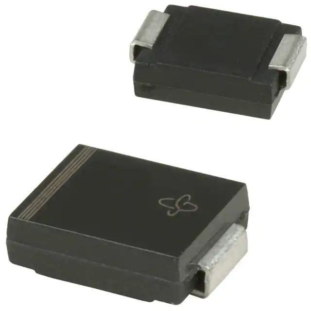
Vishay General Semiconductor - Diodes Division TPSMC39HE3_A/I
Part No.:
TPSMC39HE3_A/I
Manufacturer:
Vishay General Semiconductor - Diodes Division
Category:
TVS Diodes
Package:
DO-214AB, SMC
Datasheet:
AetrixTPSMC39HE3_A/I.pdf
Description:
TVS DIODE 31.6VWM 56.4VC DO214AB
Quantity:
Payment:
Payment
Shipping:
Shipping

Inventory:2,392

Please send an inquiry. Send us your inquiry, and we will respond immediately.

Part Number
Quantity*
Price
Name*
Company
Email*
Comments

Product details

Overview

TPSMC39HE3_A/I from Vishay General Semiconductor is a unidirectional surface-mount transient voltage suppressor (TVS) diode in SMC (DO-214AB) package, rated for 1500 W peak pulse power (10/1000 μs), 39.0 V nominal breakdown voltage (VBR), and 53.9 V maximum clamping voltage (VC) at 27.8 A peak pulse current. It operates from −65 °C to +185 °C and is AEC-Q101 qualified for automotive electronics protection.

For engineers reviewing the TPSMC39HE3_A/I datasheet, TPSMC39HE3_A/I pinout, TPSMC39HE3_A/I application, or TPSMC39HE3_A/I equivalent, key selection criteria include unidirectional polarity, 33.3 V stand-off voltage (VWM), <1.0 μA reverse leakage at VWM, 185 °C junction rating, and RoHS-compliant, halogen-free HE3 suffix construction.

Technical Context

This TVS diode uses passivated anisotropic rectifier technology optimized for high-temperature stability and fast response to transients. Its junction design enables reliable clamping under repetitive surge conditions up to 185 °C junction temperature, with low incremental surge resistance ensuring minimal voltage overshoot during ESD or load-switching events.

The device delivers 1500 W peak pulse power per 10/1000 μs waveform when mounted on 8.0 mm × 8.0 mm copper pads, and meets MSL Level 1 per J-STD-020 with 260 °C reflow peak. It is specifically qualified to AEC-Q101 for automotive-grade reliability in harsh environments.

Key Specifications

Parameter Value and Actual Design Meaning
VBR (min/typ/max) 37.1 / 39.0 / 41.0 V - ensures precise overvoltage triggering above system operating voltage
VWM 33.3 V - maximum continuous reverse working voltage before leakage exceeds 1.0 μA
VC @ IPPM 53.9 V at 27.8 A - clamping voltage limits downstream IC stress during 10/1000 μs surges
PPPM 1500 W - handles high-energy transients from inductive switching or lightning-induced surges
TJ max +185 °C - supports operation in engine bay, powertrain, and under-hood automotive modules
Polarity Unidirectional - protects DC-biased lines such as power rails and sensor supply paths
Package SMC (DO-214AB) - industry-standard surface-mount outline with 0.320" body length and matte tin leads

Pinout & Package

Package: SMC (DO-214AB), molded case meeting UL 94 V-0 flammability rating; terminals are matte tin plated, solderable per J-STD-002 and JESD 22-B102; cathode indicated by color band.

Pin/Terminal Circuit Role Design Meaning
Anode Current entry terminal under forward bias Connected to ground or lower-potential node in unidirectional TVS configuration
Cathode Current exit terminal under forward bias; marked with band Connected to protected line (e.g., 33.3 V rail); clamps to VC when voltage exceeds VBR

Key Features

Feature Design Value
Junction passivation Optimized anisotropic rectifier structure improves long-term reliability under thermal cycling and humidity
AEC-Q101 qualification Validated for automotive applications including powertrain control units and ADAS sensor interfaces
MSL Level 1 Enables single-reflow assembly without moisture sensitivity concerns (peak 260 °C)
Low clamping ratio (VC/VBR) 1.38 - tight clamping margin preserves safe operating area of protected MOSFETs and ICs
High IFSM 200 A - withstands repeated 8.3 ms half-sine surges common in motor drive and relay coil snubbing

Applications

Automotive Power Rail Protection Industrial Sensor Interface Protection

Use Scenario: Protecting 3.3 V or 5 V microcontroller supply lines in engine control modules exposed to load-dump and alternator ripple.

IC Role / Device Role / Timing Role: Unidirectional TVS clamp placed between power input and ground to shunt transient energy before it reaches LDOs or MCU pins.

Use Value: Withstands 185 °C ambient and clamps to ≤53.9 V, preventing latch-up or gate oxide damage in automotive-grade MCUs.

Use Scenario: Safeguarding analog output lines (e.g., 4–20 mA current loops) in industrial pressure transmitters subject to field wiring ESD and inductive kickback.

IC Role / Device Role / Timing Role: TVS placed across signal and return path to limit differential-mode transients before they reach precision DAC or op-amp inputs.

Use Value: 1.0 μA leakage at 33.3 V ensures no measurable error in µA-level current loop accuracy.

Telecom Line Card Surge Suppression Consumer USB Power Delivery Protection

Use Scenario: Front-end protection for PoE-powered Ethernet switches where DC bias (up to 57 V) coexists with fast-rising lightning-induced surges.

IC Role / Device Role / Timing Role: Standoff-rated TVS (VWM = 33.3 V) used in series with higher-voltage devices to handle intermediate clamping tiers.

Use Value: 1500 W pulse rating and 27.8 A IPPM enable coordination with upstream GDTs or MOVs in multi-stage telecom protectors.

Use Scenario: Input-side transient suppression on USB-C PD 20 V power rails in portable monitors and docking stations.

IC Role / Device Role / Timing Role: Unidirectional TVS connected between VBUS and GND to absorb plug/unplug ESD and hot-swap overshoot.

Use Value: Fast response time and 53.9 V clamping prevent overvoltage damage to USB PD controllers rated for 28 V absolute maximum.

Equivalent & Alternatives

The following parts are listed as comparable options for similar transient suppression applications.

Alternative Part Technical Difference Application Difference Selection Advice
SMAJ36A Lower PPPM (400 W), smaller SMA package, VBR = 36–39.9 V, VC = 58.1 V at 6.9 A Suitable for lower-energy consumer applications; not AEC-Q101 qualified Select SMAJ36A only for cost-sensitive, non-automotive designs with <400 W surge requirements.
TPSMC36AHE3_A/I Identical package and qualification; VBR = 34.2–37.8 V, VWM = 30.8 V, VC = 49.9 V at 30.1 A Better suited for 24 V nominal systems requiring tighter clamping margin Choose TPSMC36AHE3_A/I when protecting 24 V rails where 30.8 V VWM provides larger noise margin vs. 33.3 V of TPSMC39HE3_A/I.

Compared with SMAJ36A and TPSMC36AHE3_A/I, the TPSMC39HE3_A/I offers higher energy handling (1500 W vs. 400 W or same-family 1500 W), tighter clamping (53.9 V vs. 58.1 V or 49.9 V), and a 33.3 V standoff ideal for 36 V nominal systems-making it optimal for robust 12/24/36 V automotive and industrial power rail protection.

Availability

TPSMC39HE3_A/I is available at Aetrix Electronics and suitable for automotive power distribution modules, industrial sensor signal conditioning circuits, and telecom line card surge protection requiring stable component supply, AEC-Q101 compliance, and high-temperature operational continuity.

Supply support for TPSMC39HE3_A/I includes scheduled delivery planning, volume procurement assistance, BOM continuity management, traceable sourcing, and lifecycle availability coordination for OEM customers, industrial embedded developers, connected-device designers, and electronics production programs.

Manufacturer

Vishay General Semiconductor is a global leader in discrete semiconductors, specializing in diodes, rectifiers, TVS devices, and optoelectronics with emphasis on reliability, high-temperature performance, and automotive qualification.

The TPSMC series is designed for high-energy transient suppression in demanding environments-specifically targeting automotive, industrial, and telecom applications where 1500 W surge capability, 185 °C operation, and AEC-Q101 validation are mandatory.

FAQ

What is the maximum clamping voltage of the TPSMC39HE3_A/I at its rated peak pulse current?

The TPSMC39HE3_A/I has a maximum clamping voltage (VC) of 53.9 V at its rated peak pulse current (IPPM) of 27.8 A, measured using a 10/1000 μs waveform. This value defines the upper voltage limit imposed on protected circuitry during worst-case surge events and is critical for ensuring compatibility with downstream components' absolute maximum ratings. The TPSMC39HE3_A/I maintains this clamping performance across its full operating temperature range.

Is the TPSMC39HE3_A/I suitable for automotive applications?

Yes, the TPSMC39HE3_A/I is AEC-Q101 qualified and rated for junction temperatures up to +185 °C, making it suitable for under-hood and powertrain applications. Its HE3 suffix confirms RoHS compliance, halogen-free construction, and qualification to automotive reliability standards. The TPSMC39HE3_A/I is commonly deployed in engine control units, battery management systems, and ADAS camera modules where sustained high-temperature operation and transient immunity are required.

What does the "HE3" suffix mean in TPSMC39HE3_A/I?

The "HE3" suffix in TPSMC39HE3_A/I indicates RoHS-compliant, halogen-free construction and AEC-Q101 qualification. It also specifies that the device meets JESD 201 Class 2 whisker resistance and is supplied in 13" diameter plastic tape and reel (package code "I"). The "A" denotes the revision level, and "/I" confirms the delivery format-distinct from "/H" (7" reel). This suffix directly identifies the TPSMC39HE3_A/I as an automotive-grade, environmentally compliant variant.

How does the TPSMC39HE3_A/I compare to bidirectional TVS diodes?

The TPSMC39HE3_A/I is unidirectional and intended for DC-biased lines such as power rails and sensor supplies, where reverse polarity is not expected. Unlike bidirectional TVS diodes-which clamp both positive and negative transients-it provides lower leakage (<1.0 μA at 33.3 V) and tighter clamping in the forward direction. For AC-coupled or floating signal lines, a bidirectional part would be required; the TPSMC39HE3_A/I is not suitable for those use cases.

What PCB pad layout is recommended for optimal thermal and surge performance of the TPSMC39HE3_A/I?

Vishay specifies mounting the TPSMC39HE3_A/I on 0.31" × 0.31" (8.0 mm × 8.0 mm) copper pads at each terminal to achieve its rated 1500 W peak pulse power. The SMC (DO-214AB) package requires adequate copper area for heat dissipation during surge events and to maintain junction temperature within limits. Pad dimensions must follow the outline drawing on page 4 of document 88407, with minimum 0.126" anode/cathode pad width and 0.185" maximum center-to-center spacing. Proper layout ensures the TPSMC39HE3_A/I delivers full specified performance.

TPSMC39HE3_A/I Specifications

Product attributes
Attribute value
Manufacturer:
Vishay General Semiconductor - Diodes Division
Package/Case:
DO-214AB, SMC
Series:
PAR®
Packaging:
Tape & Reel (TR)
Product Status:
Obsolete
Type:
Zener
Unidirectional Channels:
1
Bidirectional Channels:
-
Voltage - Reverse Standoff (Typ):
31.6V
Voltage - Breakdown (Min):
35.1V
Voltage - Clamping (Max) @ Ipp:
56.4V
Current - Peak Pulse (10/1000µs):
26.6A
Power - Peak Pulse:
1500W (1.5kW)
Power Line Protection:
No
Applications:
-
Capacitance @ Frequency:
-
Operating Temperature:
-65°C ~ 185°C (TJ)
Grade:
Automotive
Qualification:
AEC-Q101
Mounting Type:
Surface Mount
Supplier Device Package:
DO-214AB (SMCJ)

TPSMC39HE3_A/I FAQ

1.How can I place an order for TPSMC39HE3_A/I through Aetrix?

Please submit a Request for Quotation (RFQ) for TPSMC39HE3_A/I on Aetrix. Our sales agent will provide a competitive quotation and guide you through the order confirmation once you accept the terms.

2.Are the price and stock information for TPSMC39HE3_A/I reliable?

The price and inventory of TPSMC39HE3_A/I are updated periodically and may fluctuate due to market conditions. Stock and pricing data are typically refreshed every 24 hours. Quotation validity for TPSMC39HE3_A/I is usually 5 days.

3.What payment methods are accepted for TPSMC39HE3_A/I?

We accept Wire Transfer, PayPal, Credit Card, Western Union, MoneyGram, and Escrow for TPSMC39HE3_A/I transactions.

Note: Certain payment methods may incur a processing fee.

4.How is shipping managed for TPSMC39HE3_A/I?

TPSMC39HE3_A/I orders can be shipped via leading logistics carriers, including DHL, UPS, FedEx, TNT, or Registered Mail.

Once your TPSMC39HE3_A/I order is processed, you will receive an email with the shipment details and tracking number.

Note: Tracking information may take up to 24 hours to appear. Express delivery typically takes 3–5 business days.

5.How can I obtain technical support or documentation for TPSMC39HE3_A/I?

For technical support, including TPSMC39HE3_A/I datasheets, pinout diagrams, or application guidance, please contact our engineering support team. They can provide detailed documentation and assistance for your TPSMC39HE3_A/I requirements.

6.How does Aetrix verify that TPSMC39HE3_A/I is sourced from the original manufacturer or authorized distributors?

All TPSMC39HE3_A/I products on Aetrix are procured from qualified distributors and authorized channels. Our dedicated quality assurance team conducts strict verification, including traceability checks and, if necessary, third-party testing. This ensures that TPSMC39HE3_A/I meets industry standards.

7.What is the process for return or replacement of TPSMC39HE3_A/I?

All TPSMC39HE3_A/I units undergo pre-shipment inspection (PSI). If there is an issue with TPSMC39HE3_A/I, returns or replacements are accepted under the following conditions:

1.Quantity discrepancies, incorrect items, or visible external defects (such as breakage or corrosion), acknowledged by Aetrix.

2.The issue is reported within 90 days of delivery.

3.The TPSMC39HE3_A/I part is unused and in its original packaging.

Return procedure for TPSMC39HE3_A/I:

1.Submit a request within 90 days.

2.Obtain a Return Material Authorization (RMA) from Aetrix.

TPSMC39HE3_A/I Tags

  • TPSMC39HE3_A/I
  • TPSMC39HE3_A/I PDF
  • TPSMC39HE3_A/I Datasheet
  • TPSMC39HE3_A/I Specifications
  • TPSMC39HE3_A/I Images
  • Vishay General Semiconductor - Diodes Division
  • Vishay General Semiconductor - Diodes Division TPSMC39HE3_A/I
  • Buy TPSMC39HE3_A/I
  • TPSMC39HE3_A/I Price
  • TPSMC39HE3_A/I Distributor
  • TPSMC39HE3_A/I Supplier
  • TPSMC39HE3_A/I Wholesale
Related Products
ESD9B5.0ST5G
ESD9B5.0ST5G

onsemi

DESD3V3E1BL-7B
DESD3V3E1BL-7B

Diodes Incorporated

ESD5Z3.3T1G
ESD5Z3.3T1G

onsemi

D5V0H1B2LP-7B
D5V0H1B2LP-7B

Diodes Incorporated

D5V0P1B2LP-7B
D5V0P1B2LP-7B

Diodes Incorporated

DESD5V0U1BA-7
DESD5V0U1BA-7

Diodes Incorporated

ESD5Z5.0T1G
ESD5Z5.0T1G

onsemi

DESD5V0U1BB-7
DESD5V0U1BB-7

Diodes Incorporated

D12V0L1B2LP-7B
D12V0L1B2LP-7B

Diodes Incorporated

PESD2V0Y1BSFYL
PESD2V0Y1BSFYL

Nexperia USA Inc.

DF2S5M4CT,L3F
DF2S5M4CT,L3F

Toshiba Semiconductor and Storage

D5V0L1B2WS-7
D5V0L1B2WS-7

Diodes Incorporated

Tech Hub
Search

Search

PRODUCT

PRODUCT

PHONE

PHONE

USER

USER