
 My Inquiry
 My Account


STMicroelectronics TS4902IDT

- Part No.:
- TS4902IDT
- Manufacturer:
- STMicroelectronics
- Category:
- Audio Amplifiers
- Package:
- 8-SOIC (0.154", 3.90mm Width)
- Datasheet:
-
 TS4902IDT.pdf
- Description:
- IC AMP CLASS AB MONO 700MW 8SO
- Quantity:
- Payment:

- Shipping:

Inventory:2,163
Please send an inquiry. Send us your inquiry, and we will respond immediately.
Product details
Overview
TS4902IDT from STMicroelectronics is a mono bridge-tied-load (BTL) audio power amplifier delivering 0.7W into 8Ω at 5V, 0.3W at 3.3V, with 0.1% THD+N at 200mW, 77dB PSRR at 217Hz, and 10nA standby current. It operates from 2.2V to 5.5V and targets space-constrained portable audio systems requiring low-noise, low-pop output.
For engineers reviewing the TS4902IDT datasheet, TS4902IDT pinout, TS4902IDT application, or TS4902IDT equivalent, this page provides verified functional identity, validated SO8 pin mapping, confirmed BTL output architecture, real-world power/THD/PSRR trade-offs, and design-meaningful alternatives for mobile audio signal chain optimization.
Technical Context
The TS4902IDT implements a unity-gain-stable, internally compensated operational amplifier core configured in fixed-gain BTL mode via external resistors (Rin, Rfeed), enabling differential output swing up to ±VCC across the load. Its open-loop gain-bandwidth product is 2MHz, with 70° phase margin and 20dB gain margin under 8Ω + 500pF load conditions.
It features active-low standby control (VSTB ≤ 0.5V activates <10nA shutdown), thermal shutdown at 150°C, and rail-to-rail input common-mode range (GND to VCC − 1.5V). Pop-and-click suppression relies on controlled charge timing between Cin and Cb, governed by τin ≪ τb (e.g., Rin = Rfeed = 22kΩ, Cin = 82nF, Cb = 1µF).
Key Specifications
| Parameter | Value and Actual Design Meaning |
|---|---|
| Output Power | 0.7W RMS @ 5V, 1kHz, THD = 1%, 8Ω - enables loud enough playback for mono speaker in handheld devices without heatsinking |
| THD + N | 0.15% @ 250mW, Gv = 2, 20Hz–20kHz, 8Ω - ensures audible fidelity in voice and mid-range content without harmonic masking |
| PSRR | 77dB @ 217Hz, 5V→2.2V ripple - rejects GSM-like supply noise critical in cellular handsets sharing noisy DC-DC rails |
| Standby Current | 10nA typical - extends battery life >1 year in always-on standby mode for portable audio accessories |
| Supply Range | 2.2V to 5.5V - supports direct Li-ion (3.0–4.2V), Li-poly, or regulated 3.3V/5V rails without LDO overhead |
| Phase Margin | 70° @ unity gain, 8Ω + 500pF - guarantees stable operation with standard ceramic output coupling and bypass caps |
| Gain Bandwidth | 2MHz - supports flat frequency response up to ~125kHz, accommodating ultrasonic filtering and EMI mitigation |
Pinout & Package
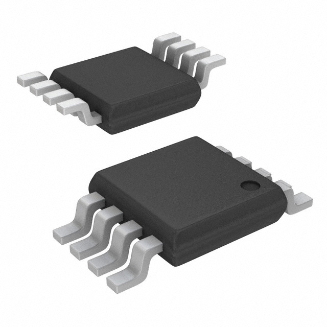
TS4902IDT is housed in an 8-pin Small Outline (SO8) package with standard 1.27mm pitch, surface-mount footprint, and exposed pad not electrically connected. Thermal resistance junction-to-ambient is 150°C/W with recommended PCB copper area.
| Pin/Terminal | Circuit Role | Design Meaning |
|---|---|---|
| 1 (OUT) | BTL Output 1 (Inverting) | Drives one side of speaker; inverted polarity relative to VIN+; must connect to speaker negative terminal in standard BTL layout |
| 2 (IN+) | Non-inverting Input | Accepts audio signal; internal bias sets DC operating point; requires AC coupling via Cin to block source offset |
| 3 (IN−) | Inverting Input | Feedback node tied to Rfeed/Rin divider; sets closed-loop gain (Gv = 2×Rfeed/Rin); high-impedance node |
| 4 (GND) | Analog Ground Reference | Primary return path for input, feedback, and output currents; must be low-impedance star point near device |
| 5 (VCC) | Positive Supply Rail | 2.2–5.5V input; requires ≥100µF bulk bypass (Cs) close to pin to suppress HF THD degradation and supply rail disturbance |
| 6 (BYPASS) | Half-Supply Bias Filter | Connects to 1µF capacitor (Cb) to generate stable virtual ground; determines pop/click softness and low-frequency PSRR |
| 7 (STANDBY) | Active-Low Enable | Pull to GND (≤0.5V) for shutdown; pull to VCC (≥1.5V) for operation; 1µs response time enables fast wake/sleep transitions |
| 8 (OUT) | BTL Output 2 (Non-inverting) | Drives opposite speaker terminal; in-phase with VIN+; connects to speaker positive terminal for net differential drive |
Key Features
| Feature | Design Value |
|---|---|
| BTL Output Architecture | Doubles effective voltage swing across speaker vs. single-ended, quadrupling output power at same supply voltage and reducing even-order distortion |
| Ultra-Low Standby Consumption | 10nA max shutdown current enables multi-year battery life in always-listening portable audio accessories without manual power cycling |
| Pop & Click Suppression | Controlled turn-on via Cin/Cb time constant ratio (τin ≪ τb) minimizes transient spikes-no external mute circuit required |
| Thermal Shutdown Protection | Auto-recovery cutoff at 150°C junction temperature prevents permanent damage during sustained high-power or poor-PCB thermal design |
| Unity-Gain Stable Design | Operates reliably with gain ≥1 using only external resistors-no compensation capacitors needed, simplifying layout and BOM |
Applications
| Mobile Handset Audio | Portable Media Player |
|---|---|
|
Use Scenario: Mono speaker amplification in GSM/UMTS feature phones with shared 3.3V system rail and tight board area. IC Role / Device Role / Timing Role: BTL audio driver delivering full-volume playback while rejecting 217Hz TDMA noise from baseband power supply. Use Value: 77dB PSRR eliminates audible buzz during call setup; 0.7W output drives 8Ω speaker to >90dB SPL without external boost converter. |
Use Scenario: Compact MP3 player with single 3.7V Li-ion cell and stereo-to-mono downmix requirement. IC Role / Device Role / Timing Role: Low-voltage mono amplifier accepting line-level input, providing gain-adjustable output with minimal external components. Use Value: 0.3W @ 3.3V meets loudness target; 10nA standby preserves battery over weeks of idle storage; SO8 footprint fits <100mm² PCB area. |
| Wireless Headset Base Unit | Smart Remote Speaker |
|
Use Scenario: Charging dock/base station for Bluetooth headsets, powering internal speaker during voice prompts and alerts. IC Role / Device Role / Timing Role: Standby-controlled audio driver activated only during voice feedback, synchronized to MCU GPIO. Use Value: Sub-µA quiescent draw during 99% idle time extends dock battery life; <1µs standby response enables instant prompt playback. |
Use Scenario: Battery-powered smart remote with integrated speaker for voice assistant feedback and status tones. IC Role / Device Role / Timing Role: Primary audio output stage interfacing directly with MCU DAC, handling both speech and alert tones. Use Value: 0.1% THD+N ensures clear voice reproduction; 2.2V minimum supply allows operation down to 2.5V battery voltage; SO8 eases automated assembly. |
Equivalent & Alternatives
The following parts are listed as comparable options for similar BTL audio amplifier applications.
| Alternative Part | Technical Difference | Application Difference | Selection Advice |
|---|---|---|---|
| MAX9718ETA+ | Higher 1.4W output @ 5V/8Ω but requires 2.7–5.5V supply; 1.2mA quiescent vs. TS4902's 6mA; no standby pin - uses shutdown enable | Preferred where higher volume is mandatory and board space allows larger decoupling; less suitable for ultra-low-power standby-critical designs | Select MAX9718 when peak SPL >95dB is required and system can tolerate higher static current; verify thermal derating on compact PCBs |
| TAS5342DAPR | Digital-input Class-D amplifier; 2.8W output @ 5V/8Ω; integrated PWM controller; requires I²S input and external LC filter | Targets designs with digital audio sources and need for >85% efficiency; incompatible with analog line-in or DAC outputs | Choose TAS5342 only if system uses I²S audio stream and thermal/power efficiency outweighs analog interface simplicity and BOM count |
Compared with MAX9718ETA+ and TAS5342DAPR, TS4902IDT offers the lowest standby current (10nA vs. µA/mA), simplest analog interface (no I²S or complex enable sequencing), and smallest external component count-making it optimal for cost-sensitive, battery-limited mono audio endpoints.
Availability
TS4902IDT is available at Aetrix Electronics and suitable for mobile handset audio, portable media players, wireless headset base units, and smart remote speakers requiring stable component supply with consistent parametric performance across production lots.
Supply support for TS4902IDT includes scheduled delivery planning, volume procurement assistance, BOM continuity management, traceable sourcing, and lifecycle availability coordination for OEM customers, industrial embedded developers, connected-device designers, and electronics production programs.
Manufacturer
STMicroelectronics is a global semiconductor leader headquartered in Geneva, Switzerland, designing and manufacturing analog, microcontroller, power, and sensor solutions for automotive, industrial, and consumer markets.
The TS4902 belongs to ST's low-voltage audio amplifier product line, engineered specifically for battery-powered portable electronics where ultra-low standby current, BTL efficiency, and GSM-noise immunity are primary design constraints.
FAQ
What is the minimum recommended bypass capacitor value on the VCC pin?
The datasheet specifies a minimum 100µF electrolytic or low-ESR tantalum capacitor (Cs) directly at the VCC pin. Using less than 100µF increases THD+N above 7kHz and reduces PSRR effectiveness due to insufficient high-frequency supply filtering. Ceramic capacitors alone are inadequate; a hybrid approach (e.g., 100µF tantalum + 100nF ceramic) is preferred for broadband decoupling.
Can TS4902IDT drive a 4Ω speaker?
Yes, TS4902IDT supports 4Ω to 32Ω loads per the Absolute Maximum Ratings table. At 5V, it delivers ~0.9W into 4Ω (THD = 1%, 1kHz), but power dissipation rises significantly-thermal derating curves show maximum ambient temperature drops to ~60°C for continuous 4Ω operation. PCB copper area and airflow must be enhanced to avoid thermal shutdown.
How does the standby pin behave electrically?
The STANDBY pin is CMOS-compatible with active-low logic: device enters <10nA shutdown when pin voltage ≤0.5V (GND reference), and operates normally when ≥1.5V (up to VCC). Internal pull-down is absent-external Rstb (typically 100kΩ) is required to ensure defined state during MCU reset. Response time is 1µs, enabling rapid wake-up for voice-triggered applications.
Is external gain-setting resistor matching critical for THD performance?
Yes. The datasheet shows THD+N degrades if Rin and Rfeed tolerance exceeds ±1%. For Gv = 2 (Rin = Rfeed = 22kΩ), use 1% metal-film resistors placed symmetrically near the IN− pin. Mismatch introduces common-mode imbalance, increasing even-order harmonics and reducing PSRR-particularly noticeable below 1kHz where human hearing is most sensitive.
TS4902IDT Specifications
- Product attributes
- Attribute value
- Manufacturer:
- STMicroelectronics
- Series:
- -
- Package/Case:
- 8-SOIC (0.154", 3.90mm Width)
- Packaging:
- Tape & Reel (TR)
- Product Status:
- Obsolete
- Type:
- Class AB
- Output Type:
- 1-Channel (Mono)
- Max Output Power x Channels @ Load:
- 700mW x 1 @ 8Ohm
- Voltage - Supply:
- 2.2V ~ 5.5V
- Features:
- Depop, Standby, Thermal Protection
- Mounting Type:
- Surface Mount
- Operating Temperature:
- -40°C ~ 85°C (TA)
- Grade:
- -
- Qualification:
- -
- Supplier Device Package:
- 8-SOIC
TS4902IDT FAQ
1.How can I place an order for TS4902IDT through Aetrix?
Please submit a Request for Quotation (RFQ) for TS4902IDT on Aetrix. Our sales agent will provide a competitive quotation and guide you through the order confirmation once you accept the terms.
2.Are the price and stock information for TS4902IDT reliable?
The price and inventory of TS4902IDT are updated periodically and may fluctuate due to market conditions. Stock and pricing data are typically refreshed every 24 hours. Quotation validity for TS4902IDT is usually 5 days.
3.What payment methods are accepted for TS4902IDT?
We accept Wire Transfer, PayPal, Credit Card, Western Union, MoneyGram, and Escrow for TS4902IDT transactions.
Note: Certain payment methods may incur a processing fee.
4.How is shipping managed for TS4902IDT?
TS4902IDT orders can be shipped via leading logistics carriers, including DHL, UPS, FedEx, TNT, or Registered Mail.
Once your TS4902IDT order is processed, you will receive an email with the shipment details and tracking number.
Note: Tracking information may take up to 24 hours to appear. Express delivery typically takes 3–5 business days.
5.How can I obtain technical support or documentation for TS4902IDT?
For technical support, including TS4902IDT datasheets, pinout diagrams, or application guidance, please contact our engineering support team. They can provide detailed documentation and assistance for your TS4902IDT requirements.
6.How does Aetrix verify that TS4902IDT is sourced from the original manufacturer or authorized distributors?
All TS4902IDT products on Aetrix are procured from qualified distributors and authorized channels. Our dedicated quality assurance team conducts strict verification, including traceability checks and, if necessary, third-party testing. This ensures that TS4902IDT meets industry standards.
7.What is the process for return or replacement of TS4902IDT?
All TS4902IDT units undergo pre-shipment inspection (PSI). If there is an issue with TS4902IDT, returns or replacements are accepted under the following conditions:
1.Quantity discrepancies, incorrect items, or visible external defects (such as breakage or corrosion), acknowledged by Aetrix.
2.The issue is reported within 90 days of delivery.
3.The TS4902IDT part is unused and in its original packaging.
Return procedure for TS4902IDT:
1.Submit a request within 90 days.
2.Obtain a Return Material Authorization (RMA) from Aetrix.
TS4902IDT Tags
-Exposed-Pad.jpg)
-
TS34119CS RLG
Taiwan Semiconductor Corporation

-
LM386MX-1/NOPB
Texas Instruments

-
TPA711DGNR
Texas Instruments

-
LM386N-4/NOPB
Texas Instruments

-
TS4990IST
STMicroelectronics
-
PAM8302AASCR
Diodes Incorporated
-
TPA6130A2RTJR
Texas Instruments
-
TPA6111A2DGNR
Texas Instruments
-
LM4861MX/NOPB
Texas Instruments
-
LM386M-1/NOPB
Texas Instruments

-
NCS2211DR2G
onsemi
-
IS31AP2005-DLS2-TR
Lumissil Microsystems
Tech Hub

A practical engineering and sourcing framework covering lifecycle verification, lifetime-buy calculations, replacement qualification, supplier checks and counterfeit-risk controls.

TTL and CMOS logic families differ in thresholds, loading, output drive, power and timing. This engineering guide compares 74HC and 74HCT, calculates noise margins and checks 3.3 V/5 V compatibility.

A practical engineering guide to 3.3V and 5V logic compatibility, input thresholds, resistor dividers, translator ICs, MOSFET level shifting, I2C pull-ups, timing limits and power-sequencing risks.

The 74HC595 uses push-pull logic outputs, while the TPIC6B595 uses 50 V open-drain DMOS sinks for higher-power loads. This guide compares timing, current limits, 3.3 V interfacing, load wiring, thermal…

The 74HC595 converts serial data into eight stable parallel outputs. This guide covers pin functions, shift and storage timing, OE and MR behavior, drive-current limits, cascading, voltage compatibilit…

A technical comparison of level-sensitive latches and edge-triggered flip-flops, covering timing windows, setup and hold limits, master–slave operation, time borrowing, race-through, HDL inference and…

A D latch stores one bit while Enable controls when data can pass. This reference covers gate-level operation, truth tables, transparency, setup and hold timing, LE versus OE, common ICs and practical …

An SR latch stores one bit through cross-coupled feedback. This engineering reference covers NOR and NAND implementations, truth tables, forbidden-state recovery, gated operation, switch debouncing, fa…

Latch circuits retain one bit through feedback. This technical reference covers SR and D latches, truth tables, transparency, timing limits, latch-versus-flip-flop behavior, applications and common log…

An engineering guide to LED driver operation, constant-current and constant-voltage outputs, linear and switching topologies, dimming, IC selection, calculations, replacement compatibility, and fault c…


