
 My Inquiry
 My Account


Texas Instruments UCD9240PFCR
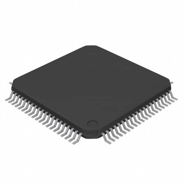
- Part No.:
- UCD9240PFCR
- Manufacturer:
- Texas Instruments
- Category:
- Power Management - Specialized
- Package:
- 80-TQFP
- Datasheet:
-
 UCD9240PFCR.pdf
- Description:
- IC DGTL PWM SYSTEM CTRLR 80-TQFP
- Quantity:
- Payment:

- Shipping:

Inventory:2,108
Please send an inquiry. Send us your inquiry, and we will respond immediately.
Product details
Overview
UCD9240PFCR from Texas Instruments is a digital PWM system controller for multi-rail, multi-phase non-isolated synchronous buck DC/DC power supplies. It controls up to four voltage rails and eight phases, supports switching frequencies up to 2 MHz with 250 ps duty-cycle resolution, delivers up to 1 mV closed-loop resolution, and integrates hardware-accelerated 3-pole/3-zero digital compensators. It is deployed in high-density server and telecom power systems requiring precise sequencing, margining, and real-time current/temperature balancing.
For engineers reviewing the UCD9240PFCR datasheet, UCD9240PFCR pinout, UCD9240PFCR application, or UCD9240PFCR equivalent, this page provides verified technical context, validated pin functions, confirmed rail-phase configuration limits, documented fault response latencies (e.g., <300 µs overvoltage detection), and real-world alternative selection guidance based on TI's official documentation and package-specific electrical specifications.
Technical Context
The UCD9240PFCR implements an ARM7-based digital control architecture with dedicated Fusion Digital Power peripherals, including four independent error amplifier/digital compensator chains feeding eight DPWM outputs. Each rail uses a 12-bit ADC with configurable gain (AFE_GAIN) and analog comparator-based overcurrent protection with 31.25 mV threshold resolution.
It features dual-domain power management: analog front-end inputs (EAp/EAn, CS-xA/B, Temp, Vin/Iin) feed into a continuous ADC monitoring sequence (23–61.44 µs per full scan), while hardware fault detectors (analog comparators, FAULT pins) operate independently with sub-µs latency-enabling simultaneous fast-response protection and high-resolution closed-loop regulation.
Key Specifications
| Parameter | Value and Actual Design Meaning |
|---|---|
| Max Output Rails | 4 independent voltage rails - enables single-controller management of core, I/O, memory, and auxiliary supplies in FPGA/DSP systems. |
| Max Phases per Rail | 8 total phases - supports high-current rails (e.g., CPU VDD) via interleaved phase shedding and current balancing. |
| Switching Frequency | 15.26 kHz to 2 MHz - allows optimization for efficiency (low-freq) or size (high-freq) without external clock source. |
| Duty-Cycle Resolution | 250 ps - enables fine-grained transient response tuning and stable operation at low duty cycles (<5%) in high-input-voltage applications. |
| Closed-Loop Resolution | 1 mV - achieves tight output regulation (±0.5% typical) across load/line/temperature for sensitive logic supplies. |
| Fault Response Time | <300 µs for over/under-voltage - meets IPC-9592B Class 2 safety timing requirements for server VRMs. |
| ADC Monitoring Interval | 23.04–61.44 µs full-sequence - ensures real-time visibility into all rail voltages, currents, and temperatures for dynamic thermal management. |
Pinout & Package
The UCD9240PFCR is housed in an 80-pin TQFP (PFC) package with exposed thermal pad, rated for –40°C to 110°C operation. Pin assignments are electrically and functionally identical to the UCD9240PFC variant; differences are limited to packaging and reel/tray orientation.
| Pin/Terminal | Circuit Role | Design Meaning |
|---|---|---|
| EAp1–EAp4 / EAn1–EAn4 | Differential error amplifier inputs | Accept ±Vsense signals for four independent voltage feedback loops; support rail-specific compensation via programmable 3P3Z filters. |
| DPWM-1A to DPWM-4B | Digital PWM outputs | Eight high-resolution (250 ps) DPWM signals driving external gate drivers; support phase interleaving and adding/shedding. |
| CS-1A to CS-4B | Current sense analog inputs | Interface with shunt-based current sensing; feed analog comparators for hardware-fast overcurrent detection and ADC for digital monitoring. |
| FAULT-1A to FAULT-4B | External fault inputs | Asynchronous active-low inputs accepting external fault signals (e.g., from driver ICs or thermal switches) to trigger immediate rail shutdown. |
| SRE-1A to SRE-4B | Synchronous rectifier enable | Directly control external MOSFETs in synchronous buck topologies; timed to avoid shoot-through with corresponding DPWM edges. |
| PMBus_Clk / PMBus_Data | PMBus v1.2 interface | Supports standard PMBus commands (READ_VIN, STORE_DEFAULT_ALL, OPERATION) at up to 1 MHz for configuration, telemetry, and fault logging. |
Key Features
| Feature | Design Value |
|---|---|
| Hardware-accelerated 3P3Z compensator | Enables stable loop closure without external components; supports automatic coefficient switching during load transients via preloaded filter banks. |
| Voltage tracking & sequencing | Programmable ramp rates and delay offsets allow precise power-up/down ordering of multiple rails (e.g., core before I/O) to prevent latch-up in FPGAs. |
| Phase adding/shedding | Dynamically enables/disables phases based on load current to maintain >90% efficiency across 5–100% load range in server VRMs. |
| 12-bit ADC with 4x gain options | Configurable AFE_GAIN (1/4/1/8) extends measurable voltage range from 0–2.5 V while preserving 1 mV effective resolution at 1 V setpoint. |
| Nonvolatile memory with ECC | Stores full configuration (compensators, margins, faults) in on-chip flash; 20k write cycles and 100-year data retention ensure field reliability without battery backup. |
Applications
| Server VRM Control | Telecom Rectifier Module |
|---|---|
Use Scenario: Regulating CPU core (0.8–1.2 V), memory (1.2 V), and PCIe (3.3 V) rails in 1U rack servers with dynamic load steps up to 100 A/µs. IC Role / Device Role / Timing Role: Primary digital PWM controller managing eight-phase CPU rail + dual-phase memory rail; executes closed-loop control every 200 µs with hardware fault cutoff <300 µs. Use Value: Eliminates discrete op-amps, compensators, and sequencers; reduces BOM count by 12+ components while enabling PMBus-based remote firmware updates. | Use Scenario: Controlling dual-output (–48 V primary, +12 V auxiliary) DC/DC stages in telecom shelf power systems with strict -40°C to +70°C operating range. IC Role / Device Role / Timing Role: Multi-rail system controller coordinating voltage tracking between primary and auxiliary outputs; uses Sync_In/Out to align clocks across redundant controllers. Use Value: Achieves ±0.5% output accuracy over temperature and line, with automatic phase shedding to sustain >94% efficiency at 30% load-meeting NEBS Level 3 compliance. |
| FPGA Power Management | Storage System PSU |
Use Scenario: Supplying configurable I/O banks (1.8 V, 2.5 V, 3.3 V) and transceiver rails (1.0 V) in high-end Xilinx/Intel FPGAs with prebias start-up and dynamic voltage scaling. IC Role / Device Role / Timing Role: Sequencing and margining controller; applies soft-start with user-defined dV/dt to prevent inrush into partially powered devices during hot-swap events. Use Value: Supports prebias start-up without output shorting; enables real-time voltage margining (±5%) via PMBus for production test and lifetime reliability screening. | Use Scenario: Managing 12 V input-to-5 V/3.3 V/1.8 V conversion for NVMe SSD arrays with fan-cooled heatsinks and thermal derating thresholds. IC Role / Device Role / Timing Role: Thermal-aware power controller; reads internal and external temperature sensors every 800 ms, triggers fan PWM control, and initiates current foldback at 100°C junction. Use Value: Integrates fan tachometer input, PWM output, and thermal shutdown-replacing discrete fan controllers and analog thermal monitors in compact storage enclosures. |
Equivalent & Alternatives
The following parts are listed as comparable options for similar multi-phase digital PWM controller applications.
| Alternative Part | Technical Difference | Application Difference | Selection Advice |
|---|---|---|---|
| UCD9244RGCT | 64-pin QFN package; supports only 4 phases (vs. 8); lacks CS-3B/CS-4B inputs and SRE-3B/SRE-4B outputs. | Targeted at space-constrained, lower-power applications (≤300 W); not suitable for 8-phase CPU VRMs. | Select when board area is critical and phase count ≤4; verify thermal pad layout matches RGC footprint. |
| LM25069SWX/NOPB | Analog hot-swap controller with integrated MOSFET drive; no DPWM, no multi-rail sequencing, no PMBus. | Used for input-stage protection only-not a functional replacement for digital power control. | Choose only for standalone inrush limiting; cannot substitute for UCD9240PFCR's regulation, monitoring, or sequencing capabilities. |
Compared with UCD9240PFCR, the UCD9244RGCT offers identical digital control architecture but reduced phase count and I/O in a smaller package, while the LM25069SWX/NOPB serves a fundamentally different circuit role-input protection versus full digital power management-making it unsuitable as a functional alternative.
Availability
UCD9240PFCR is available at Aetrix Electronics and suitable for server VRM design, telecom rectifier modules, FPGA power sequencing, and storage system PSUs requiring stable component supply, long-term lifecycle support, and traceable sourcing.
Supply support for UCD9240PFCR includes scheduled delivery planning, volume procurement assistance, BOM continuity management, traceable sourcing, and lifecycle availability coordination for OEM customers, industrial embedded developers, connected-device designers, and electronics production programs.
Manufacturer
Texas Instruments is a global semiconductor leader specializing in analog, embedded processing, and power management technologies, with decades of expertise in high-reliability power control ICs.
The UCD9240PFCR belongs to TI's Fusion Digital Power™ controller family, designed specifically for digitally programmable, multi-phase, non-isolated DC/DC converters in enterprise computing and communications infrastructure.
FAQ
What is the maximum number of phases supported by the UCD9240PFCR?
The UCD9240PFCR supports up to eight total phases across up to four voltage rails. This is explicitly defined in the device description and functional block diagram, and confirmed by the pinout (eight DPWM outputs: DPWM-1A through DPWM-4B). Phase allocation is flexible-e.g., 4+2+1+1 or 2+2+2+2-and managed via configuration registers stored in on-chip flash memory.
Does the UCD9240PFCR require external compensation components?
No, the UCD9240PFCR does not require external compensation components. It integrates hardware-accelerated 3-pole/3-zero digital compensators with programmable coefficients stored in flash. The device supports multiple filter banks that can be switched dynamically during operation, eliminating the need for external RC networks or op-amp-based analog compensation circuits.
What communication interface does the UCD9240PFCR use for configuration and telemetry?
The UCD9240PFCR uses a PMBus v1.2-compliant interface (compatible with SMBus and I²C) for configuration, telemetry, and fault logging. It supports standard PMBus commands including OPERATION, READ_VOUT, STORE_DEFAULT_ALL, and MFR_SPECIFIC commands. The interface operates up to 1 MHz and includes dedicated Alert and Cntl pins for interrupt-driven event reporting.
Can the UCD9240PFCR perform voltage margining and sequencing?
Yes, the UCD9240PFCR natively supports both voltage margining and sequencing. It provides programmable positive/negative margining (±5% typical) via PMBus commands and supports complex power-up/down sequences-including programmable delays, ramp rates, and inter-rail dependencies-for up to four rails. These functions are implemented in firmware and stored in nonvolatile memory.
What is the operating temperature range for the UCD9240PFCR?
The UCD9240PFCR is specified for an operating free-air temperature range of –40°C to 110°C, as stated in the Recommended Operating Conditions table. This extended range supports deployment in demanding environments such as base station power supplies and industrial server backplanes where ambient temperatures exceed commercial-grade limits.
UCD9240PFCR Specifications
- Product attributes
- Attribute value
- Manufacturer:
- Texas Instruments
- Series:
- Fusion Digital Power™
- Package/Case:
- 80-TQFP
- Packaging:
- Tape & Reel (TR)
- Product Status:
- Active
- Applications:
- Special Purpose
- Current - Supply:
- -
- Voltage - Supply:
- 3V ~ 3.6V
- Operating Temperature:
- -40°C ~ 110°C
- Grade:
- -
- Qualification:
- -
- Mounting Type:
- Surface Mount
- Supplier Device Package:
- 80-TQFP (12x12)
UCD9240PFCR FAQ
1.How can I place an order for UCD9240PFCR through Aetrix?
Please submit a Request for Quotation (RFQ) for UCD9240PFCR on Aetrix. Our sales agent will provide a competitive quotation and guide you through the order confirmation once you accept the terms.
2.Are the price and stock information for UCD9240PFCR reliable?
The price and inventory of UCD9240PFCR are updated periodically and may fluctuate due to market conditions. Stock and pricing data are typically refreshed every 24 hours. Quotation validity for UCD9240PFCR is usually 5 days.
3.What payment methods are accepted for UCD9240PFCR?
We accept Wire Transfer, PayPal, Credit Card, Western Union, MoneyGram, and Escrow for UCD9240PFCR transactions.
Note: Certain payment methods may incur a processing fee.
4.How is shipping managed for UCD9240PFCR?
UCD9240PFCR orders can be shipped via leading logistics carriers, including DHL, UPS, FedEx, TNT, or Registered Mail.
Once your UCD9240PFCR order is processed, you will receive an email with the shipment details and tracking number.
Note: Tracking information may take up to 24 hours to appear. Express delivery typically takes 3–5 business days.
5.How can I obtain technical support or documentation for UCD9240PFCR?
For technical support, including UCD9240PFCR datasheets, pinout diagrams, or application guidance, please contact our engineering support team. They can provide detailed documentation and assistance for your UCD9240PFCR requirements.
6.How does Aetrix verify that UCD9240PFCR is sourced from the original manufacturer or authorized distributors?
All UCD9240PFCR products on Aetrix are procured from qualified distributors and authorized channels. Our dedicated quality assurance team conducts strict verification, including traceability checks and, if necessary, third-party testing. This ensures that UCD9240PFCR meets industry standards.
7.What is the process for return or replacement of UCD9240PFCR?
All UCD9240PFCR units undergo pre-shipment inspection (PSI). If there is an issue with UCD9240PFCR, returns or replacements are accepted under the following conditions:
1.Quantity discrepancies, incorrect items, or visible external defects (such as breakage or corrosion), acknowledged by Aetrix.
2.The issue is reported within 90 days of delivery.
3.The UCD9240PFCR part is unused and in its original packaging.
Return procedure for UCD9240PFCR:
1.Submit a request within 90 days.
2.Obtain a Return Material Authorization (RMA) from Aetrix.
UCD9240PFCR Tags

-
TPS2511DGNR
Texas Instruments

-
UTC2000/MG
Microchip Technology

-
TUSB320HAIRWBR
Texas Instruments

-
TPS61252DSGR
Texas Instruments

-
PI5USB30216CXUAEX
Diodes Incorporated

-
SN6501DBVR
Texas Instruments

-
CYPD3177-24LQXQT
Infineon Technologies
-
SN6501QDBVRQ1
Texas Instruments

-
STUSB1600AQTR
STMicroelectronics

-
SN6505BDBVR
Texas Instruments
-
SN6501DBVT
Texas Instruments

-
TPS65150PWPR
Texas Instruments
Tech Hub

A practical engineering guide to 3.3V and 5V logic compatibility, input thresholds, resistor dividers, translator ICs, MOSFET level shifting, I2C pull-ups, timing limits and power-sequencing risks.

The 74HC595 uses push-pull logic outputs, while the TPIC6B595 uses 50 V open-drain DMOS sinks for higher-power loads. This guide compares timing, current limits, 3.3 V interfacing, load wiring, thermal…

The 74HC595 converts serial data into eight stable parallel outputs. This guide covers pin functions, shift and storage timing, OE and MR behavior, drive-current limits, cascading, voltage compatibilit…

A technical comparison of level-sensitive latches and edge-triggered flip-flops, covering timing windows, setup and hold limits, master–slave operation, time borrowing, race-through, HDL inference and…

A D latch stores one bit while Enable controls when data can pass. This reference covers gate-level operation, truth tables, transparency, setup and hold timing, LE versus OE, common ICs and practical …

An SR latch stores one bit through cross-coupled feedback. This engineering reference covers NOR and NAND implementations, truth tables, forbidden-state recovery, gated operation, switch debouncing, fa…

Latch circuits retain one bit through feedback. This technical reference covers SR and D latches, truth tables, transparency, timing limits, latch-versus-flip-flop behavior, applications and common log…

An engineering guide to LED driver operation, constant-current and constant-voltage outputs, linear and switching topologies, dimming, IC selection, calculations, replacement compatibility, and fault c…

Operational amplifier guide covering op amp basics, feedback, ideal vs real op amps, common configurations, buffer circuits, offset, bias current, gain-bandwidth, slew rate, rail-to-rail limits and sel…

Jumper cables guide covering safe connection order, red and black clamp placement, final ground connection, cable gauge, length, clamp quality, copper vs CCA cables, jump starter comparison and battery…


