Vishay General Semiconductor - Diodes Division 1.5SMC480A-E3/9AT
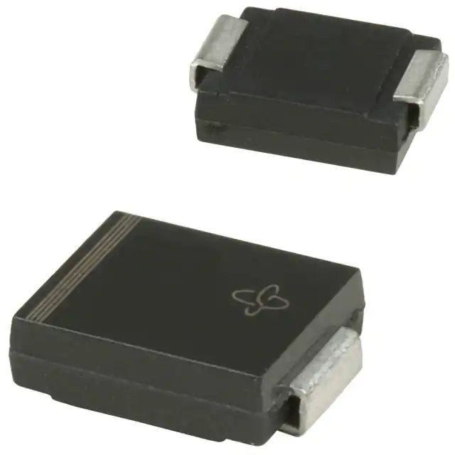
- Part No.:
- 1.5SMC480A-E3/9AT
- Manufacturer:
- Vishay General Semiconductor - Diodes Division
- Category:
- TVS Diodes
- Package:
- DO-214AB, SMC
- Datasheet:
-
1.5SMC480A-E3/9AT.pdf
- Description:
- TVS DIODE 408VWM 658VC SMC
- Quantity:
- Payment:

- Shipping:

Inventory:9,789
Please send an inquiry. Send us your inquiry, and we will respond immediately.
Product details
Overview
1.5SMC480A-E3/9AT from Vishay General Semiconductor is a unidirectional surface-mount Transient Voltage Suppressor (TVS) diode in the SMC (DO-214AB) package, rated for 480 V standoff voltage (VWM), 504 V maximum breakdown voltage (VBR), and 1500 W peak pulse power (10/1000 µs). It clamps transients to 658 V at 2.28 A peak pulse current and operates from –65 °C to +150 °C - deployed for primary overvoltage protection on high-voltage DC bus lines in industrial power supplies.
For engineers reviewing the 1.5SMC480A-E3/9AT datasheet, 1.5SMC480A-E3/9AT pinout, 1.5SMC480A-E3/9AT application, or 1.5SMC480A-E3/9AT equivalent, key selection criteria include its 408 V minimum stand-off voltage, low 0.11 %/°C temperature coefficient of VBR, RoHS-compliant matte tin-plated leads, MSL Level 1 rating, and suitability for automated SMT placement on 8.0 mm × 8.0 mm copper pads.
Technical Context
This unidirectional TVS diode uses a glass-passivated silicon junction to achieve fast response time (<1 ns) and low incremental surge resistance, enabling effective suppression of lightning-induced surges and inductive switching transients. Its 1500 W peak pulse power rating is specified under standardized 10/1000 µs waveform conditions with 0.01 % duty cycle.
The device exhibits a typical thermal resistance of 75 °C/W (junction-to-ambient) and 15 °C/W (junction-to-leads), supporting reliable operation at up to 150 °C junction temperature. Polarity is marked by a cathode band; it is not bidirectional and does not support reverse-biased transient suppression.
Key Specifications
| Parameter | Value and Actual Design Meaning |
|---|---|
| VWM (Stand-off Voltage) | 408 V - Maximum continuous reverse operating voltage before clamping begins; defines safe DC operating margin. |
| VBR (Breakdown Voltage) | 456–504 V at 1 mA - Voltage at which device enters avalanche conduction; ensures predictable turn-on threshold. |
| VC (Clamping Voltage) | 658 V at IPPM = 2.28 A - Peak voltage seen by protected circuit during 10/1000 µs transient; determines downstream component stress. |
| PPPM (Peak Pulse Power) | 1500 W - Maximum transient energy absorption capability under standard 10/1000 µs waveform; critical for surge immunity compliance. |
| TJ max. | +150 °C - Maximum allowable junction temperature; enables use in high-ambient industrial environments without derating. |
| Package | SMC (DO-214AB) - Surface-mount outline with 8.13 mm × 6.22 mm footprint and 3.20 mm height; optimized for automated placement and thermal pad layout. |
| RoHS Compliance | E3 suffix - Lead-free, halogen-free, and compliant with JEDEC J-STD-020 MSL Level 1 (260 °C peak reflow). |
Pinout & Package
Package: SMC (DO-214AB), surface-mount, molded plastic case with matte tin-plated leads. Cathode indicated by a band on the body; anode is unmarked end. Mounting requires 0.31" × 0.31" (8.0 mm × 8.0 mm) copper pads per terminal per Vishay specification.
| Pin/Terminal | Circuit Role | Design Meaning |
|---|---|---|
| Cathode (banded end) | Transient current sink | Connected to protected line; conducts surge current to ground when voltage exceeds VBR. |
| Anode (unmarked end) | Reference / return path | Typically tied to system ground or low-impedance return; completes clamping path during overvoltage events. |
Key Features
| Feature | Design Value |
|---|---|
| 1500 W peak pulse power (10/1000 µs) | Enables robust protection against IEC 61000-4-5 Level 4 surges (4 kV line-earth) on high-voltage rails. |
| Low incremental surge resistance | Minimizes clamping voltage overshoot during fast-rising transients, reducing stress on downstream MOSFETs or controllers. |
| Glass passivated chip junction | Ensures long-term reliability and stable VBR performance across temperature and lifetime under repeated surge stress. |
| MSL Level 1, 260 °C peak reflow | Supports standard lead-free SMT assembly without moisture sensitivity concerns or baking requirements. |
| Automated placement compatibility | Standardized SMC outline and lead geometry allow direct integration into high-speed pick-and-place workflows. |
Applications
| Industrial DC Power Supply Protection | Telecom Rectifier Output Clamping |
|---|---|
Use Scenario: Protecting 400–500 V DC output stages of telecom rectifiers against load dump and lightning-induced surges. IC Role / Device Role / Timing Role: Unidirectional TVS placed between output rail and chassis ground to clamp positive-going transients above 408 V. Use Value: Limits transient voltage to ≤658 V, safeguarding downstream DC-DC converters and monitoring ICs rated for 700 V absolute maximum. |
Use Scenario: Overvoltage protection on high-voltage auxiliary power rails in base station RF amplifiers. IC Role / Device Role / Timing Role: Standoff-rated TVS absorbing repetitive switching spikes from GaN FET gate drivers and boost converters. Use Value: Maintains <1 µA leakage at 408 V, preventing standby power loss while delivering 1500 W surge capacity for MIL-STD-1275B compliance. |
| Renewable Energy Inverter DC Link | Railway Signaling Power Input |
Use Scenario: Clamping induced transients on 600 V-class photovoltaic inverter DC link capacitors during grid fault recovery. IC Role / Device Role / Timing Role: Primary transient suppressor mounted directly across DC bus terminals to shunt surge energy before reaching IGBT modules. Use Value: Withstands 2.28 A peak pulse current and 150 °C junction temperature, ensuring reliability in outdoor, thermally demanding solar farms. |
Use Scenario: Protecting 48–110 V DC input stages of railway signaling controllers exposed to traction return current transients. IC Role / Device Role / Timing Role: High-VWM TVS used in series with lower-voltage devices to extend clamping range beyond 400 V in multi-stage protection networks. Use Value: Provides precise 408 V standoff with ±5 % VBR tolerance, enabling coordinated staging with 330 V and 275 V TVS devices in EN 50155-compliant designs. |
Equivalent & Alternatives
The following parts are listed as comparable options for similar transient voltage suppression applications.
| Alternative Part | Technical Difference | Application Difference | Selection Advice |
|---|---|---|---|
| SMBJ480A-E3/52T | Lower peak pulse power (600 W), SMB package (smaller footprint, higher RθJA = 100 °C/W) | Not suitable for 1500 W surge requirements; limited to lower-energy transients in space-constrained layouts. | Select only if board area is critical and surge threat level is ≤IEC 61000-4-5 Level 2. |
| 1.5KE480A | Through-hole DO-201 package, identical electrical specs but incompatible with SMT assembly and higher thermal resistance. | Requires manual or wave soldering; unsuitable for automated production or high-density PCBs. | Choose only for legacy through-hole designs or prototyping where reflow compatibility is not required. |
Compared with SMBJ480A-E3/52T and 1.5KE480A, the 1.5SMC480A-E3/9AT uniquely delivers 1500 W SMT-compatible surge protection in a thermally optimized SMC package with MSL Level 1 reflow readiness - making it the only option meeting both high-power and high-volume manufacturing requirements.
Availability
1.5SMC480A-E3/9AT is available at Aetrix Electronics and suitable for industrial power supplies, telecom rectifiers, renewable energy inverters, and railway signaling systems requiring stable component supply and full traceability.
Supply support for 1.5SMC480A-E3/9AT includes scheduled delivery planning, volume procurement assistance, BOM continuity management, traceable sourcing, and lifecycle availability coordination for OEM customers, industrial embedded developers, connected-device designers, and electronics production programs.
Manufacturer
Vishay General Semiconductor is a global leader in discrete semiconductors, specializing in diodes, rectifiers, TVS devices, and optoelectronics with emphasis on reliability, power handling, and automotive-grade qualification.
The 1.5SMC Series was designed specifically for high-energy transient suppression in industrial, telecom, and transportation systems - prioritizing robustness, standardized SMT compatibility, and AEC-Q101 qualification paths for mission-critical applications.
FAQ
What is the clamping voltage of the 1.5SMC480A-E3/9AT under a 10/1000 µs surge?
The 1.5SMC480A-E3/9AT clamps to a maximum of 658 V when subjected to its rated peak pulse current of 2.28 A under the standardized 10/1000 µs waveform. This value is measured per Figure 1 in Vishay document 88303 and defines the upper voltage limit imposed on protected circuitry during transient events.
Is the 1.5SMC480A-E3/9AT bidirectional or unidirectional?
The 1.5SMC480A-E3/9AT is a unidirectional TVS diode, as confirmed by its "A" suffix and cathode band marking. It conducts only during positive voltage excursions relative to its cathode; it does not suppress reverse-polarity transients. Bidirectional variants use the "CA" suffix (e.g., 1.5SMC480CA).
What is the standoff voltage (VWM) rating for the 1.5SMC480A-E3/9AT?
The 1.5SMC480A-E3/9AT has a standoff voltage (VWM) of 408 V, meaning it remains non-conductive up to this DC or RMS voltage level. This value is derived from the 10 % tolerance below its minimum breakdown voltage (VBR min = 456 V) and is critical for ensuring no leakage or false triggering in 400 V-class systems.
Does the 1.5SMC480A-E3/9AT meet automotive qualification standards?
No - the 1.5SMC480A-E3/9AT is a commercial-grade part with E3 suffix (RoHS-compliant, MSL Level 1). Automotive-qualified versions carry HE3 or HM3 suffixes and revision codes (e.g., 1.5SMC480AHE3_B/I); those are explicitly rated to AEC-Q101. The 1.5SMC480A-E3/9AT is intended for industrial and telecom use.
What is the thermal resistance and maximum junction temperature of the 1.5SMC480A-E3/9AT?
The 1.5SMC480A-E3/9AT has a typical junction-to-ambient thermal resistance (RθJA) of 75 °C/W and a maximum junction temperature (TJ max.) of +150 °C. These values assume mounting on 0.31" × 0.31" copper pads per Vishay's recommended layout - essential for sustaining repetitive surge duty cycles without thermal runaway.
1.5SMC480A-E3/9AT Specifications
- Product attributes
- Attribute value
- Manufacturer:
- Vishay General Semiconductor - Diodes Division
- Package/Case:
- DO-214AB, SMC
- Series:
- 1.5SMC, TransZorb®
- Packaging:
- Tape & Reel (TR)
- Product Status:
- Obsolete
- Type:
- Zener
- Unidirectional Channels:
- 1
- Bidirectional Channels:
- -
- Voltage - Reverse Standoff (Typ):
- 408V
- Voltage - Breakdown (Min):
- 456V
- Voltage - Clamping (Max) @ Ipp:
- 658V
- Current - Peak Pulse (10/1000µs):
- 2.28A
- Power - Peak Pulse:
- 1500W (1.5kW)
- Power Line Protection:
- No
- Applications:
- General Purpose
- Capacitance @ Frequency:
- -
- Operating Temperature:
- -65°C ~ 150°C (TJ)
- Grade:
- -
- Qualification:
- -
- Mounting Type:
- Surface Mount
- Supplier Device Package:
- DO-214AB (SMCJ)
1.5SMC480A-E3/9AT FAQ
1.How can I place an order for 1.5SMC480A-E3/9AT through Aetrix?
Please submit a Request for Quotation (RFQ) for 1.5SMC480A-E3/9AT on Aetrix. Our sales agent will provide a competitive quotation and guide you through the order confirmation once you accept the terms.
2.Are the price and stock information for 1.5SMC480A-E3/9AT reliable?
The price and inventory of 1.5SMC480A-E3/9AT are updated periodically and may fluctuate due to market conditions. Stock and pricing data are typically refreshed every 24 hours. Quotation validity for 1.5SMC480A-E3/9AT is usually 5 days.
3.What payment methods are accepted for 1.5SMC480A-E3/9AT?
We accept Wire Transfer, PayPal, Credit Card, Western Union, MoneyGram, and Escrow for 1.5SMC480A-E3/9AT transactions.
Note: Certain payment methods may incur a processing fee.
4.How is shipping managed for 1.5SMC480A-E3/9AT?
1.5SMC480A-E3/9AT orders can be shipped via leading logistics carriers, including DHL, UPS, FedEx, TNT, or Registered Mail.
Once your 1.5SMC480A-E3/9AT order is processed, you will receive an email with the shipment details and tracking number.
Note: Tracking information may take up to 24 hours to appear. Express delivery typically takes 3–5 business days.
5.How can I obtain technical support or documentation for 1.5SMC480A-E3/9AT?
For technical support, including 1.5SMC480A-E3/9AT datasheets, pinout diagrams, or application guidance, please contact our engineering support team. They can provide detailed documentation and assistance for your 1.5SMC480A-E3/9AT requirements.
6.How does Aetrix verify that 1.5SMC480A-E3/9AT is sourced from the original manufacturer or authorized distributors?
All 1.5SMC480A-E3/9AT products on Aetrix are procured from qualified distributors and authorized channels. Our dedicated quality assurance team conducts strict verification, including traceability checks and, if necessary, third-party testing. This ensures that 1.5SMC480A-E3/9AT meets industry standards.
7.What is the process for return or replacement of 1.5SMC480A-E3/9AT?
All 1.5SMC480A-E3/9AT units undergo pre-shipment inspection (PSI). If there is an issue with 1.5SMC480A-E3/9AT, returns or replacements are accepted under the following conditions:
1.Quantity discrepancies, incorrect items, or visible external defects (such as breakage or corrosion), acknowledged by Aetrix.
2.The issue is reported within 90 days of delivery.
3.The 1.5SMC480A-E3/9AT part is unused and in its original packaging.
Return procedure for 1.5SMC480A-E3/9AT:
1.Submit a request within 90 days.
2.Obtain a Return Material Authorization (RMA) from Aetrix.
1.5SMC480A-E3/9AT Tags

-
ESD9B5.0ST5G
onsemi

-
DESD3V3E1BL-7B
Diodes Incorporated

-
ESD5Z3.3T1G
onsemi

-
D5V0H1B2LP-7B
Diodes Incorporated

-
D5V0P1B2LP-7B
Diodes Incorporated

-
DESD5V0U1BA-7
Diodes Incorporated

-
ESD5Z5.0T1G
onsemi

-
DESD5V0U1BB-7
Diodes Incorporated

-
D12V0L1B2LP-7B
Diodes Incorporated

-
PESD2V0Y1BSFYL
Nexperia USA Inc.

-
DF2S5M4CT,L3F
Toshiba Semiconductor and Storage

-
D5V0L1B2WS-7
Diodes Incorporated
Tech Hub

Schmitt triggers use separate rising and falling thresholds to stabilize slow or noisy signals. This guide covers hysteresis, 74HC14 and 74HCT14 selection, comparator calculations, RC oscillators and p…
Counterfeit components can hide behind convincing markings and passing basic function tests. This engineering reference covers source traceability, external inspection, X-ray, XRF, electrical testing, …
A practical engineering and sourcing framework covering lifecycle verification, lifetime-buy calculations, replacement qualification, supplier checks and counterfeit-risk controls.
TTL and CMOS logic families differ in thresholds, loading, output drive, power and timing. This engineering guide compares 74HC and 74HCT, calculates noise margins and checks 3.3 V/5 V compatibility.
A practical engineering guide to 3.3V and 5V logic compatibility, input thresholds, resistor dividers, translator ICs, MOSFET level shifting, I2C pull-ups, timing limits and power-sequencing risks.
The 74HC595 uses push-pull logic outputs, while the TPIC6B595 uses 50 V open-drain DMOS sinks for higher-power loads. This guide compares timing, current limits, 3.3 V interfacing, load wiring, thermal…
The 74HC595 converts serial data into eight stable parallel outputs. This guide covers pin functions, shift and storage timing, OE and MR behavior, drive-current limits, cascading, voltage compatibilit…
A technical comparison of level-sensitive latches and edge-triggered flip-flops, covering timing windows, setup and hold limits, master–slave operation, time borrowing, race-through, HDL inference and…
A D latch stores one bit while Enable controls when data can pass. This reference covers gate-level operation, truth tables, transparency, setup and hold timing, LE versus OE, common ICs and practical …
An SR latch stores one bit through cross-coupled feedback. This engineering reference covers NOR and NAND implementations, truth tables, forbidden-state recovery, gated operation, switch debouncing, fa…










