
 My Inquiry
 My Account


Microchip Technology ATA5275-PGPI
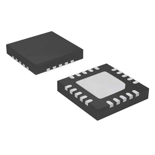
- Part No.:
- ATA5275-PGPI
- Manufacturer:
- Microchip Technology
- Category:
- RFID, RF Access, Monitoring ICs
- Package:
- 20-VQFN Exposed Pad
- Datasheet:
-
 ATA5275-PGPI.pdf
- Description:
- IC TPMS 125KHZ 20QFN
- Quantity:
- Payment:

- Shipping:

Inventory:2,545
Please send an inquiry. Send us your inquiry, and we will respond immediately.
Product details
Overview
ATA5275-PGPI from Microchip Technology (formerly Atmel) is a 125 kHz, 1.5A peak current BCDMOS antenna driver IC designed as a wake-up channel transmitter for tire pressure measurement (TPM) systems. It integrates a self-tuning VCO, adjustable antenna peak current regulation, bi-directional single-wire DIO interface, and built-in 5V regulator delivering up to 10 mA - enabling magnetic field generation and ASK-modulated data/power transmission to TPMS sensors.
For engineers reviewing the ATA5275-PGPI datasheet, ATA5275-PGPI pinout, ATA5275-PGPI application, or ATA5275-PGPI equivalent, this page delivers verified technical context, validated pin functions, automotive-grade diagnosis features, LF transmission timing parameters, and real-world TPM system integration guidance - all grounded in the official Rev. 4739I–AUTO–01/06 specification.
Technical Context
The ATA5275-PGPI implements a dual-mode VCO: self-oscillating at 115–135 kHz (±8%) with REXT bias, and resonance-tracking mode locked to antenna LC tank frequency (90–160 kHz) via SENSE pin zero-crossing detection. Its half-bridge driver uses DMOS technology with 0.3–0.7 Ω RDSON (both sides) and duty-cycle-regulated output to stabilize antenna current across 8–24 V supply range.
Control logic executes ASK modulation by switching DRV outputs on DIO low (square wave) or grounding them on DIO high. Diagnostics monitor DVCC under-voltage (6.0–7.0 V), antenna frequency deviation, peak current error (>IAPEAK +15%), and thermal shutdown (150–180°C), reporting failures via timed DIO pulses (TERR = 128 µs).
Key Specifications
| Parameter | Value and Actual Design Meaning |
|---|---|
| Operating Frequency | 125 kHz nominal carrier; auto-tracked from 90–160 kHz to maximize antenna field strength at resonance |
| Antenna Peak Current | Adjustable up to 1.5 A via external RCR resistor; regulated by duty-cycle control to prevent overcurrent at higher supply voltages |
| Supply Voltage Range | 8 V to 24 V direct battery input; includes load dump protection up to 35 V and under-voltage lockout at 6.5 V |
| LF Data Rate | Up to 4 kbaud ASK modulation; anti-bounce filtering (64 µs) rejects noise on DIO line during transmission |
| Standby Current | < 60 µA at 90°C ambient; enables ultra-low-power wake-up channel operation in automotive sleep modes |
| Integrated Regulator | 5.0 V ±0.3 V output at up to 10 mA; powers external storage capacitor and supports microcontroller or K-line interface selection via VDIO pin |
| Thermal Protection | Junction shutdown at 165°C typical; thermal resistance RthJA = 35 K/W ensures reliable operation in under-hood environments |
Pinout & Package
ATA5275-PGPI is housed in a Pb-free QFN20 package (5 mm × 5 mm, 0.65 mm pitch) with exposed thermal pad (2.7 mm × 2.7 mm) per JEDEC MO-220. The package supports high-power dissipation required for 1.5A antenna drive in automotive under-hood conditions.
| Pin/Terminal | Circuit Role | Design Meaning |
|---|---|---|
| DVCC1, DVCC2, DVCC3 | Battery supply inputs | Three dedicated 8–24 V inputs decouple power delivery to internal driver stages and reduce ground bounce |
| DRV1, DRV2, DRV3 | Half-bridge driver outputs | Three-phase-capable outputs for driving multi-coil or high-Q antenna configurations; each rated for 1.5A peak |
| SENSE | Antenna current zero-crossing sense | Analog input detecting current polarity reversal to enable resonance tracking and phase-locked oscillation |
| RCR | Peak current reference | External resistor sets IAPEAK (e.g., 25 kΩ → ~1.3 A); enables precise current tuning across voltage and temperature |
| REXT | VCO frequency reference | 100 kΩ sets nominal 125 kHz oscillator frequency; tolerance directly impacts initial carrier accuracy (±8%) |
| DIO | Bi-directional serial interface | Single-wire ASK modulation path: low = transmit, high = idle; also carries ACK (256 µs) and ERR (128 µs) status pulses |
| VDIO | Interface voltage select | Configures DIO for 5 V microcontroller logic or automotive K-line (battery voltage) operation |
| VCC | 5 V regulator output | Stabilized 5.0 V supply for external loads ≤10 mA; requires 10 µF external capacitor for stability |
| BOOST | Bootstrap capacitor connection | Supports high-side gate drive; requires 0.68–2 nF ceramic capacitor for efficient switching |
| DVSS1–DVSS3, VSS | Power and signal grounds | Separate analog/digital and power ground pins minimize noise coupling into sensitive oscillator and sense circuits |
Key Features
| Feature | Design Value |
|---|---|
| Self-tuning oscillator | Locks VCO to antenna resonant frequency (90–160 kHz) using SENSE-based zero-crossing detection - eliminates manual tuning and compensates for temperature-induced drift |
| Adjustable antenna peak current | IAPEAK set externally via RCR (25–200 kΩ); enables design optimization for worst-case supply voltage while protecting coil and driver from overcurrent |
| Integrated 5 V regulator | Delivers stable 5.0 V ±0.3 V at up to 10 mA; powers external EEPROM or MCU peripherals without requiring separate LDO |
| Comprehensive diagnosis | Detects antenna detuning, broken/shorted wires, DVCC undervoltage, and thermal overload - reports all faults via standardized DIO pulse protocol |
| Automotive-grade robustness | Qualified for –40°C to +105°C ambient; meets ISO 7637-1 Level 4 surge immunity and ESD >1 kV (100 pF/1.5 kΩ) |
Applications
| Tire Pressure Monitoring System (TPMS) Transmitter | Vehicle Keyless Entry LF Wake-up Channel |
|---|---|
Use Scenario: Mounted in vehicle wheel well, transmitting LF wake-up signals to battery-powered TPMS sensors inside tires. IC Role / Device Role / Timing Role: 125 kHz magnetic field generator; provides both energy transfer and ASK-modulated command data to activate remote sensors. Use Value: Self-resonance tracking ensures maximum field strength despite coil aging, temperature shifts, and manufacturing tolerances - extending sensor communication range and reliability. |
Use Scenario: Integrated into door handle or pillar module to initiate secure authentication handshake with passive key fobs. IC Role / Device Role / Timing Role: LF transmitter generating synchronized 125 kHz carrier; modulates data via DIO line to send challenge codes to fob's receiver. Use Value: Adjustable peak current (up to 1.5 A) enables optimized antenna design for short-range (<2 m), low-latency wake-up - reducing false triggers and improving user experience. |
| Automotive Diagnostic Communication Interface | Embedded Vehicle Access Control Module |
Use Scenario: Used in service-mode diagnostic tools to establish LF link with ECU-integrated transponders for firmware updates or calibration. IC Role / Device Role / Timing Role: High-integrity LF transmitter with built-in fault reporting; confirms successful transmission via DIO acknowledge pulse (TACK = 256 µs). Use Value: Load dump protection (31 V threshold) and thermal shutdown (165°C) ensure uninterrupted operation during battery jump-starts or prolonged diagnostics sessions. |
Use Scenario: Embedded in trunk lid or tailgate module to detect authorized key presence before enabling hands-free liftgate actuation. IC Role / Device Role / Timing Role: Low-power wake-up transmitter operating in standby mode (<60 µA); activated only upon proximity detection to conserve battery life. Use Value: Standby current <60 µA at 90°C enables always-on readiness without compromising vehicle parasitic drain - meeting OEM requirements for <20 mA total sleep current. |
Equivalent & Alternatives
The following parts are listed as comparable options for similar 125 kHz antenna driver applications.
| Alternative Part | Technical Difference | Application Difference | Selection Advice |
|---|---|---|---|
| NXP PCF7962 | Fixed 125 kHz carrier; no resonance tracking; lower peak current (1.2 A); requires external VCO components | Lacks automatic antenna tuning - demands tighter LC tolerance and manual calibration per unit | Preferred where cost sensitivity outweighs field-strength optimization and production test time |
| Infineon TLE6230-2G | Higher drive capability (2.5 A); no integrated 5 V regulator; separate SPI interface instead of single-wire DIO | Requires additional level-shifting and regulator circuitry; suited for multi-antenna or high-power industrial readers | Chosen when system-level integration favors modular architecture over monolithic TPM-specific design |
Compared with PCF7962 and TLE6230-2G, the ATA5275-PGPI uniquely combines resonance-adaptive oscillation, single-wire ASK control, and embedded 5 V regulation - reducing BOM count by ≥4 components and eliminating factory antenna tuning in volume TPM production.
Availability
ATA5275-PGPI is available at Aetrix Electronics and suitable for tire pressure monitoring systems, keyless entry wake-up channels, automotive diagnostic interfaces, and embedded access control modules requiring stable component supply across extended temperature and voltage ranges.
Supply support for ATA5275-PGPI includes scheduled delivery planning, volume procurement assistance, BOM continuity management, traceable sourcing, and lifecycle availability coordination for OEM customers, industrial embedded developers, connected-device designers, and electronics production programs.
Manufacturer
Microchip Technology acquired Atmel in 2016 and maintains full support for the ATA5275 product line. As a global leader in microcontrollers and analog semiconductors, Microchip serves automotive, industrial, and IoT markets with AEC-Q100-qualified solutions.
The ATA5275-PGPI belongs to Microchip's automotive RF front-end portfolio, specifically engineered for low-frequency (125 kHz) wireless power and data transfer in tire pressure and keyless entry systems - emphasizing integration, diagnosis, and under-hood reliability.
FAQ
What is the primary function of the ATA5275-PGPI in a tire pressure monitoring system?
The ATA5275-PGPI serves as the 125 kHz wake-up transmitter in TPMS applications, generating a magnetic field to power and communicate with passive sensors inside tires. It drives an LC antenna tank with up to 1.5 A peak current, uses self-tuning to lock onto antenna resonance, and transmits ASK-modulated commands via its DIO interface - all while operating from 8–24 V battery input and consuming less than 60 µA in standby mode. This functionality is explicitly defined in the device's General Description and Applications sections of Rev. 4739I–AUTO–01/06.
How does the ATA5275-PGPI achieve antenna resonance tracking?
The ATA5275-PGPI achieves antenna resonance tracking through its SENSE pin, which monitors zero-crossing points of antenna current. This signal feeds a phase-lock circuit that adjusts the VCO frequency (CLKRT) to match the antenna's natural resonant frequency between 90 kHz and 160 kHz. The resulting synchronization maximizes magnetic field strength and compensates for temperature drift or component aging - a core feature confirmed in Section 4.5.2 "Resonance Tracking Mode" and Figure 4-5 of the official datasheet.
Can the ATA5275-PGPI operate with both 5 V microcontrollers and automotive K-line interfaces?
Yes, the ATA5275-PGPI supports dual-interface operation via the VDIO pin: connecting VDIO to 5 V configures the DIO line for standard microcontroller logic levels, while connecting it to battery voltage enables compliance with automotive K-line specifications. This flexibility is documented in Section 4.4.2 "DIO Interface" and validated by electrical characteristics in Table 9 (e.g., VDIO leakage current tested at 13.5 V). The DIO line handles both ASK modulation and bidirectional fault signaling regardless of interface mode.
What diagnostic capabilities does the ATA5275-PGPI provide during transmission?
The ATA5275-PGPI performs real-time diagnosis of antenna frequency deviation (outside 90–160 kHz), antenna peak current error (>IAPEAK +15%), DVCC under-voltage (<6.5 V), and thermal overload (>165°C). Detected faults trigger standardized DIO error pulses (TERR = 128 µs), distinct from normal acknowledge pulses (TACK = 256 µs). These functions are fully specified in Sections 4.7.1–4.7.2 and Table 9 parameter #4.6 (low-frequency failure threshold) of Rev. 4739I–AUTO–01/06.
What external components are mandatory for basic ATA5275-PGPI operation?
Mandatory external components for ATA5275-PGPI include: REXT (100 kΩ) for VCO frequency setting; RCR (25–200 kΩ) to define antenna peak current; RSENSE (0.1–1 Ω) for current sensing; BOOST capacitor (0.68–2 nF); VCC decoupling capacitor (10 µF); and DVCC bulk capacitor (100 µF/50 V). These are listed in Table 10 "External Components" and Figure 11-1 of the datasheet - omission of any invalidates resonance tracking, current regulation, or stable 5 V output.
ATA5275-PGPI Specifications
- Product attributes
- Attribute value
- Manufacturer:
- Microchip Technology
- Series:
- -
- Package/Case:
- 20-VQFN Exposed Pad
- Packaging:
- Tape & Reel (TR)
- Product Status:
- Obsolete
- Type:
- TPMS
- Frequency:
- 125kHz
- Standards:
- -
- Interface:
- -
- Voltage - Supply:
- 8V ~ 24V
- Operating Temperature:
- -40°C ~ 105°C
- Grade:
- -
- Qualification:
- -
- Mounting Type:
- Surface Mount
- Supplier Device Package:
- 20-QFN-EP (5x5)
ATA5275-PGPI FAQ
1.How can I place an order for ATA5275-PGPI through Aetrix?
Please submit a Request for Quotation (RFQ) for ATA5275-PGPI on Aetrix. Our sales agent will provide a competitive quotation and guide you through the order confirmation once you accept the terms.
2.Are the price and stock information for ATA5275-PGPI reliable?
The price and inventory of ATA5275-PGPI are updated periodically and may fluctuate due to market conditions. Stock and pricing data are typically refreshed every 24 hours. Quotation validity for ATA5275-PGPI is usually 5 days.
3.What payment methods are accepted for ATA5275-PGPI?
We accept Wire Transfer, PayPal, Credit Card, Western Union, MoneyGram, and Escrow for ATA5275-PGPI transactions.
Note: Certain payment methods may incur a processing fee.
4.How is shipping managed for ATA5275-PGPI?
ATA5275-PGPI orders can be shipped via leading logistics carriers, including DHL, UPS, FedEx, TNT, or Registered Mail.
Once your ATA5275-PGPI order is processed, you will receive an email with the shipment details and tracking number.
Note: Tracking information may take up to 24 hours to appear. Express delivery typically takes 3–5 business days.
5.How can I obtain technical support or documentation for ATA5275-PGPI?
For technical support, including ATA5275-PGPI datasheets, pinout diagrams, or application guidance, please contact our engineering support team. They can provide detailed documentation and assistance for your ATA5275-PGPI requirements.
6.How does Aetrix verify that ATA5275-PGPI is sourced from the original manufacturer or authorized distributors?
All ATA5275-PGPI products on Aetrix are procured from qualified distributors and authorized channels. Our dedicated quality assurance team conducts strict verification, including traceability checks and, if necessary, third-party testing. This ensures that ATA5275-PGPI meets industry standards.
7.What is the process for return or replacement of ATA5275-PGPI?
All ATA5275-PGPI units undergo pre-shipment inspection (PSI). If there is an issue with ATA5275-PGPI, returns or replacements are accepted under the following conditions:
1.Quantity discrepancies, incorrect items, or visible external defects (such as breakage or corrosion), acknowledged by Aetrix.
2.The issue is reported within 90 days of delivery.
3.The ATA5275-PGPI part is unused and in its original packaging.
Return procedure for ATA5275-PGPI:
1.Submit a request within 90 days.
2.Obtain a Return Material Authorization (RMA) from Aetrix.
ATA5275-PGPI Tags

-
SL2S2602FTBX
NXP Semiconductors

-
ST25DV04K-IER6S3
STMicroelectronics

-
ST25DV04K-IER6C3
STMicroelectronics
-
LXMSJZNCMD-217
Murata Electronics

-
NT3H2111W0FTTJ
NXP Semiconductors

-
NT3H2111W0FHKH
NXP Semiconductors

-
M24LR04E-RMC6T/2
STMicroelectronics
-
ST25DV04KC-JF6D3
STMicroelectronics

-
ST25DV64KC-IE6S3
STMicroelectronics

-
ST25DV64K-IER6T3
STMicroelectronics
-
NT3H2211W0FTTJ
NXP Semiconductors
-
NT3H2211W0FHKH
NXP Semiconductors
Tech Hub

TTL and CMOS logic families differ in thresholds, loading, output drive, power and timing. This engineering guide compares 74HC and 74HCT, calculates noise margins and checks 3.3 V/5 V compatibility.

A practical engineering guide to 3.3V and 5V logic compatibility, input thresholds, resistor dividers, translator ICs, MOSFET level shifting, I2C pull-ups, timing limits and power-sequencing risks.

The 74HC595 uses push-pull logic outputs, while the TPIC6B595 uses 50 V open-drain DMOS sinks for higher-power loads. This guide compares timing, current limits, 3.3 V interfacing, load wiring, thermal…

The 74HC595 converts serial data into eight stable parallel outputs. This guide covers pin functions, shift and storage timing, OE and MR behavior, drive-current limits, cascading, voltage compatibilit…

A technical comparison of level-sensitive latches and edge-triggered flip-flops, covering timing windows, setup and hold limits, master–slave operation, time borrowing, race-through, HDL inference and…

A D latch stores one bit while Enable controls when data can pass. This reference covers gate-level operation, truth tables, transparency, setup and hold timing, LE versus OE, common ICs and practical …

An SR latch stores one bit through cross-coupled feedback. This engineering reference covers NOR and NAND implementations, truth tables, forbidden-state recovery, gated operation, switch debouncing, fa…

Latch circuits retain one bit through feedback. This technical reference covers SR and D latches, truth tables, transparency, timing limits, latch-versus-flip-flop behavior, applications and common log…

An engineering guide to LED driver operation, constant-current and constant-voltage outputs, linear and switching topologies, dimming, IC selection, calculations, replacement compatibility, and fault c…

Operational amplifier guide covering op amp basics, feedback, ideal vs real op amps, common configurations, buffer circuits, offset, bias current, gain-bandwidth, slew rate, rail-to-rail limits and sel…


