
 My Inquiry
 My Account


Microchip Technology ATA5278-PKQI
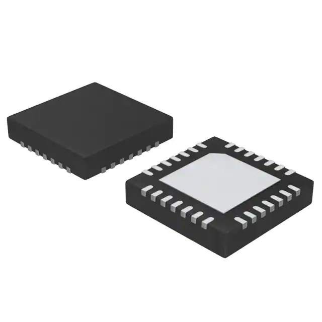
- Part No.:
- ATA5278-PKQI
- Manufacturer:
- Microchip Technology
- Category:
- RFID, RF Access, Monitoring ICs
- Package:
- 28-VQFN Exposed Pad
- Datasheet:
-
 ATA5278-PKQI.pdf
- Description:
- IC PEPS/TPMS 100-150KHZ 28QFN
- Quantity:
- Payment:

- Shipping:

Inventory:1,307
Please send an inquiry. Send us your inquiry, and we will respond immediately.
Product details
Overview
ATA5278-PKQI from Microchip Technology is an integrated BCDMOS LF antenna driver IC designed for Passive Entry/Go (PEG) car access systems. It delivers up to 1 A peak current to drive magnetic LF antenna coils, supports ASK/PSK modulation at 100–150 kHz carrier frequencies, operates from 7.5 V to 16 V battery input, and features SPI interface up to 1 Mbit/s for microcontroller control in automotive keyless entry applications.
For engineers reviewing the ATA5278-PKQI datasheet, ATA5278-PKQI pinout, ATA5278-PKQI application, or ATA5278-PKQI equivalent, this page provides verified technical context, validated pin functions, confirmed LF modulation timing behavior, real-world automotive operating conditions (–40°C to +105°C), and precise alternative part comparisons - all derived from Microchip's official ATA5278 documentation.
Technical Context
The ATA5278-PKQI integrates a half-bridge LF driver stage with boost converter, programmable coil current regulation (16-step), and dual-mode modulation (ASK/PSK). Its internal oscillator supports ceramic resonators or external clock sources, enabling fast oscillation build-up via Quick Start Control (QSC) for sub-100 µs startup with ceramic devices.
It implements a 192-bit FIFO data buffer decoupled from SPI timing, allowing microcontrollers to offload LF transmission while handling other tasks. The driver stage includes overtemperature, overcurrent (SH/SL/CH), open-load, and fault memory diagnostics - all accessible via SPI status register and cleared by dedicated command.
Key Specifications
| Parameter | Value and Actual Design Meaning |
|---|---|
| Carrier Frequency | 100–150 kHz - matches LF band for passive key fob communication and tire pressure sensor excitation. |
| LF Baud Rate | 1–4 kbaud - selectable via BR1/BR0 bits; defines logical bit period from 256 µs (4 kbaud) to 1024 µs (1 kbaud). |
| Peak Output Current | 1 A - delivered to antenna coil via DRV1 output, enabling sufficient magnetic field strength for >2 m PEG range. |
| SPI Speed | Up to 1 Mbit/s - enables rapid loading of up to 96 logical bits (192 half-bits) into internal buffer without CPU blocking. |
| Supply Voltage Range | 7.5 V to 16 V direct battery input - supports 12 V automotive systems; tolerates load dump up to 45 V on VBATT. |
| Operating Temperature | –40°C to +105°C - qualified for under-hood and door module mounting locations in automotive environments. |
| Modulation Modes | ASK and 180° PSK - selected via NASK_PSK bit; PSK requires external QSC-controlled loop switch above 2 kbaud. |
Pinout & Package
ATA5278-PKQI is housed in a 28-pin QFN package (5 mm × 5 mm, 0.5 mm pitch) with exposed thermal pad. Pin functions are validated per Microchip datasheet 4832D–RKE–12/07.
| Pin/Terminal | Circuit Role | Design Meaning |
|---|---|---|
| DRV1 | Antenna driver stage output | Half-bridge high-side output driving LF antenna coil; rated for 1 A peak current. |
| VDS | Driver voltage supply input | Input for regulated high-voltage supply to driver stage; derived from boost converter. |
| QSC | QSC transistor-gate driver-stage output | Drives external MOSFET gate to synchronize antenna current zero-crossing for fast PSK/ASK field decay. |
| VSHUNT | Antenna current-shunt resistor connection | Connects to shunt resistor for real-time current sensing and overcurrent protection (CH fault detection). |
| S_CS / S_CLK / S_DI / S_DO | SPI interface signals | Standard 4-wire slave-mode SPI: chip select, clock (≤1 MHz), data in, tristate data out. |
| MODACTIVE | Modulator status pin output | Active-high signal indicating LF transmission in progress; usable for system-level synchronization. |
| NRES | Reset input (inverted) | Asynchronous active-low reset; forces power-on-reset state, clearing configuration and faults. |
| OSCI / OSCO | Oscillator input/output | Supports ceramic resonator (typ. 1–4 MHz) or external clock source; internal oscillator enables autonomous LF timing. |
Key Features
| Feature | Design Value |
|---|---|
| Internal 192-bit FIFO data buffer | Decouples high-speed SPI writes from low-speed LF transmission, enabling concurrent MCU operation during 1–4 kbaud modulation. |
| Programmable coil current (16 steps) | Allows precise field strength tuning across vehicle platforms and antenna geometries without hardware changes. |
| Quick Start Control (QSC) | Generates zero-crossing-synchronized gate drive for external MOSFET, reducing LF field rise/fall time to enable reliable 4 kbaud PSK. |
| Integrated diagnosis & protection | Detects and latches overtemperature (OT), overcurrent (SH/SL/CH), open load (OL), and illegal commands - all readable via SPI status register. |
| Load dump protection (45 V) | Withstands automotive transients on VBATT without external TVS, simplifying front-end design for 12 V battery systems. |
Applications
| Hands-free Car Access (Passive Entry/Go) | Tire Pressure Measurement |
|---|---|
|
Use Scenario: Vehicle detects authorized key fob within ~2 m and unlocks doors automatically upon approach. IC Role / Device Role / Timing Role: ATA5278-PKQI generates modulated 125 kHz LF field to energize and communicate with fob transponder using ASK/PSK. Use Value: Enables fast, secure bidirectional challenge-response authentication with <100 µs oscillator startup and programmable field strength for consistent range. |
Use Scenario: TPMS sensor inside tire wakes on LF interrogation and transmits pressure/temperature data via UHF backchannel. IC Role / Device Role / Timing Role: ATA5278-PKQI drives LF antenna coil to send activation burst and command stream to sensor's receiver IC. Use Value: Supports 4 kbaud PSK mode with QSC for rapid sensor wake-up and command delivery, minimizing battery drain in sealed sensor modules. |
| Home Access Control | Care Watch Systems |
|
Use Scenario: Secure residential gate or door lock responds to authenticated wearable or fob without physical contact. IC Role / Device Role / Timing Role: ATA5278-PKQI acts as LF transmitter in wall-mounted or embedded reader unit, modulating data at 2 kbaud ASK. Use Value: Operates reliably from 7.5–16 V input and –40°C to +105°C ambient, supporting outdoor-rated enclosures and long-term deployment. |
Use Scenario: Wearable medical alert device uses LF field to trigger emergency beacon or verify proximity to caregiver unit. IC Role / Device Role / Timing Role: ATA5278-PKQI drives compact planar antenna to transmit short identification bursts at 1 kbaud for low-power operation. Use Value: Power-down mode draws minimal current; internal 5 V regulator and VIF interface support mixed-voltage MCU integration (3.3 V/5 V logic). |
Equivalent & Alternatives
The following parts are listed as comparable options for similar LF antenna driver applications.
| Alternative Part | Technical Difference | Application Difference | Selection Advice |
|---|---|---|---|
| ATA5782-PKQI | Higher integration: includes integrated 32-bit MCU core and AES encryption engine; same QFN28 package and pin-compatible DRV1/QSC/VSHUNT interface. | Targets secure PEG systems requiring on-chip cryptographic processing; not drop-in for pure driver-only designs. | Select ATA5782-PKQI only when firmware-based security and protocol stack execution are required alongside LF driving. |
| TDK IAM-85022 | Standalone LF transmitter IC with fixed 125 kHz carrier; no SPI interface - configured via I²C; max 500 mA output; no QSC or PSK support. | Suitable for cost-sensitive, low-data-rate applications like basic immobilizer antennas where ASK-only and lower current suffice. | Choose IAM-85022 for simplified designs lacking MCU resources for SPI control or needing lower BOM cost without PSK/QSC capability. |
Compared with ATA5278-PKQI, ATA5782-PKQI adds embedded security processing but increases firmware complexity, while TDK IAM-85022 reduces integration and modulation flexibility to achieve lower unit cost - making ATA5278-PKQI the optimal balance of programmability, diagnostic depth, and automotive-grade robustness for mid-tier PEG systems.
Availability
ATA5278-PKQI is available at Aetrix Electronics and suitable for hands-free car access, tire pressure measurement, home access control, and care watch systems requiring stable component supply, automotive qualification, and long lifecycle support.
Supply support for ATA5278-PKQI includes scheduled delivery planning, volume procurement assistance, BOM continuity management, traceable sourcing, and lifecycle availability coordination for OEM customers, industrial embedded developers, connected-device designers, and electronics production programs.
Manufacturer
Microchip Technology is a global semiconductor manufacturer specializing in microcontrollers, analog, and interface solutions, with deep expertise in automotive and secure embedded systems.
The ATA5278-PKQI belongs to Microchip's RKE (Remote Keyless Entry) antenna driver product line, engineered specifically for high-reliability, low-power LF transmission in automotive passive entry and industrial proximity sensing applications.
FAQ
What is the maximum LF data rate supported by the ATA5278-PKQI?
The ATA5278-PKQI supports LF baud rates of 1 kbaud, 2 kbaud, 3 kbaud, and 4 kbaud - selectable via BR1/BR0 bits in Configuration Register 2. At 4 kbaud, each logical bit has a 256 µs period, enabling fast key fob authentication. PSK mode above 2 kbaud requires use of the QSC pin to drive an external antenna loop switch for reliable phase transitions.
Does the ATA5278-PKQI require an external crystal or can it operate with a ceramic resonator?
Yes, the ATA5278-PKQI can operate with either a ceramic resonator or an external clock source - no crystal is required. Its integrated oscillator circuitry is optimized for ceramic devices (typ. 1–4 MHz), achieving oscillation build-up in under 100 µs. External clock inputs are accepted on the OSCI pin, and CLKO provides buffered output for system clock distribution.
How does the ATA5278-PKQI handle fault conditions such as overtemperature or overcurrent?
The ATA5278-PKQI continuously monitors temperature, antenna current (via VSHUNT), driver outputs, and load conditions. Detected faults - including OT (overtemperature), SH/SL/CH (overcurrent), OL (open load), and IC (illegal command) - are latched in the status register and disable power stages until cleared via SPI Command 2 (fault memory reset) or NRES assertion. This ensures fail-safe operation in automotive environments.
Can the ATA5278-PKQI drive multiple antenna coils simultaneously?
No, the ATA5278-PKQI is designed to drive a single LF antenna coil via its DRV1 output. While it provides three low-side coil connections (VL1/VL2/VL3) for boost converter topology, the high-side driver output is singular. Multi-coil systems require separate ATA5278-PKQI units or higher-channel alternatives like the ATA5782-PKQI with dual-driver variants.
What is the purpose of the MODACTIVE pin on the ATA5278-PKQI?
The MODACTIVE pin on the ATA5278-PKQI is an active-high open-drain output that signals when LF data transmission is actively occurring - asserted during modulation regardless of half-bit value (0 or 1). It enables external synchronization (e.g., triggering UHF response or logging transmission windows) and confirms real-time modulator activity independent of SPI bus traffic.
ATA5278-PKQI Specifications
- Product attributes
- Attribute value
- Manufacturer:
- Microchip Technology
- Series:
- -
- Package/Case:
- 28-VQFN Exposed Pad
- Packaging:
- Tape & Reel (TR)
- Product Status:
- Obsolete
- Type:
- Passive Entry/Start, TPMS
- Frequency:
- 100kHz ~ 150kHz
- Standards:
- -
- Interface:
- SPI
- Voltage - Supply:
- 7.5V ~ 16V
- Operating Temperature:
- -40°C ~ 105°C
- Grade:
- -
- Qualification:
- -
- Mounting Type:
- Surface Mount
- Supplier Device Package:
- 28-QFN (7x7)
ATA5278-PKQI FAQ
1.How can I place an order for ATA5278-PKQI through Aetrix?
Please submit a Request for Quotation (RFQ) for ATA5278-PKQI on Aetrix. Our sales agent will provide a competitive quotation and guide you through the order confirmation once you accept the terms.
2.Are the price and stock information for ATA5278-PKQI reliable?
The price and inventory of ATA5278-PKQI are updated periodically and may fluctuate due to market conditions. Stock and pricing data are typically refreshed every 24 hours. Quotation validity for ATA5278-PKQI is usually 5 days.
3.What payment methods are accepted for ATA5278-PKQI?
We accept Wire Transfer, PayPal, Credit Card, Western Union, MoneyGram, and Escrow for ATA5278-PKQI transactions.
Note: Certain payment methods may incur a processing fee.
4.How is shipping managed for ATA5278-PKQI?
ATA5278-PKQI orders can be shipped via leading logistics carriers, including DHL, UPS, FedEx, TNT, or Registered Mail.
Once your ATA5278-PKQI order is processed, you will receive an email with the shipment details and tracking number.
Note: Tracking information may take up to 24 hours to appear. Express delivery typically takes 3–5 business days.
5.How can I obtain technical support or documentation for ATA5278-PKQI?
For technical support, including ATA5278-PKQI datasheets, pinout diagrams, or application guidance, please contact our engineering support team. They can provide detailed documentation and assistance for your ATA5278-PKQI requirements.
6.How does Aetrix verify that ATA5278-PKQI is sourced from the original manufacturer or authorized distributors?
All ATA5278-PKQI products on Aetrix are procured from qualified distributors and authorized channels. Our dedicated quality assurance team conducts strict verification, including traceability checks and, if necessary, third-party testing. This ensures that ATA5278-PKQI meets industry standards.
7.What is the process for return or replacement of ATA5278-PKQI?
All ATA5278-PKQI units undergo pre-shipment inspection (PSI). If there is an issue with ATA5278-PKQI, returns or replacements are accepted under the following conditions:
1.Quantity discrepancies, incorrect items, or visible external defects (such as breakage or corrosion), acknowledged by Aetrix.
2.The issue is reported within 90 days of delivery.
3.The ATA5278-PKQI part is unused and in its original packaging.
Return procedure for ATA5278-PKQI:
1.Submit a request within 90 days.
2.Obtain a Return Material Authorization (RMA) from Aetrix.
ATA5278-PKQI Tags

-
SL2S2602FTBX
NXP Semiconductors

-
ST25DV04K-IER6S3
STMicroelectronics

-
ST25DV04K-IER6C3
STMicroelectronics
-
LXMSJZNCMD-217
Murata Electronics

-
NT3H2111W0FTTJ
NXP Semiconductors

-
NT3H2111W0FHKH
NXP Semiconductors

-
M24LR04E-RMC6T/2
STMicroelectronics
-
ST25DV04KC-JF6D3
STMicroelectronics

-
ST25DV64KC-IE6S3
STMicroelectronics

-
ST25DV64K-IER6T3
STMicroelectronics
-
NT3H2211W0FTTJ
NXP Semiconductors
-
NT3H2211W0FHKH
NXP Semiconductors
Tech Hub

TTL and CMOS logic families differ in thresholds, loading, output drive, power and timing. This engineering guide compares 74HC and 74HCT, calculates noise margins and checks 3.3 V/5 V compatibility.

A practical engineering guide to 3.3V and 5V logic compatibility, input thresholds, resistor dividers, translator ICs, MOSFET level shifting, I2C pull-ups, timing limits and power-sequencing risks.

The 74HC595 uses push-pull logic outputs, while the TPIC6B595 uses 50 V open-drain DMOS sinks for higher-power loads. This guide compares timing, current limits, 3.3 V interfacing, load wiring, thermal…

The 74HC595 converts serial data into eight stable parallel outputs. This guide covers pin functions, shift and storage timing, OE and MR behavior, drive-current limits, cascading, voltage compatibilit…

A technical comparison of level-sensitive latches and edge-triggered flip-flops, covering timing windows, setup and hold limits, master–slave operation, time borrowing, race-through, HDL inference and…

A D latch stores one bit while Enable controls when data can pass. This reference covers gate-level operation, truth tables, transparency, setup and hold timing, LE versus OE, common ICs and practical …

An SR latch stores one bit through cross-coupled feedback. This engineering reference covers NOR and NAND implementations, truth tables, forbidden-state recovery, gated operation, switch debouncing, fa…

Latch circuits retain one bit through feedback. This technical reference covers SR and D latches, truth tables, transparency, timing limits, latch-versus-flip-flop behavior, applications and common log…

An engineering guide to LED driver operation, constant-current and constant-voltage outputs, linear and switching topologies, dimming, IC selection, calculations, replacement compatibility, and fault c…

Operational amplifier guide covering op amp basics, feedback, ideal vs real op amps, common configurations, buffer circuits, offset, bias current, gain-bandwidth, slew rate, rail-to-rail limits and sel…


