
 My Inquiry
 My Account


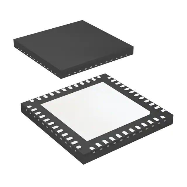
Microchip Technology ATA5279C-PLQW
- Part No.:
- ATA5279C-PLQW
- Manufacturer:
- Microchip Technology
- Category:
- RFID, RF Access, Monitoring ICs
- Package:
- 48-VFQFN Exposed Pad
- Datasheet:
-
 ATA5279C-PLQW.pdf
- Description:
- IC PASS ENTRY 125KHZ 48VQFN
- Quantity:
- Payment:

- Shipping:

Inventory:1,815
Please send an inquiry. Send us your inquiry, and we will respond immediately.
Product details
Overview
ATA5279C-PLQW from Microchip Technology (formerly Atmel) is a six-channel low-frequency antenna driver IC for passive entry/go (PEG) systems. It drives up to six series-resonant LF coils with peak currents of 1A (channels 1–3) and 700mA (channels 4–6), supports Manchester-coded OOK modulation up to 5.7 kbit/s, delivers sinusoidal-like output for superior EMC, and operates in QFN48 (7 mm × 7 mm) package for automotive key fob wake-up and initialization.
For engineers reviewing the ATA5279C-PLQW datasheet, ATA5279C-PLQW pinout, ATA5279C-PLQW application, or ATA5279C-PLQW equivalent, this page provides verified technical context, SPI-controlled current regulation (20 steps), coil diagnosis capability, thermal/electrical protection, and LF data buffering - all critical for RKE/PEPS system design and BOM validation.
Technical Context
The ATA5279C-PLQW integrates three independent boost-converter-supplied driver groups (VDS1–VDS3), each powering two channels with Darlington-configured N-channel DMOS stages optimized for low harmonic distortion. Its sine wave generator uses CINT-based amplitude control and zero-cross detection for precise current regulation via external shunt sensing (VSHS).
Operation modes include Power-down (≤1 µA), Idle (VDS/2 bias ready), Operating (active transmission), Shutdown (fault-triggered), and Diagnosis (programmable high-impedance test current sources on all AxP/AxN lines). SPI interface (POL=1/PHA=1 default) controls coil selection, current step (50–1000 mA), LF data buffering (128-bit FIFO), and fault register management.
Key Specifications
| Parameter | Value and Actual Design Meaning |
|---|---|
| LF Channels | 6 independent series-resonant coil drivers (3 high-current + 3 low-current groups) |
| Peak Output Current | 1 A (channels 1–3); 700 mA (channels 4–6) - stable across battery voltage variation |
| Data Modulation | On-off keying (OOK) with Manchester coding up to 5.7 kbit/s - ensures reliable key fob wakeup |
| Current Regulation Steps | 20 programmable steps (50–1000 mA) - enables precise RSSI-based field strength measurement |
| SPI Interface | 4-mode slave interface (max 2 Mbit/s @ 8 MHz OSCI) - enables microcontroller bus integration with minimal CPU load |
| Package | QFN48, 7 mm × 7 mm, 0.5 mm pitch - compact footprint for space-constrained automotive modules |
| Protection Features | Thermal shutdown, electrical overload, short-circuit detection, and automatic fault register logging - prevents damage during coil faults |
Pinout & Package
ATA5279C-PLQW is housed in a thermally enhanced QFN48 package (7 mm × 7 mm, 0.5 mm pitch) with exposed PGND heat slug for automotive-grade thermal dissipation. Pin functions are validated per Atmel 9125P-RKE-05/14 datasheet.
| Pin/Terminal | Circuit Role | Design Meaning |
|---|---|---|
| A1P–A6P | Coil positive drive outputs | High-side driver terminals for six LF antennas; grouped as HRL/LDL per channel |
| A1N1/A1N2–A6N1/A6N2 | Coil negative return line inputs | Dual-pin return path per coil; enables robust diagnostics and parasitic current suppression |
| VDS1–VDS3 | Driver supply inputs | Independent supply rails for three boost-converter-powered driver groups |
| VSHS | Shunt voltage sense input | Feeds coil current feedback to internal integrator for closed-loop current regulation |
| CINT | Integration capacitor connection | External capacitor sets sine wave amplitude and regulates boost converter output voltage |
| S_CS / S_CLK / MOSI / MISO | SPI interface signals | Full-duplex slave interface with chip select; supports 4 clock polarity/phase modes |
| IRQ / BCNT / MACT | Status and timing outputs | Interrupt request (fault), bit counter (modulation timing), and modulator active indicator |
| NRES | Active-low reset input | Hardware reset with ≥tNRES,min pulse - forces power-down mode entry |
Key Features
| Feature | Design Value |
|---|---|
| Multi-coil driver architecture | Simultaneous or sequential excitation of six LF antennas - enables 360° coverage in vehicle entry systems |
| Integrated diagnosis mode | Programmable high-impedance test current sources on all AxP/AxN pins - detects shorts-to-rail, open loads, and inter-coil faults without external hardware |
| LF data buffer | 128-bit FIFO between SPI and modulator - decouples microcontroller timing from real-time transmission requirements |
| Sinusoidal output waveform | Low-harmonic distortion signal generation - reduces EMI emissions and improves regulatory compliance in automotive environments |
| Boost converter control | On-demand DC-DC boost (enabled only during transmission) - extends battery life by avoiding continuous high-voltage rail generation |
| Thermal & electrical protection | Per-channel overtemperature and overcurrent shutdown with fault register storage - enables safe recovery and diagnostic logging in production systems |
Applications
| Passive Entry System (PES) | Remote Keyless Entry (RKE) |
|---|---|
Use Scenario: Vehicle door handle antenna array energized to detect proximity of authenticated key fob. IC Role / Device Role / Timing Role: ATA5279C-PLQW drives multiple LF coils sequentially to generate 125 kHz wake-up field; synchronizes with MCU via SPI for encrypted challenge-response handshake. Use Value: Enables seamless hands-free access with <100 ms latency and consistent field strength across all vehicle quadrants. | Use Scenario: Handheld key fob transmitter activated by button press to unlock doors remotely. IC Role / Device Role / Timing Role: ATA5279C-PLQW generates Manchester-coded 125 kHz carrier burst under MCU command; uses integrated LF buffer to minimize firmware overhead. Use Value: Achieves reliable 30+ meter range with ultra-low average current (<5 µA in power-down mode). |
| Smart Trunk Release | Vehicle Initialization Channel |
Use Scenario: Rear bumper-mounted LF antenna detects key fob presence to auto-open trunk when user approaches. IC Role / Device Role / Timing Role: ATA5279C-PLQW powers dedicated high-current coil (A1P/A1N) with 1 A peak current; leverages diagnosis mode to validate antenna integrity before activation. Use Value: Ensures fail-safe operation in wet/dirty conditions with automatic fault isolation and reporting. | Use Scenario: In-vehicle LF transceiver initializes secure communication with key fob prior to UWB or BLE handover. IC Role / Device Role / Timing Role: ATA5279C-PLQW acts as primary LF initialization channel - provides time-synchronized carrier and RSSI feedback for cryptographic key exchange. Use Value: Delivers deterministic timing and calibrated field strength (via 20-step current control) required for secure PEG authentication protocols. |
Equivalent & Alternatives
The following parts are listed as comparable options for similar LF antenna driver applications.
| Alternative Part | Technical Difference | Application Difference | Selection Advice |
|---|---|---|---|
| NXP PCF7962 | 5-channel LF driver; max 800 mA per channel; no integrated boost converter; requires external VDD regulation | Limited to 5 antennas; lacks diagnosis mode and CINT-based amplitude control | Choose for cost-sensitive RKE designs with ≤5 coils and existing regulated 5 V supply |
| Infineon TLE9183 | 6-channel driver with integrated LIN interface; supports PWM and analog current control; higher quiescent current (2.5 µA) | Designed for LIN-connected body controllers; lacks Manchester encoding support and RSSI calibration steps | Choose for LIN-based vehicle architectures requiring direct microcontroller integration without SPI translation layer |
Compared with PCF7962 and TLE9183, the ATA5279C-PLQW uniquely combines six-channel flexibility, on-chip boost conversion, 20-step RSSI-calibrated current control, and comprehensive coil diagnosis - making it optimal for next-generation PEG systems demanding full 360° coverage and field-deployable fault diagnostics.
Availability
ATA5279C-PLQW is available at Aetrix Electronics and suitable for automotive passive entry, remote keyless entry, smart trunk release, and vehicle initialization channel applications requiring stable component supply, long-term lifecycle support, and AEC-Q100-compliant sourcing.
Supply support for ATA5279C-PLQW includes scheduled delivery planning, volume procurement assistance, BOM continuity management, traceable sourcing, and lifecycle availability coordination for OEM customers, industrial embedded developers, connected-device designers, and electronics production programs.
Manufacturer
Microchip Technology acquired Atmel in 2016 and maintains full support for legacy Atmel automotive analog products including the ATA5279 family.
The ATA5279C product line was designed specifically for low-frequency antenna driving in passive entry and go (PEG) systems, emphasizing RF efficiency, diagnostic robustness, and integration with microcontroller-based security stacks.
FAQ
What is the maximum data rate supported by the ATA5279C-PLQW for LF communication?
The ATA5279C-PLQW supports on-off keying (OOK) modulation with Manchester coding at up to 5.7 kbit/s. This rate is confirmed in the official datasheet (9125P-RKE-05/14) and is sufficient for standard RKE challenge-response payloads and PEG initialization sequences. The ATA5279C-PLQW implements dedicated LF data buffering and timing logic to maintain signal integrity at this rate without MCU intervention.
Does the ATA5279C-PLQW require an external crystal or can it operate with an RC oscillator?
The ATA5279C-PLQW requires an external 8 MHz crystal connected between OSCI and OSCO pins for stable 125 kHz LF carrier generation and SPI timing. The datasheet specifies no internal RC oscillator option; oscillator accuracy directly impacts carrier frequency tolerance and Manchester decoding reliability. Using the recommended crystal ensures compliance with ISO 14230 and SAE J2735 LF timing requirements in the ATA5279C-PLQW application.
How does the ATA5279C-PLQW handle coil faults such as short circuits or open loads?
The ATA5279C-PLQW continuously monitors all six coil channels for shorts-to-rail and open loads using its integrated diagnosis mode and real-time current sensing. Upon detection, it enters shutdown mode, stores the fault in a register, asserts IRQ, and disables affected driver stages while preserving functionality of non-faulty channels. Recovery requires an SPI "Reset Fault Status" command - a behavior explicitly documented for the ATA5279C-PLQW in Section 3.6 of the datasheet.
Can the ATA5279C-PLQW drive coils with different impedances simultaneously?
Yes - the ATA5279C-PLQW supports two distinct coil impedance ranges: high-current channels (1–3) accept 10–30 Ω loads, while low-current channels (4–6) target 30–100 Ω. Driving mismatched coils may cause unstable current regulation or failed modulation, as stated in Section 3.2.1. The ATA5279C-PLQW's 20-step current control allows per-channel optimization, but impedance compatibility must be verified per channel group per the ATA5279C-PLQW datasheet guidelines.
What is the purpose of the CINT pin on the ATA5279C-PLQW, and what capacitor value is recommended?
The CINT pin connects to an external integration capacitor that sets both the sinusoidal output amplitude and the boost converter output voltage. Per Section 3.3 and Figure 3-3 of the ATA5279C-PLQW datasheet, a 100 nF X7R ceramic capacitor is specified for stable operation across temperature and voltage. Incorrect CINT values cause amplitude drift, poor current regulation, or boost converter instability - all directly impacting ATA5279C-PLQW RF performance and EMC behavior.
ATA5279C-PLQW Specifications
- Product attributes
- Attribute value
- Manufacturer:
- Microchip Technology
- Series:
- -
- Package/Case:
- 48-VFQFN Exposed Pad
- Packaging:
- Tape & Reel (TR)
- Product Status:
- Obsolete
- Type:
- Passive Entry/Start
- Frequency:
- 125kHz
- Standards:
- -
- Interface:
- SPI
- Voltage - Supply:
- 4.1V ~ 4.8V
- Operating Temperature:
- -40°C ~ 145°C
- Grade:
- -
- Qualification:
- -
- Mounting Type:
- Surface Mount
- Supplier Device Package:
- 48-VQFN (7x7)
ATA5279C-PLQW FAQ
1.How can I place an order for ATA5279C-PLQW through Aetrix?
Please submit a Request for Quotation (RFQ) for ATA5279C-PLQW on Aetrix. Our sales agent will provide a competitive quotation and guide you through the order confirmation once you accept the terms.
2.Are the price and stock information for ATA5279C-PLQW reliable?
The price and inventory of ATA5279C-PLQW are updated periodically and may fluctuate due to market conditions. Stock and pricing data are typically refreshed every 24 hours. Quotation validity for ATA5279C-PLQW is usually 5 days.
3.What payment methods are accepted for ATA5279C-PLQW?
We accept Wire Transfer, PayPal, Credit Card, Western Union, MoneyGram, and Escrow for ATA5279C-PLQW transactions.
Note: Certain payment methods may incur a processing fee.
4.How is shipping managed for ATA5279C-PLQW?
ATA5279C-PLQW orders can be shipped via leading logistics carriers, including DHL, UPS, FedEx, TNT, or Registered Mail.
Once your ATA5279C-PLQW order is processed, you will receive an email with the shipment details and tracking number.
Note: Tracking information may take up to 24 hours to appear. Express delivery typically takes 3–5 business days.
5.How can I obtain technical support or documentation for ATA5279C-PLQW?
For technical support, including ATA5279C-PLQW datasheets, pinout diagrams, or application guidance, please contact our engineering support team. They can provide detailed documentation and assistance for your ATA5279C-PLQW requirements.
6.How does Aetrix verify that ATA5279C-PLQW is sourced from the original manufacturer or authorized distributors?
All ATA5279C-PLQW products on Aetrix are procured from qualified distributors and authorized channels. Our dedicated quality assurance team conducts strict verification, including traceability checks and, if necessary, third-party testing. This ensures that ATA5279C-PLQW meets industry standards.
7.What is the process for return or replacement of ATA5279C-PLQW?
All ATA5279C-PLQW units undergo pre-shipment inspection (PSI). If there is an issue with ATA5279C-PLQW, returns or replacements are accepted under the following conditions:
1.Quantity discrepancies, incorrect items, or visible external defects (such as breakage or corrosion), acknowledged by Aetrix.
2.The issue is reported within 90 days of delivery.
3.The ATA5279C-PLQW part is unused and in its original packaging.
Return procedure for ATA5279C-PLQW:
1.Submit a request within 90 days.
2.Obtain a Return Material Authorization (RMA) from Aetrix.
ATA5279C-PLQW Tags

-
SL2S2602FTBX
NXP Semiconductors

-
ST25DV04K-IER6S3
STMicroelectronics

-
ST25DV04K-IER6C3
STMicroelectronics
-
LXMSJZNCMD-217
Murata Electronics

-
NT3H2111W0FTTJ
NXP Semiconductors

-
NT3H2111W0FHKH
NXP Semiconductors

-
M24LR04E-RMC6T/2
STMicroelectronics
-
ST25DV04KC-JF6D3
STMicroelectronics

-
ST25DV64KC-IE6S3
STMicroelectronics

-
ST25DV64K-IER6T3
STMicroelectronics
-
NT3H2211W0FTTJ
NXP Semiconductors
-
NT3H2211W0FHKH
NXP Semiconductors
Tech Hub

TTL and CMOS logic families differ in thresholds, loading, output drive, power and timing. This engineering guide compares 74HC and 74HCT, calculates noise margins and checks 3.3 V/5 V compatibility.

A practical engineering guide to 3.3V and 5V logic compatibility, input thresholds, resistor dividers, translator ICs, MOSFET level shifting, I2C pull-ups, timing limits and power-sequencing risks.

The 74HC595 uses push-pull logic outputs, while the TPIC6B595 uses 50 V open-drain DMOS sinks for higher-power loads. This guide compares timing, current limits, 3.3 V interfacing, load wiring, thermal…

The 74HC595 converts serial data into eight stable parallel outputs. This guide covers pin functions, shift and storage timing, OE and MR behavior, drive-current limits, cascading, voltage compatibilit…

A technical comparison of level-sensitive latches and edge-triggered flip-flops, covering timing windows, setup and hold limits, master–slave operation, time borrowing, race-through, HDL inference and…

A D latch stores one bit while Enable controls when data can pass. This reference covers gate-level operation, truth tables, transparency, setup and hold timing, LE versus OE, common ICs and practical …

An SR latch stores one bit through cross-coupled feedback. This engineering reference covers NOR and NAND implementations, truth tables, forbidden-state recovery, gated operation, switch debouncing, fa…

Latch circuits retain one bit through feedback. This technical reference covers SR and D latches, truth tables, transparency, timing limits, latch-versus-flip-flop behavior, applications and common log…

An engineering guide to LED driver operation, constant-current and constant-voltage outputs, linear and switching topologies, dimming, IC selection, calculations, replacement compatibility, and fault c…

Operational amplifier guide covering op amp basics, feedback, ideal vs real op amps, common configurations, buffer circuits, offset, bias current, gain-bandwidth, slew rate, rail-to-rail limits and sel…


