
 My Inquiry
 My Account


Microchip Technology ATA5279C-WGQW
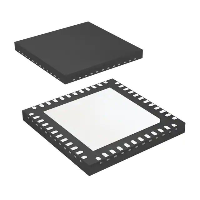
- Part No.:
- ATA5279C-WGQW
- Manufacturer:
- Microchip Technology
- Category:
- RFID, RF Access, Monitoring ICs
- Package:
- 48-VFQFN Exposed Pad
- Datasheet:
-
 ATA5279C-WGQW.pdf
- Description:
- IC PASS ENTRY 125KHZ 48VQFN
- Quantity:
- Payment:

- Shipping:

Inventory:3,424
Please send an inquiry. Send us your inquiry, and we will respond immediately.
Product details
Overview
ATA5279C-WGQW from Microchip Technology (formerly Atmel) is a 6-channel low-frequency antenna driver IC designed for passive entry/go (PEG) systems. It drives up to six series-resonant LF coils with peak currents of 1A (channels 1–3) and 700mA (channels 4–6), supports Manchester-coded OOK modulation up to 5.7 kbit/s, delivers sinusoidal-like output for superior EMC, and operates in QFN48 (7 mm × 7 mm) package.
For engineers reviewing the ATA5279C-WGQW datasheet, ATA5279C-WGQW pinout, ATA5279C-WGQW application, or ATA5279C-WGQW equivalent, this page provides verified technical context, SPI-controlled current regulation (20-step RSSI), thermal/electrical protection, LF data buffering, and coil diagnosis capability - all critical for automotive keyless entry system design and validation.
Technical Context
The ATA5279C-WGQW integrates three independent boost-converter-supplied driver groups (VDS1–VDS3), each powering two complementary N-channel DMOS stages per coil channel. Its sine wave generator uses CINT-based amplitude control and zero-cross detection for precise current regulation, with internal shunt sensing (VSHS) and sample-and-hold circuitry enabling closed-loop coil current control across 20 programmable steps.
Operation modes include Power-down (≤1 µA), Idle (VDS/2 bias ready), Operating (active transmission), Shutdown (fault-protected high-Z), and Diagnosis (programmable high-ohmic test sources on AxP/AxN). SPI interface (POL=1/PHA=1 default, up to 2 Mbit/s @ 8 MHz OSCI) controls all functions, while LF data buffer (128-bit FIFO) decouples microcontroller timing from real-time modulation demands.
Key Specifications
| Parameter | Value and Actual Design Meaning |
|---|---|
| Driver Channels | 6 independent LF coil drivers, grouped as high-current (Ch1–3, 1A peak) and low-current (Ch4–6, 700mA peak) |
| Modulation | On-off keying (OOK) with Manchester coding, max 5.7 kbit/s - enables robust 125 kHz wake-up frame transmission |
| Current Regulation | 20-step SPI-programmable regulation (50–1000 mA), with step-specific coil group restrictions for stable operation |
| Output Signal | Sinusoidal-like waveform with low harmonic distortion - reduces EMI emissions and improves antenna coupling efficiency |
| Supply Architecture | Three independent VDS-supplied driver groups; integrated boost converter (125 kHz switching) enabled only during transmission |
| Protection Features | Thermal shutdown, overcurrent detection, short-circuit fault detection on all AxP/AxN lines, automatic shutdown mode entry |
| Interface | SPI slave (4-mode configurable), 8 MHz max OSCI input → 2 Mbit/s max S_CLK, with IRQ, BCNT, and MACT status outputs |
Pinout & Package
ATA5279C-WGQW is housed in a thermally enhanced QFN48 package (7 mm × 7 mm, 0.5 mm pitch) with exposed PGND heat slug. Pin assignment follows standard Atmel/Microchip QFN48 layout for ATA5279 family, with dedicated groups for coil drive (AxP/AxN), driver supply (VDS1–VDS3), ground (PGND/RGND/AGND1–3), SPI (MISO/MOSI/S_CLK/S_CS), and diagnostic/control signals (IRQ/NRES/MACT/BCNT).
| Pin/Terminal | Circuit Role | Design Meaning |
|---|---|---|
| A1P–A6P | Coil positive drive outputs | HDL/LDL pins delivering regulated sinusoidal current to coil terminals; polarity defines high-side drive path |
| A1N1/A1N2–A6N1/A6N2 | Coil negative return line inputs | HRL/LRL dual-pin configuration per coil - enables differential fault detection and return-path current sensing |
| VDS1–VDS3 | Driver stage supply inputs | Independent power rails per driver group; accept boosted or direct battery voltage; enable selective coil activation |
| VSHS | Shunt sense voltage input | Connects to external current-sense resistor (typically 1 Ω); feeds zero-cross and peak-sample circuitry for closed-loop regulation |
| CINT | Integration capacitor node | External capacitor sets sine-wave amplitude and regulates boost converter output voltage; internal integrator reference point |
| S_CS / S_CLK / MOSI / MISO | SPI interface signals | Full-duplex slave interface with chip-select–gated output; supports 4 SPI modes; VIF-referenced logic (1.8–5.5 V) |
| IRQ / NRES / MACT / BCNT | Status and control outputs | IRQ signals fault or transmission end; NRES resets chip; MACT indicates active modulation; BCNT outputs bit counter |
Key Features
| Feature | Design Value |
|---|---|
| 6-channel LF antenna driving | Enables full-vehicle PEG coverage (e.g., front/rear doors, trunk, under-hood) without external multiplexers or discrete drivers |
| Programmable current regulation (20 steps) | Supports field-strength measurement (RSSI) and adaptive coil tuning - critical for varying antenna geometries and environmental conditions |
| Integrated diagnosis mode | Per-coil AxP/AxN line testing via programmable current sources and comparators - detects shorts-to-rail, opens, and inter-coil faults |
| LF data buffer (128-bit FIFO) | Offloads microcontroller during transmission bursts; allows background command queuing without real-time SPI timing constraints |
| Thermal and electrical protection | Automatic shutdown on overtemperature, coil short, or excessive current - prevents damage during fault conditions or miswiring |
| Low-power power-down mode | Typical 0.5 µA quiescent current - extends battery life in key fob or gate controller applications where IC remains always-on |
Applications
| Automotive Passive Entry/Go (PEG) | Vehicle Key Fob Wake-up System |
|---|---|
|
Use Scenario: Integrated into vehicle body control module (BCM) to energize LF antennas around door handles, trunk lid, and ignition area. IC Role / Device Role / Timing Role: Primary LF coil driver generating 125 kHz wake-up fields; synchronizes with RF receive path for secure handshake. Use Value: Enables seamless "walk-up-and-enter" functionality with sub-200 ms latency and immunity to ambient RF noise due to sinusoidal waveform and closed-loop current control. |
Use Scenario: Embedded in OEM key fobs to detect proximity via LF field strength (RSSI) before initiating encrypted RF challenge-response. IC Role / Device Role / Timing Role: Receives LF wake-up signal and measures field strength using 20-step current regulation; triggers secure authentication sequence. Use Value: Accurate RSSI enables distance-based access control (e.g., unlock at 1.5 m, start engine at 0.5 m), reducing false triggers and improving security. |
| Smart Access Control Panel | Industrial Equipment Authorization System |
|
Use Scenario: Mounted in secure entry gates or elevator lobbies to provide hands-free access for authorized personnel carrying LF-enabled credentials. IC Role / Device Role / Timing Role: Drives multiple directional LF antennas to cover wide entry zones; uses diagnosis mode for periodic coil integrity verification. Use Value: Reduces maintenance downtime by detecting broken or shorted antenna wiring before system failure - critical for unattended access points. |
Use Scenario: Used in factory floor machinery to authenticate operator credentials before enabling hazardous motion sequences. IC Role / Device Role / Timing Role: Provides fail-safe LF wake-up and coil health monitoring; enters shutdown mode on fault to prevent unsafe activation. Use Value: Meets ISO 13849 PLd safety requirements via hardware-enforced fault detection and automatic deactivation - no software-only reliance. |
Equivalent & Alternatives
The following parts are listed as comparable options for similar LF antenna driver applications.
| Alternative Part | Technical Difference | Application Difference | Selection Advice |
|---|---|---|---|
| NXP PCF7962 | 5-channel LF driver; max 800 mA/channel; no integrated boost converter; requires external DC-DC for >5.5 V operation | Limited to lower-power coil configurations; lacks built-in diagnosis mode and RSSI-capable current steps | Preferred when board space is constrained and coil loads are uniform and low-impedance; lower BOM cost but higher system design effort |
| Infineon TLE9183QX | 6-channel driver with integrated LIN transceiver; 1.2 A peak/channel; supports PWM and analog current control; larger HTQFP48 package (9×9 mm) | Targets LIN-connected body electronics; includes communication stack support not present in ATA5279C-WGQW | Selected when co-location with LIN bus is required and higher peak current or automotive ASIL-B compliance is mandated |
Compared with PCF7962 and TLE9183QX, ATA5279C-WGQW uniquely balances high integration (boost converter, diagnosis, 20-step RSSI), compact QFN48 footprint, and automotive-grade protection - making it optimal for cost-sensitive, space-constrained PEG modules requiring autonomous coil health management.
Availability
ATA5279C-WGQW is available at Aetrix Electronics and suitable for automotive passive entry systems, smart access control panels, and industrial authorization devices requiring stable component supply, long-term lifecycle support, and AEC-Q100 qualified performance.
Supply support for ATA5279C-WGQW includes scheduled delivery planning, volume procurement assistance, BOM continuity management, traceable sourcing, and lifecycle availability coordination for OEM customers, industrial embedded developers, connected-device designers, and electronics production programs.
Manufacturer
Microchip Technology acquired Atmel in 2016 and maintains full support for the ATA5279 family, including datasheets, application notes, and validation tools for automotive and industrial LF systems.
The ATA5279C product line was engineered specifically for ultra-low-power, multi-antenna passive entry applications - emphasizing EMC robustness, coil-level diagnostics, and seamless microcontroller integration via SPI and hardware status signaling.
FAQ
What is the maximum supported data rate for OOK modulation on the ATA5279C-WGQW?
The ATA5279C-WGQW supports on-off keying (OOK) modulation with Manchester coding at up to 5.7 kbit/s. This rate is validated for reliable 125 kHz LF wake-up frame transmission in automotive PEG systems. The modulation is implemented in hardware, with timing controlled by the internal oscillator and synchronized to the SPI-commanded transmission start. Higher rates are not supported due to bandwidth limitations of the integrated sine-wave generator and coil driver bandwidth.
Does the ATA5279C-WGQW require an external crystal or can it operate with a ceramic resonator?
The ATA5279C-WGQW requires an external 8 MHz crystal connected between OSCI and OSCO pins for stable 125 kHz LF carrier generation and accurate SPI timing. Ceramic resonators are not recommended - the datasheet specifies crystal load capacitance (12 pF) and frequency tolerance (±100 ppm) to ensure proper zero-cross detection, boost converter synchronization, and Manchester decoding fidelity. Using a resonator may cause timing drift and failed coil current regulation.
How does the diagnosis mode on the ATA5279C-WGQW detect a short between two coil positive lines (e.g., A1P and A2P)?
The ATA5279C-WGQW diagnosis mode detects inter-coil shorts by activating programmable current sources on individual AxP/AxN lines and reading back comparator outputs. For A1P–A2P short detection, the IC applies a high-side test current to A1P while monitoring A2P's voltage level; if both lines read identical logic states under opposing test conditions (e.g., one pulled high, one pulled low), a short is confirmed. This is executed via SPI commands Select Driver, Set Coil Current, and Get Driver Setup - no external test equipment required.
Can the ATA5279C-WGQW drive coils with impedances outside the specified range for its driver groups?
The ATA5279C-WGQW specifies distinct coil impedance ranges for high-current (Ch1–3) and low-current (Ch4–6) groups. Driving a coil outside its designated range - for example, applying a 750 mA current step to a low-current coil - may result in unstable current regulation, distorted output waveform, or failure to maintain Manchester timing. While the IC allows such configuration via SPI, the datasheet explicitly states full functionality (including stabilized current and guaranteed modulation) is not assured outside the defined ranges.
What is the role of the CINT pin on the ATA5279C-WGQW, and what capacitor value is recommended?
The CINT pin on the ATA5279C-WGQW connects to an external integration capacitor that sets the amplitude of the internal sine-wave generator and regulates the boost converter output voltage. A 100 nF X7R ceramic capacitor (±10 % tolerance, rated ≥16 V) is recommended per the datasheet. Incorrect CINT values cause amplitude instability, poor current regulation accuracy, and inconsistent boost startup - directly impacting RSSI repeatability and transmission range.
ATA5279C-WGQW Specifications
- Product attributes
- Attribute value
- Manufacturer:
- Microchip Technology
- Series:
- -
- Package/Case:
- 48-VFQFN Exposed Pad
- Packaging:
- Tape & Reel (TR)
- Product Status:
- Active
- Type:
- Passive Entry/Start
- Frequency:
- 125kHz
- Standards:
- -
- Interface:
- SPI
- Voltage - Supply:
- 4.1V ~ 4.8V
- Operating Temperature:
- -40°C ~ 145°C
- Grade:
- -
- Qualification:
- -
- Mounting Type:
- Surface Mount
- Supplier Device Package:
- 48-VQFN (7x7)
ATA5279C-WGQW FAQ
1.How can I place an order for ATA5279C-WGQW through Aetrix?
Please submit a Request for Quotation (RFQ) for ATA5279C-WGQW on Aetrix. Our sales agent will provide a competitive quotation and guide you through the order confirmation once you accept the terms.
2.Are the price and stock information for ATA5279C-WGQW reliable?
The price and inventory of ATA5279C-WGQW are updated periodically and may fluctuate due to market conditions. Stock and pricing data are typically refreshed every 24 hours. Quotation validity for ATA5279C-WGQW is usually 5 days.
3.What payment methods are accepted for ATA5279C-WGQW?
We accept Wire Transfer, PayPal, Credit Card, Western Union, MoneyGram, and Escrow for ATA5279C-WGQW transactions.
Note: Certain payment methods may incur a processing fee.
4.How is shipping managed for ATA5279C-WGQW?
ATA5279C-WGQW orders can be shipped via leading logistics carriers, including DHL, UPS, FedEx, TNT, or Registered Mail.
Once your ATA5279C-WGQW order is processed, you will receive an email with the shipment details and tracking number.
Note: Tracking information may take up to 24 hours to appear. Express delivery typically takes 3–5 business days.
5.How can I obtain technical support or documentation for ATA5279C-WGQW?
For technical support, including ATA5279C-WGQW datasheets, pinout diagrams, or application guidance, please contact our engineering support team. They can provide detailed documentation and assistance for your ATA5279C-WGQW requirements.
6.How does Aetrix verify that ATA5279C-WGQW is sourced from the original manufacturer or authorized distributors?
All ATA5279C-WGQW products on Aetrix are procured from qualified distributors and authorized channels. Our dedicated quality assurance team conducts strict verification, including traceability checks and, if necessary, third-party testing. This ensures that ATA5279C-WGQW meets industry standards.
7.What is the process for return or replacement of ATA5279C-WGQW?
All ATA5279C-WGQW units undergo pre-shipment inspection (PSI). If there is an issue with ATA5279C-WGQW, returns or replacements are accepted under the following conditions:
1.Quantity discrepancies, incorrect items, or visible external defects (such as breakage or corrosion), acknowledged by Aetrix.
2.The issue is reported within 90 days of delivery.
3.The ATA5279C-WGQW part is unused and in its original packaging.
Return procedure for ATA5279C-WGQW:
1.Submit a request within 90 days.
2.Obtain a Return Material Authorization (RMA) from Aetrix.
ATA5279C-WGQW Tags

-
SL2S2602FTBX
NXP Semiconductors

-
ST25DV04K-IER6S3
STMicroelectronics

-
ST25DV04K-IER6C3
STMicroelectronics
-
LXMSJZNCMD-217
Murata Electronics

-
NT3H2111W0FTTJ
NXP Semiconductors

-
NT3H2111W0FHKH
NXP Semiconductors

-
M24LR04E-RMC6T/2
STMicroelectronics
-
ST25DV04KC-JF6D3
STMicroelectronics

-
ST25DV64KC-IE6S3
STMicroelectronics

-
ST25DV64K-IER6T3
STMicroelectronics
-
NT3H2211W0FTTJ
NXP Semiconductors
-
NT3H2211W0FHKH
NXP Semiconductors
Tech Hub

TTL and CMOS logic families differ in thresholds, loading, output drive, power and timing. This engineering guide compares 74HC and 74HCT, calculates noise margins and checks 3.3 V/5 V compatibility.

A practical engineering guide to 3.3V and 5V logic compatibility, input thresholds, resistor dividers, translator ICs, MOSFET level shifting, I2C pull-ups, timing limits and power-sequencing risks.

The 74HC595 uses push-pull logic outputs, while the TPIC6B595 uses 50 V open-drain DMOS sinks for higher-power loads. This guide compares timing, current limits, 3.3 V interfacing, load wiring, thermal…

The 74HC595 converts serial data into eight stable parallel outputs. This guide covers pin functions, shift and storage timing, OE and MR behavior, drive-current limits, cascading, voltage compatibilit…

A technical comparison of level-sensitive latches and edge-triggered flip-flops, covering timing windows, setup and hold limits, master–slave operation, time borrowing, race-through, HDL inference and…

A D latch stores one bit while Enable controls when data can pass. This reference covers gate-level operation, truth tables, transparency, setup and hold timing, LE versus OE, common ICs and practical …

An SR latch stores one bit through cross-coupled feedback. This engineering reference covers NOR and NAND implementations, truth tables, forbidden-state recovery, gated operation, switch debouncing, fa…

Latch circuits retain one bit through feedback. This technical reference covers SR and D latches, truth tables, transparency, timing limits, latch-versus-flip-flop behavior, applications and common log…

An engineering guide to LED driver operation, constant-current and constant-voltage outputs, linear and switching topologies, dimming, IC selection, calculations, replacement compatibility, and fault c…

Operational amplifier guide covering op amp basics, feedback, ideal vs real op amps, common configurations, buffer circuits, offset, bias current, gain-bandwidth, slew rate, rail-to-rail limits and sel…


