
 My Inquiry
 My Account


Texas Instruments CF45538NSRG4
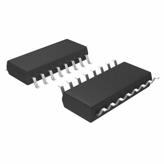
- Part No.:
- CF45538NSRG4
- Manufacturer:
- Texas Instruments
- Category:
- RFID, RF Access, Monitoring ICs
- Package:
- 16-SOIC (0.209", 5.30mm Width)
- Datasheet:
-
 CF45538NSRG4.pdf
- Description:
- IC RFID TRANSP 134.2KHZ 16SO
- Quantity:
- Payment:

- Shipping:

Inventory:2,568
Please send an inquiry. Send us your inquiry, and we will respond immediately.
Product details
Overview
CF45538NSRG4 from Texas Instruments is a CMOS-based RF-module IC designed for automotive TIRIS read-write systems. It integrates transmitter signal control logic, open-drain power drivers (TXHI/TXLO), and a fully digitized FSK demodulator with internal 17.1776 MHz oscillator. It operates from 4.5 V to 5.5 V across –40°C to +85°C and implements dual-mode operation (transmit/receive) via TXCT– pin control for contactless ID communication with remote TIRIS transponders.
For engineers reviewing the CF45538NSRG4 datasheet, CF45538NSRG4 pinout, CF45538NSRG4 application, or CF45538NSRG4 equivalent, this page delivers verified technical context, 16-pin SO package mapping, real-world timing constraints (e.g., 134.2 kHz transmit frequency, 132-cycle FSK discrimination threshold), and validated automotive-grade alternatives aligned with TIRIS protocol requirements.
Technical Context
The CF45538NSRG4 implements a fixed-frequency, two-mode RF modem architecture: in Sending Mode (TXCT– = L), it divides its 17.1776 MHz master clock by 128 to generate 134.2 kHz composite drive signals on TXHI/TXLO for antenna resonance; in Receiving Mode (TXCT– = H), it digitizes incoming FSK signals at A3OP using binary cycle-count discrimination against a fixed 132-clock threshold to output bit data on RXDT– and synchronized clocks on RXCK.
Its receiver path uses three cascaded CMOS inverters (A1–A3) for analog signal amplification prior to digital demodulation, with polarity-inverted RXDT– output (L = "1", H = "0") and automatic RXCK resynchronization triggered by 0→1 transitions in demodulated data - all without embedded protocol handling, error detection, or data formatting logic.
Key Specifications
| Parameter | Value and Actual Design Meaning |
|---|---|
| Operating Voltage | 4.5 V to 5.5 V - ensures compatibility with automotive 5 V supply rails and noise margin under load dump conditions. |
| Operating Temperature | –40°C to +85°C - qualified for under-hood and cabin-mounted automotive electronics per AEC-Q100 stress profiles. |
| Master Clock Frequency | 17.1776 MHz ±52.8 kHz - defines transmit carrier (134.2 kHz) and FSK discrimination accuracy; tolerance derived from fexc/128 and fL/fH alignment with TIRIS transponders. |
| Transmit Output | NCH/PCH open-drain (TXLO/TXHI) - drives external MOSFET antenna driver stage with bidirectional current capability up to ±20 mA. |
| FSK Discrimination Threshold | 132 master clock cycles - sets binary decision boundary between 123.2 kHz (bit "0") and 134.2 kHz (bit "1") at A3OP input. |
| RXDT– Polarity | Inverted vs. TIRIS standard - outputs L for "1", H for "0"; requires level inversion or controller logic adaptation in host system. |
| RXCK Timing Reference | Divided from A3OP signal by 16 - provides synchronous clock aligned to received bit groups, with automatic reset on 0→1 transitions to correct sync drift. |
Pinout & Package
CF45538NSRG4 is housed in a 16-pin Small Outline Package (SOP) with 1.27 mm pitch, 9.9–10.5 mm body length, and 7.4–8.2 mm body width per SCBU036 dimensional drawing.
| Pin/Terminal | Circuit Role | Design Meaning |
|---|---|---|
| A3OP | FSK signal digital demodulator input | Output of third CMOS inverter; feeds digitized FSK waveform directly to internal counter-based discriminator. |
| A3IN | FSK signal amplifier input | Input to third inverter stage; accepts externally amplified FSK signals when bypassing first two amplifiers. |
| TXLO | N-channel open-drain transmit output | Drives low-side MOSFET in LC antenna resonator; sinks up to 20 mA during transmit mode. |
| TXHI | P-channel open-drain transmit output | Drives high-side MOSFET in LC antenna resonator; sources up to 20 mA during transmit mode. |
| TXCT– | Transmit/Receive mode control input | Active-low signal: L = Transmit (TXHI/TXLO active), H = Receive (RXDT–/RXCK active, TX outputs disabled). |
| RXDT– | Demodulated bit data output | Inverted serial output: L = "1", H = "0"; requires external inversion or controller-level interpretation. |
| RXCK | Demodulated bit clock output | Synchronous clock aligned to RXDT– bit edges; resets on 0→1 transitions to maintain timing integrity. |
| OSCI/OSCO | 17.1776 MHz crystal oscillator interface | Connects to parallel-resonant crystal; defines all timing including transmit carrier and FSK discrimination accuracy. |
Key Features
| Feature | Design Value |
|---|---|
| Digitized FSK demodulation | Eliminates analog filters and tuning components; uses internal 17.1776 MHz clock counting for deterministic bit discrimination at A3OP. |
| Dual-mode transmit/receive control | Single-pin (TXCT–) switching enables time-division duplex operation without external mode logic or state machines. |
| Integrated 3-stage CMOS amplifier chain | Configurable gain and bandwidth via external bias resistors/capacitors on A1IN/A1OP through A3IN/A3OP pins. |
| Antenna driver outputs (TXHI/TXLO) | Open-drain NCH/PCH pair supports efficient push-pull driving of LC resonant antenna circuits at 134.2 kHz. |
| Auto-synchronized RXCK generation | 16× division from A3OP with dynamic reset on 0→1 transitions ensures robust clock/data alignment despite noise-induced sync loss. |
Applications
| Automotive Keyless Entry Transceiver | Vehicle Immobilizer Reader Module |
|---|---|
Use Scenario: Embedded in car door handle or pillar module to communicate with passive key fob transponders during approach or ignition sequence. IC Role / Device Role / Timing Role: Acts as physical-layer RF modem - generates 134.2 kHz excitation field, receives and digitizes FSK-encoded ID response, outputs synchronized bit stream to microcontroller. Use Value: Enables compact, low-cost reader design with no external demodulator or crystal tuning; meets ISO 11784/11785 carrier and modulation requirements for TIRIS-compatible systems. | Use Scenario: Mounted in steering column or ignition switch housing to authenticate transponder-equipped ignition keys before engine start. IC Role / Device Role / Timing Role: Provides secure, low-power RF link for challenge-response authentication; handles precise timing of 134.2 kHz carrier burst and FSK reply window per TIRIS protocol timing diagrams. Use Value: Delivers deterministic 132-cycle FSK discrimination and auto-resynchronized RXCK - critical for reliable ID decoding under EMI-rich engine bay conditions. |
| RFID-Based Tire Pressure Sensor Reader | Automotive Access Control Gateway |
Use Scenario: Integrated into TPMS diagnostic tool or vehicle service equipment to read tire-mounted TIRIS transponders during maintenance. IC Role / Device Role / Timing Role: Serves as handheld or benchtop RF interrogator - supplies regulated 134.2 kHz field, captures and decodes FSK-modulated pressure/temperature data packets. Use Value: Supports full TIRIS frame structure parsing via clean RXDT–/RXCK interface; eliminates need for external PLLs or analog front-end calibration. | Use Scenario: Deployed in vehicle gateway ECU to unify access credentials from multiple TIRIS-enabled devices (keys, fobs, smart cards) into CAN/LIN network. IC Role / Device Role / Timing Role: Functions as standardized TIRIS PHY layer - converts raw FSK bit streams into protocol-agnostic digital data for higher-layer security processing. Use Value: Provides deterministic timing (e.g., 56.3 ns master clock resolution) and polarity-aware RXDT– output - enabling deterministic firmware-level bit extraction without hardware adaptation. |
Equivalent & Alternatives
The following parts are listed as comparable options for similar RF transceiver applications.
| Alternative Part | Technical Difference | Application Difference | Selection Advice |
|---|---|---|---|
| RI-RFM-005A | Same 16-pin SO package and TIRIS protocol compliance, but lacks integrated oscillator - requires external 17.1776 MHz clock source on OSCO pin. | Used where board space allows discrete oscillator placement and tighter clock sourcing control is needed. | Select RI-RFM-005A only if external clock distribution improves system-level jitter performance or enables shared clocking with other modules. |
| RI-RFM-007A | Includes enhanced ESD protection (±8 kV HBM) and extended temperature range (–40°C to +105°C); identical pinout and functional behavior. | Targeted at under-hood applications exceeding 85°C ambient, such as engine control or transmission modules. | Choose RI-RFM-007A when operating environment exceeds +85°C or higher ESD immunity is mandated by OEM test plans. |
Compared with CF45538NSRG4, RI-RFM-005A trades integrated oscillator convenience for external clock flexibility, while RI-RFM-007A extends thermal and ESD robustness without altering interface or timing behavior - making CF45538NSRG4 optimal for cost-sensitive, cabin-mounted TIRIS readers requiring self-contained timing.
Availability
CF45538NSRG4 is available at Aetrix Electronics and suitable for automotive keyless entry systems, vehicle immobilizer modules, and TPMS diagnostic tools requiring stable component supply across long production lifecycles.
Supply support for CF45538NSRG4 includes scheduled delivery planning, volume procurement assistance, BOM continuity management, traceable sourcing, and lifecycle availability coordination for OEM customers, industrial embedded developers, connected-device designers, and electronics production programs.
Manufacturer
Texas Instruments is a global semiconductor leader specializing in analog, embedded processing, and connectivity solutions for automotive, industrial, and communications markets.
The CF45538NSRG4 belongs to TI's TIRIS RF-module product line, engineered specifically for contactless identification systems in automotive environments - emphasizing protocol-compliant 134.2 kHz carrier generation, digitized FSK demodulation, and robust operation across extended temperature ranges.
FAQ
What is the master clock frequency specification for CF45538NSRG4?
The CF45538NSRG4 uses an internal 17.1776 MHz master clock oscillator, with absolute frequency tolerance of ±52.8 kHz (±0.307%) to ensure proper alignment with TIRIS transponder excitation and FSK response frequencies. This value is specified in SCBU036 Section 7.2.2 and determines all timing parameters including transmit carrier (134.2 kHz) and FSK discrimination thresholds. The oscillator requires a parallel-resonant crystal connected between OSCI and OSCO pins.
How does CF45538NSRG4 handle FSK signal demodulation without analog components?
The CF45538NSRG4 performs fully digitized FSK demodulation by measuring the period of incoming signals at the A3OP pin using its internal 17.1776 MHz clock counter. A fixed threshold of 132 clock cycles discriminates between 123.2 kHz (bit "0") and 134.2 kHz (bit "1"), outputting inverted logic levels on RXDT–. This eliminates external filters, comparators, or PLLs - confirmed in SCBU036 Sections 6.3 and 8.2.
What is the function of the TPC pin on CF45538NSRG4?
The TPC (Transmit Power Control) pin on CF45538NSRG4 is an input with internal pull-up resistor that selects between high and low transmit power levels. When driven low, it reduces antenna drive strength to lower radiated emissions and extend battery life in portable readers - detailed in SCBU036 Section 5 (Pin #13) and Figure 6.2. No external components are required for basic operation.
Why is RXDT– polarity inverted relative to standard TIRIS RF-modules?
The RXDT– output of CF45538NSRG4 has inverted polarity (L = "1", H = "0") versus standard TIRIS modules, as explicitly stated in SCBU036 Section 2 Features and Section 5 Pin Description. This requires either external inverting logic or firmware-level bit interpretation in the host controller - a deliberate design choice to optimize internal comparator thresholds and noise immunity in the digitized demodulator path.
Can CF45538NSRG4 operate with supply voltages below 4.5 V?
No - CF45538NSRG4 is specified for 4.5 V to 5.5 V operation per SCBU036 Section 7.2.1. Operation below 4.5 V violates recommended conditions and risks failure of internal oscillator startup, insufficient drive strength on TXHI/TXLO, and unreliable FSK discrimination due to degraded CMOS gate thresholds. Absolute minimum supply is –0.5 V, but functional operation is not guaranteed outside the 4.5–5.5 V range.
CF45538NSRG4 Specifications
- Product attributes
- Attribute value
- Manufacturer:
- Texas Instruments
- Series:
- -
- Package/Case:
- 16-SOIC (0.209", 5.30mm Width)
- Packaging:
- Tape & Reel (TR)
- Product Status:
- Obsolete
- Type:
- RFID Transponder
- Frequency:
- 134.2kHz
- Standards:
- -
- Interface:
- -
- Voltage - Supply:
- 4.5V ~ 5.5V
- Operating Temperature:
- -40°C ~ 85°C
- Grade:
- -
- Qualification:
- -
- Mounting Type:
- Surface Mount
- Supplier Device Package:
- 16-SO
CF45538NSRG4 FAQ
1.How can I place an order for CF45538NSRG4 through Aetrix?
Please submit a Request for Quotation (RFQ) for CF45538NSRG4 on Aetrix. Our sales agent will provide a competitive quotation and guide you through the order confirmation once you accept the terms.
2.Are the price and stock information for CF45538NSRG4 reliable?
The price and inventory of CF45538NSRG4 are updated periodically and may fluctuate due to market conditions. Stock and pricing data are typically refreshed every 24 hours. Quotation validity for CF45538NSRG4 is usually 5 days.
3.What payment methods are accepted for CF45538NSRG4?
We accept Wire Transfer, PayPal, Credit Card, Western Union, MoneyGram, and Escrow for CF45538NSRG4 transactions.
Note: Certain payment methods may incur a processing fee.
4.How is shipping managed for CF45538NSRG4?
CF45538NSRG4 orders can be shipped via leading logistics carriers, including DHL, UPS, FedEx, TNT, or Registered Mail.
Once your CF45538NSRG4 order is processed, you will receive an email with the shipment details and tracking number.
Note: Tracking information may take up to 24 hours to appear. Express delivery typically takes 3–5 business days.
5.How can I obtain technical support or documentation for CF45538NSRG4?
For technical support, including CF45538NSRG4 datasheets, pinout diagrams, or application guidance, please contact our engineering support team. They can provide detailed documentation and assistance for your CF45538NSRG4 requirements.
6.How does Aetrix verify that CF45538NSRG4 is sourced from the original manufacturer or authorized distributors?
All CF45538NSRG4 products on Aetrix are procured from qualified distributors and authorized channels. Our dedicated quality assurance team conducts strict verification, including traceability checks and, if necessary, third-party testing. This ensures that CF45538NSRG4 meets industry standards.
7.What is the process for return or replacement of CF45538NSRG4?
All CF45538NSRG4 units undergo pre-shipment inspection (PSI). If there is an issue with CF45538NSRG4, returns or replacements are accepted under the following conditions:
1.Quantity discrepancies, incorrect items, or visible external defects (such as breakage or corrosion), acknowledged by Aetrix.
2.The issue is reported within 90 days of delivery.
3.The CF45538NSRG4 part is unused and in its original packaging.
Return procedure for CF45538NSRG4:
1.Submit a request within 90 days.
2.Obtain a Return Material Authorization (RMA) from Aetrix.
CF45538NSRG4 Tags

-
SL2S2602FTBX
NXP Semiconductors

-
ST25DV04K-IER6S3
STMicroelectronics

-
ST25DV04K-IER6C3
STMicroelectronics
-
LXMSJZNCMD-217
Murata Electronics

-
NT3H2111W0FTTJ
NXP Semiconductors

-
NT3H2111W0FHKH
NXP Semiconductors

-
M24LR04E-RMC6T/2
STMicroelectronics
-
ST25DV04KC-JF6D3
STMicroelectronics

-
ST25DV64KC-IE6S3
STMicroelectronics

-
ST25DV64K-IER6T3
STMicroelectronics
-
NT3H2211W0FTTJ
NXP Semiconductors
-
NT3H2211W0FHKH
NXP Semiconductors
Tech Hub

A practical engineering guide to 3.3V and 5V logic compatibility, input thresholds, resistor dividers, translator ICs, MOSFET level shifting, I2C pull-ups, timing limits and power-sequencing risks.

The 74HC595 uses push-pull logic outputs, while the TPIC6B595 uses 50 V open-drain DMOS sinks for higher-power loads. This guide compares timing, current limits, 3.3 V interfacing, load wiring, thermal…

The 74HC595 converts serial data into eight stable parallel outputs. This guide covers pin functions, shift and storage timing, OE and MR behavior, drive-current limits, cascading, voltage compatibilit…

A technical comparison of level-sensitive latches and edge-triggered flip-flops, covering timing windows, setup and hold limits, master–slave operation, time borrowing, race-through, HDL inference and…

A D latch stores one bit while Enable controls when data can pass. This reference covers gate-level operation, truth tables, transparency, setup and hold timing, LE versus OE, common ICs and practical …

An SR latch stores one bit through cross-coupled feedback. This engineering reference covers NOR and NAND implementations, truth tables, forbidden-state recovery, gated operation, switch debouncing, fa…

Latch circuits retain one bit through feedback. This technical reference covers SR and D latches, truth tables, transparency, timing limits, latch-versus-flip-flop behavior, applications and common log…

An engineering guide to LED driver operation, constant-current and constant-voltage outputs, linear and switching topologies, dimming, IC selection, calculations, replacement compatibility, and fault c…

Operational amplifier guide covering op amp basics, feedback, ideal vs real op amps, common configurations, buffer circuits, offset, bias current, gain-bandwidth, slew rate, rail-to-rail limits and sel…

Jumper cables guide covering safe connection order, red and black clamp placement, final ground connection, cable gauge, length, clamp quality, copper vs CCA cables, jump starter comparison and battery…


