
 My Inquiry
 My Account


STMicroelectronics H3LIS331DLTR
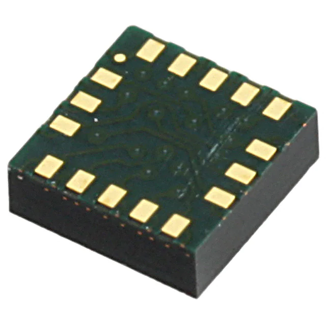
- Part No.:
- H3LIS331DLTR
- Manufacturer:
- STMicroelectronics
- Category:
- Accelerometers
- Package:
- 16-VFLGA
- Datasheet:
-
 H3LIS331DLTR.pdf
- Description:
- ACCEL 100-400G I2C/SPI 16TFLGA
- Quantity:
- Payment:

- Shipping:

Inventory:3,630
Please send an inquiry. Send us your inquiry, and we will respond immediately.
Product details
Overview
H3LIS331DLTR from STMicroelectronics is a high-g, low-power 3-axis digital accelerometer with I²C/SPI interface, ±100g/±200g/±400g dynamically selectable full scales, 0.5 Hz–1 kHz output data rate, and 7 µA low-power mode current. It delivers shock detection and impact logging in wearables, sports concussion monitoring, and asset tracking systems.
For engineers reviewing the H3LIS331DLTR datasheet, H3LIS331DLTR pinout, H3LIS331DLTR application, or H3LIS331DLTR equivalent, key selection criteria include programmable inertial interrupts (INT1/INT2), factory-calibrated sensitivity (±0.01 %/°C TCSo), dual supply rails (Vdd: 2.16–3.6 V, Vdd_IO: 1.71–Vdd+0.1 V), and TFLGA-16L 3×3×1.0 mm³ package compatibility with ECOPACK/RoHS requirements.
Technical Context
The H3LIS331DLTR integrates a surface-micromachined capacitive MEMS sensing element with a low-noise charge amplifier and 12-bit ADC, enabling DC-coupled acceleration measurement across three orthogonal axes. Its digital interface supports both I²C (up to 400 kHz fast mode) and SPI (up to 10 MHz), with CS pin selecting protocol mode and SA0 configuring I²C slave address (0011000/0011001).
It implements two independent programmable interrupt generators for motion detection, free-fall, and wake-up events, coupled with sleep-to-wake functionality that transitions automatically from low-power mode (0.5–10 Hz ODR) to full-performance mode (up to 1 kHz) upon threshold crossing. Factory-trimmed sensitivity and zero-g offset are stored in nonvolatile memory and loaded at power-on.
Key Specifications
| Parameter | Value and Actual Design Meaning |
|---|---|
| Full Scale Range | ±100g / ±200g / ±400g - user-selectable via register bits; determines resolution (49/98/195 mg/digit) and usable dynamic range |
| Output Data Rate (ODR) | 0.5 Hz to 1 kHz - configurable in normal mode (50/100/400/1000 Hz) and low-power mode (0.5–10 Hz); sets system latency and bandwidth |
| Supply Current | 7 µA (low-power mode, 0.5 Hz ODR) - enables multi-year battery life in wearable impact loggers and asset trackers |
| Sensitivity Tempco | ±0.01 %/°C - ensures stable g-to-digital conversion across -40°C to +85°C industrial temperature range without recalibration |
| Shock Survivability | 10000 g for 0.1 ms - validated mechanical robustness for crash detection and high-impact sports applications |
| Digital Interface | I²C (400 kHz fast mode) and SPI (10 MHz, 3-/4-wire) - dual-protocol flexibility for microcontroller integration without external level shifters |
| Zero-g Offset Accuracy | ±1 g typical (calibrated at ±1 g) - factory-trimmed offset reduces need for host-side calibration in production firmware |
Pinout & Package
Package: TFLGA-16L, 3 × 3 × 1.0 mm³, land grid array with exposed pad (RoHS/ECOPACK compliant). Pin 1 indicator located at top-left corner (top view).
| Pin/Terminal | Circuit Role | Design Meaning |
|---|---|---|
| 1 Vdd_IO | I/O power supply rail | Supplies 1.71–Vdd+0.1 V to all digital pins; decoupled separately from core Vdd; enables 1.8 V logic compatibility |
| 4 SCL/SPC | Serial clock input | Shared I²C clock (SCL) or SPI clock (SPC); supports up to 400 kHz (I²C) or 10 MHz (SPI) |
| 6 SDA/SDI/SDO | Bidirectional serial data | I²C data (SDA), SPI input (SDI), or 3-wire SPI output (SDO); internal pull-ups eliminate external resistors |
| 7 SDO/SA0 | Output/data address select | Configures I²C slave address LSB (0011000 or 0011001); also serves as SPI 4-wire output (SDO) |
| 8 CS | Interface mode select | High = I²C mode; Low = SPI enabled; critical for protocol initialization and bus arbitration |
| 9 & 11 INT1/INT2 | Programmable inertial interrupts | Open-drain outputs driven by configurable motion/fall/wake-up events; support push-pull via external pull-up |
| 14 Vdd | Analog/MEMS core supply | 2.16–3.6 V main supply; powers sensing element and analog chain; may be removed while retaining I²C/SPI communication |
| 5/12/13/16 GND | Ground reference | Four dedicated ground terminals minimize noise coupling and improve EMI immunity in high-shock environments |
Key Features
| Feature | Design Value |
|---|---|
| Dynamic Full-Scale Selection | Runtime reconfiguration of ±100g/±200g/±400g via control register - optimizes resolution vs. range trade-off per use case (e.g., ±100g for concussion detection, ±400g for crash event capture) |
| Sleep-to-Wake Functionality | Automatic transition from 0.5 Hz low-power mode to 1 kHz full-rate mode upon interrupt trigger - eliminates polling overhead and extends battery life in always-on impact monitors |
| Factory-Calibrated Sensitivity & Offset | Trim values stored in nonvolatile memory and auto-loaded at boot - removes requirement for end-equipment calibration and reduces firmware complexity |
| Dual Independent Interrupt Outputs | INT1 and INT2 independently configurable for different event types (e.g., INT1 = free-fall, INT2 = high-g shock) - enables parallel real-time response without MCU intervention |
| 10000 g Shock Survivability | Validated mechanical resilience to transient overloads - ensures operational continuity after severe impacts in automotive crash sensors and sports equipment |
Applications
| Car Crash Detection | Concussion Monitoring |
|---|---|
|
Use Scenario: Mounted inside vehicle cabin or seat structure to detect rapid deceleration exceeding 50 g within 10 ms. IC Role / Device Role / Timing Role: Primary high-g event sensor triggering airbag deployment logic and black-box data capture. Use Value: 10000 g survivability ensures operation post-impact; ±400g full scale captures peak crash transients without saturation. |
Use Scenario: Integrated into helmet-mounted electronics to identify head accelerations > 80 g lasting ≥1 ms during contact sports. IC Role / Device Role / Timing Role: Real-time inertial monitor feeding edge AI inference engine for on-device concussion risk classification. Use Value: Programmable INT1/INT2 allow simultaneous detection of linear and rotational acceleration thresholds; 7 µA low-power mode enables continuous logging. |
| Asset Impact Logging | Augmented Sports Equipment |
|
Use Scenario: Embedded in shipping containers or logistics pallets to record drop height, orientation, and impact severity during transit. IC Role / Device Role / Timing Role: Standalone shock logger with timestamped event storage triggered by configurable high-g interrupts. Use Value: Factory-calibrated sensitivity ensures consistent g-level reporting across units; TFLGA-16L package withstands vibration and thermal cycling in warehouse environments. |
Use Scenario: Mounted in baseball bats or tennis rackets to measure swing kinematics, impact force, and recoil dynamics. IC Role / Device Role / Timing Role: High-bandwidth motion capture node synchronizing with BLE radio for real-time biomechanical feedback. Use Value: 1 kHz ODR captures transient bat-ball collision events; dual interrupt outputs flag swing initiation and impact separately for algorithm segmentation. |
Equivalent & Alternatives
The following parts are listed as comparable options for similar high-g accelerometer applications.
| Alternative Part | Technical Difference | Application Difference | Selection Advice |
|---|---|---|---|
| ADXL372BCPZ | 2000 g range, 200 Hz max ODR, 22 µA typical current, integrated FFT engine | Optimized for vibration analysis, not shock/event logging; lacks sleep-to-wake and dual interrupts | Prefer for predictive maintenance; avoid when sub-10 ms event timing or ultra-low power are required |
| LSM303AGR | ±2/±4/±8 g range, 1.9 mA current, integrated magnetometer, no high-g capability | Designed for tilt/orientation, not impact detection; unsuitable for >10 g applications | Only viable for low-g motion sensing; cannot substitute for crash or concussion use cases |
Compared with ADXL372BCPZ and LSM303AGR, the H3LIS331DLTR uniquely combines 10000 g survivability, programmable dual interrupts, and 7 µA low-power operation-making it the only option among the three qualified for battery-powered, high-shock event detection in wearables and automotive safety systems.
Availability
H3LIS331DLTR is available at Aetrix Electronics and suitable for car crash detection systems, concussion monitoring wearables, asset impact loggers, and augmented sports equipment requiring stable component supply across extended temperature ranges (-40°C to +85°C) and long-lifecycle production.
Supply support for H3LIS331DLTR includes scheduled delivery planning, volume procurement assistance, BOM continuity management, traceable sourcing, and lifecycle availability coordination for OEM customers, industrial embedded developers, connected-device designers, and electronics production programs.
Manufacturer
STMicroelectronics is a global semiconductor leader headquartered in Geneva, Switzerland, designing and manufacturing microcontrollers, sensors, power ICs, and analog devices for industrial, automotive, and consumer markets.
The H3LIS331DLTR belongs to ST's high-g MEMS accelerometer product line, engineered specifically for reliable shock and impact detection in safety-critical and battery-constrained applications where mechanical robustness and ultra-low power are mandatory.
FAQ
What is the minimum supply voltage required for H3LIS331DLTR operation?
The H3LIS331DLTR requires Vdd between 2.16 V and 3.6 V for analog/MEMS core operation, and Vdd_IO between 1.71 V and Vdd+0.1 V for I/O pins. Both supplies must be present simultaneously for full functionality; however, Vdd may be removed while maintaining Vdd_IO to retain I²C/SPI communication with the measurement chain powered off.
How does the sleep-to-wake-up feature function in practice?
Sleep-to-wake operates by configuring the device in low-power mode (e.g., 0.5 Hz ODR), where it continuously monitors acceleration but consumes only 7 µA. When a programmable interrupt condition (e.g., >100 g for 2 ms) occurs on INT1 or INT2, the device autonomously increases ODR to full rate (e.g., 1 kHz) and asserts the interrupt pin-enabling immediate high-fidelity data capture without MCU polling.
Can H3LIS331DLTR be used with a 1.8 V microcontroller without level shifters?
Yes. The H3LIS331DLTR supports 1.8 V I/O compatibility via its separate Vdd_IO rail (1.71–Vdd+0.1 V), and includes internal pull-up resistors on SDA and SCL lines. When Vdd_IO = 1.8 V, all digital pins meet 1.8 V logic thresholds (VIH = 1.44 V, VOL = 0.18 V), eliminating need for external level translation in 1.8 V systems.
What is the significance of the "10000 g high-shock survivability" specification?
This rating means the H3LIS331DLTR has been tested and verified to remain functional after exposure to mechanical shocks of 10000 g for 0.1 ms or 3000 g for 0.5 ms-conditions representative of automotive crashes or sports impacts. It reflects mechanical design margin, not measurement range; the device measures up to ±400 g but survives far higher transient overloads without damage.
H3LIS331DLTR Specifications
- Product attributes
- Attribute value
- Manufacturer:
- STMicroelectronics
- Series:
- -
- Package/Case:
- 16-VFLGA
- Packaging:
- Tape & Reel (TR)
- Product Status:
- Active
- Type:
- Digital
- Axis:
- X, Y, Z
- Acceleration Range:
- ±100g, ±200g, ±400g
- Sensitivity (LSB/g):
- 20 (±100g) ~ 5 (±400g)
- Sensitivity (mV/g):
- -
- Bandwidth:
- 25Hz ~ 500Hz
- Output Type:
- I2C, SPI
- Voltage - Supply:
- 2.16V ~ 3.6V
- Features:
- Adjustable Bandwidth, Selectable Scale, Sleep Mode
- Operating Temperature:
- -40°C ~ 85°C
- Grade:
- -
- Qualification:
- -
- Mounting Type:
- Surface Mount
- Supplier Device Package:
- 16-TFLGA (3x3)
H3LIS331DLTR FAQ
1.How can I place an order for H3LIS331DLTR through Aetrix?
Please submit a Request for Quotation (RFQ) for H3LIS331DLTR on Aetrix. Our sales agent will provide a competitive quotation and guide you through the order confirmation once you accept the terms.
2.Are the price and stock information for H3LIS331DLTR reliable?
The price and inventory of H3LIS331DLTR are updated periodically and may fluctuate due to market conditions. Stock and pricing data are typically refreshed every 24 hours. Quotation validity for H3LIS331DLTR is usually 5 days.
3.What payment methods are accepted for H3LIS331DLTR?
We accept Wire Transfer, PayPal, Credit Card, Western Union, MoneyGram, and Escrow for H3LIS331DLTR transactions.
Note: Certain payment methods may incur a processing fee.
4.How is shipping managed for H3LIS331DLTR?
H3LIS331DLTR orders can be shipped via leading logistics carriers, including DHL, UPS, FedEx, TNT, or Registered Mail.
Once your H3LIS331DLTR order is processed, you will receive an email with the shipment details and tracking number.
Note: Tracking information may take up to 24 hours to appear. Express delivery typically takes 3–5 business days.
5.How can I obtain technical support or documentation for H3LIS331DLTR?
For technical support, including H3LIS331DLTR datasheets, pinout diagrams, or application guidance, please contact our engineering support team. They can provide detailed documentation and assistance for your H3LIS331DLTR requirements.
6.How does Aetrix verify that H3LIS331DLTR is sourced from the original manufacturer or authorized distributors?
All H3LIS331DLTR products on Aetrix are procured from qualified distributors and authorized channels. Our dedicated quality assurance team conducts strict verification, including traceability checks and, if necessary, third-party testing. This ensures that H3LIS331DLTR meets industry standards.
7.What is the process for return or replacement of H3LIS331DLTR?
All H3LIS331DLTR units undergo pre-shipment inspection (PSI). If there is an issue with H3LIS331DLTR, returns or replacements are accepted under the following conditions:
1.Quantity discrepancies, incorrect items, or visible external defects (such as breakage or corrosion), acknowledged by Aetrix.
2.The issue is reported within 90 days of delivery.
3.The H3LIS331DLTR part is unused and in its original packaging.
Return procedure for H3LIS331DLTR:
1.Submit a request within 90 days.
2.Obtain a Return Material Authorization (RMA) from Aetrix.
H3LIS331DLTR Tags

-
MXC4005XC
Memsic Inc.

-
MC3419
Memsic Inc.

-
MC3479
Memsic Inc.

-
MXC6655XA
Memsic Inc.

-
MC3630
Memsic Inc.
.jpg)
-
LIS2HH12TR
STMicroelectronics

-
KX122-1037
Kionix Inc.
-
LIS2DE12TR
STMicroelectronics
-
LIS2DH12TR
STMicroelectronics

-
MC3635
Memsic Inc.
-
LIS2DS12TR
STMicroelectronics

-
LIS3DHTR
STMicroelectronics
Tech Hub

A practical engineering and sourcing framework covering lifecycle verification, lifetime-buy calculations, replacement qualification, supplier checks and counterfeit-risk controls.

TTL and CMOS logic families differ in thresholds, loading, output drive, power and timing. This engineering guide compares 74HC and 74HCT, calculates noise margins and checks 3.3 V/5 V compatibility.

A practical engineering guide to 3.3V and 5V logic compatibility, input thresholds, resistor dividers, translator ICs, MOSFET level shifting, I2C pull-ups, timing limits and power-sequencing risks.

The 74HC595 uses push-pull logic outputs, while the TPIC6B595 uses 50 V open-drain DMOS sinks for higher-power loads. This guide compares timing, current limits, 3.3 V interfacing, load wiring, thermal…

The 74HC595 converts serial data into eight stable parallel outputs. This guide covers pin functions, shift and storage timing, OE and MR behavior, drive-current limits, cascading, voltage compatibilit…

A technical comparison of level-sensitive latches and edge-triggered flip-flops, covering timing windows, setup and hold limits, master–slave operation, time borrowing, race-through, HDL inference and…

A D latch stores one bit while Enable controls when data can pass. This reference covers gate-level operation, truth tables, transparency, setup and hold timing, LE versus OE, common ICs and practical …

An SR latch stores one bit through cross-coupled feedback. This engineering reference covers NOR and NAND implementations, truth tables, forbidden-state recovery, gated operation, switch debouncing, fa…

Latch circuits retain one bit through feedback. This technical reference covers SR and D latches, truth tables, transparency, timing limits, latch-versus-flip-flop behavior, applications and common log…

An engineering guide to LED driver operation, constant-current and constant-voltage outputs, linear and switching topologies, dimming, IC selection, calculations, replacement compatibility, and fault c…


