
 My Inquiry
 My Account


NXP Semiconductors HTRC11001T/03EE,11
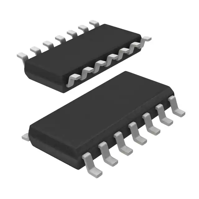
- Part No.:
- HTRC11001T/03EE,11
- Manufacturer:
- NXP Semiconductors
- Category:
- RFID, RF Access, Monitoring ICs
- Package:
- 14-SOIC (0.154", 3.90mm Width)
- Datasheet:
-
 HTRC11001T/03EE,11.pdf
- Description:
- IC RFID READER 125KHZ 14SO
- Quantity:
- Payment:

- Shipping:

Inventory:4,405
Please send an inquiry. Send us your inquiry, and we will respond immediately.
Product details
Overview
HTRC11001T/03EE from NXP Semiconductors is a 125 kHz RFID reader IC optimized for HITAG transponder communication, featuring adaptive sampling time (AST) demodulation, dual TX driver outputs (TX1/TX2), and a programmable 4–16 MHz oscillator for precise 125 kHz carrier generation. It supports AM/PM read and amplitude-modulated write operations in livestock tracking, industrial access control, and logistics asset identification systems.
For engineers reviewing the HTRC11001T/03EE datasheet, HTRC11001T/03EE pinout, HTRC11001T/03EE application, or HTRC11001T/03EE equivalent, key selection considerations include AST-based antenna detuning compensation, on-chip phase measurement (±5.7° error), 200 mAp continuous antenna drive capability, SO14 package compatibility, and support for three-wire or two-wire microcontroller interface configurations.
Technical Context
The HTRC11001T/03EE integrates a full-bridge antenna driver delivering ~10 Vpp excitation to a series-resonant LC tank (125 kHz), with internal current limiting and real-time antenna rupture/short-circuit detection via ANTFAIL status bit. Its adaptive sampling time (AST) technique uses on-chip phase measurement (360°/64 resolution) to dynamically adjust demodulator sampling timing based on antenna tuning drift.
The IC employs a synchronous AM/PM demodulator with programmable second-order low-pass/high-pass filters (cutoffs: 3/6 kHz and 40/160 Hz), configurable amplifier gains (gain0 = 16/32, gain1 = 6.22/31.5), and a digitizer with smart comparator and amplitude reference acquisition (AMPCOMP). All configuration parameters are stored across four user-accessible pages via SET_CONFIG_PAGE/GET_CONFIG_PAGE commands.
Key Specifications
| Parameter | Value and Actual Design Meaning |
|---|---|
| Operating Frequency | 125 kHz carrier generated from 4/8/12/16 MHz programmable oscillator - enables precise RF field control without external frequency synthesis. |
| Antenna Drive Capability | 200 mAp continuous output per TX1/TX2 - sufficient to energize standard 125 kHz reader coils (e.g., 1–10 mH) at typical read ranges (≤15 cm). |
| Demodulator Sensitivity | 1 mVPP at RX input - allows reliable decoding of weak transponder backscatter signals even under marginal coupling conditions. |
| Phase Measurement Resolution | 5.625° (360°/64) - enables fine-grained AST calibration to compensate for ±10% antenna component tolerance or environmental detuning. |
| Supply Voltage Range | 4.5 V to 5.5 V - compatible with standard 5 V industrial power rails; includes internal regulation and 100 nF bypass requirement near VDD. |
| Power-Down Current | <20 μA - supports battery-powered or energy-constrained reader designs requiring ultra-low standby consumption. |
| Operating Temperature | −40 °C to +85 °C - validated for deployment in uncontrolled industrial and outdoor environments including livestock barns and warehouse docks. |
Pinout & Package
Package: SO14 (SOT108-1), plastic small outline, 14 leads, 3.9 mm body width, 1.27 mm pitch.
| Pin/Terminal | Circuit Role | Design Meaning |
|---|---|---|
| VSS | Ground reference | Negative supply return for digital and analog sections; must be connected to system GND with low-impedance path. |
| TX2 | Antenna driver output | Full-bridge output terminal driving one side of series-resonant LC antenna circuit; complements TX1 for differential excitation. |
| VDD | Positive supply input | Stabilized 5 V ±10% input; powers all internal blocks; requires local 100 nF ceramic bypass capacitor. |
| TX1 | Antenna driver output | Full-bridge output terminal driving opposite side of LC antenna; combined TX1/TX2 deliver ~10 Vpp square wave. |
| MODE | Digital filter enable | When tied to VDD, enables glitch filtering on SCLK/DIN for noise immunity in long-cable active antenna applications. |
| XTAL1 | Oscillator input / external clock | Accepts crystal, ceramic resonator, or CMOS-level external clock (4–16 MHz); also serves as clock source input when crystal not used. |
| XTAL2 | Oscillator output | Crystal/resonator output node; forms Pierce oscillator with XTAL1; no external connection required if using external clock. |
| SCLK | Serial interface clock | Microcontroller-generated clock for bidirectional command/data transfer; Schmitt-trigger input for noise rejection. |
| DIN | Serial data input | Command and configuration data input from microcontroller; Schmitt-trigger input; low-to-high transition initializes interface. |
| DOUT | Serial data output | Open-drain output with internal pull-up; delivers demodulated tag data, status bits (ANTFAIL, AMPCOMP), and config page reads. |
| n.c. | No connection | Pin 11 is internally unconnected; must remain floating or grounded per PCB layout best practices. |
| CEXT | High-pass filter coupling | Connects to external capacitor forming high-pass stage with internal resistor; sets lower cutoff frequency (40/160 Hz). |
| QGND | Analog ground bias | Internal analog reference point (0.35 × VDD); separates analog signal path from digital ground to reduce noise coupling. |
| RX | Demodulator input | Accepts divided antenna tap voltage (−8 V to +8 V w.r.t. QGND); feeds adaptive sampling time AM/PM demodulator chain. |
Key Features
| Feature | Design Value |
|---|---|
| Adaptive Sampling Time (AST) | Compensates antenna detuning by measuring phase shift (5.625° resolution) and adjusting demodulator sampling instant - eliminates need for precision-tuned 125 kHz coils. |
| Antenna Diagnostics | Real-time monitoring of antenna tap voltage detects open-circuit (ANTFAIL = 1) or short-circuit failure during every coil driver cycle - enables fail-safe reader operation. |
| Programmable Filter/Amplifier | Four configuration pages allow dynamic adjustment of LPF/HPF cutoffs (3/6 kHz, 40/160 Hz) and amplifier gains (16/32×, 6.22/31.5×) to match diverse transponder modulation profiles. |
| Low-Power Modes | Idle mode (≤0.4 mA) and power-down mode (<20 μA) controlled via PD/PD_MODE bits - extends battery life in portable or solar-powered readers. |
| Flexible Serial Interface | Three-wire (SCLK/DIN/DOUT) or two-wire (DIN/DOUT tied) configuration; Schmitt-trigger inputs and open-drain DOUT simplify MCU integration across 3.3 V/5 V platforms. |
Applications
| Livestock Tracking | Industrial Access Control |
|---|---|
Use Scenario: Implantable or ear-tag RFID readers mounted on farm gateways scan cattle tags during passage to log identity, health history, and movement. IC Role / Device Role / Timing Role: HTRC11001T/03EE acts as the RF front-end transceiver, generating 125 kHz field, demodulating tag responses via AST, and interfacing with gateway MCU over serial bus. Use Value: AST compensates for variable tag orientation and antenna detuning caused by metal/water proximity in barn environments - ensures >99.5% read reliability without manual recalibration. |
Use Scenario: Fixed-mount readers authenticate personnel badges at factory entrances, machine tool doors, or hazardous material storage zones. IC Role / Device Role / Timing Role: HTRC11001T/03EE provides robust 125 kHz read/write capability with antenna fault detection, enabling safe door unlock only after verified tag presence and integrity check. Use Value: Built-in ANTFAIL monitoring prevents false unlocks due to damaged or disconnected antennas - critical for safety-critical access enforcement. |
| Logistics Asset Management | Automated Tool Tracking |
Use Scenario: Handheld or dock-mounted readers identify pallets, containers, or reusable shipping crates tagged with HITAG transponders in warehouses and distribution centers. IC Role / Device Role / Timing Role: HTRC11001T/03EE handles high-speed tag interrogation using WRITE_TAG_N for precise pulse-width-controlled programming and READ_TAG for fast data retrieval. Use Value: Programmable 4–16 MHz oscillator allows consistent 125 kHz carrier generation across varying supply voltages and temperatures - maintains read range stability during battery discharge or thermal cycling. |
Use Scenario: Tool cabinets with embedded readers verify tool check-in/out by scanning ISO/IEC 11784-compliant transponders embedded in wrenches, torque drivers, or calipers. IC Role / Device Role / Timing Role: HTRC11001T/03EE performs rapid phase measurement and AST calibration before each read cycle to accommodate misaligned tools inside metal enclosures. Use Value: On-chip phase measurement (±5.7° error) and freeze-mode settling acceleration (TRAST ≤1.5 ms) reduce per-tag transaction time to <100 ms - enabling high-throughput tool accountability. |
Equivalent & Alternatives
The following parts are listed as comparable options for similar RFID reader IC applications.
| Alternative Part | Technical Difference | Application Difference | Selection Advice |
|---|---|---|---|
| SLRC610/021/022 | Integrated NFC/RFID frontend supporting 13.56 MHz ISO 14443 A/B and 125 kHz EM4100 protocols; lacks AST and dedicated 125 kHz optimization. | Targets dual-frequency (HF + LF) readers; unsuitable for legacy 125 kHz-only infrastructure like livestock ear tags or older access cards. | Select SLRC610 only when migrating to multi-protocol systems; HTRC11001T/03EE remains optimal for cost-sensitive, single-band 125 kHz deployments. |
| TRF7960ARHBT | Multi-standard 13.56 MHz reader IC with software-configurable modulation; no native 125 kHz support or AST capability. | Designed for contactless smart card, payment, and NFC applications; cannot replace HTRC11001T/03EE in low-frequency animal ID or industrial proximity systems. | TRF7960ARHBT is not a functional alternative for 125 kHz use cases; consider only if redesigning for HF-based infrastructure with new tag standards. |
Compared with SLRC610/021/022 and TRF7960ARHBT, the HTRC11001T/03EE delivers superior 125 kHz link budget, deterministic AST-based timing recovery, and lower BOM count for dedicated LF readers - making it irreplaceable in cost-optimized, single-band livestock and industrial tagging systems.
Availability
HTRC11001T/03EE is available at Aetrix Electronics and suitable for livestock tracking, industrial access control, and logistics asset management requiring stable component supply across extended production lifecycles.
Supply support for HTRC11001T/03EE includes scheduled delivery planning, volume procurement assistance, BOM continuity management, traceable sourcing, and lifecycle availability coordination for OEM customers, industrial embedded developers, connected-device designers, and electronics production programs.
Manufacturer
NXP Semiconductors is a global semiconductor leader specializing in secure connectivity solutions for automotive, industrial, and IoT applications, with deep expertise in RFID, NFC, and secure element technologies.
The HTRC11001T/03EE belongs to NXP's legacy HITAG reader IC family, designed specifically for high-reliability, low-cost 125 kHz RFID systems in harsh environments where antenna detuning and power constraints dominate design requirements.
FAQ
What is the primary function of the HTRC11001T/03EE in an RFID system?
The HTRC11001T/03EE serves as a complete 125 kHz RFID reader transceiver IC, generating the carrier field via its dual TX drivers, demodulating transponder responses using adaptive sampling time (AST), and providing a serial interface to a host microcontroller. It handles both read and write operations for HITAG and other AM/PM-compatible transponders, with built-in diagnostics and programmable filtering - all integrated into a single SO14 package.
How does the Adaptive Sampling Time (AST) feature improve performance of the HTRC11001T/03EE?
The AST feature in the HTRC11001T/03EE measures the phase difference between the TX driver signal and antenna tap voltage (with 5.625° resolution) and dynamically adjusts the demodulator sampling instant to compensate for antenna detuning. This eliminates sensitivity to ±10% component tolerances in LC tanks and environmental shifts, enabling reliable operation without precision-tuned coils - a critical advantage in livestock and industrial deployments where antenna placement varies.
Can the HTRC11001T/03EE operate with an external clock instead of a crystal?
Yes, the HTRC11001T/03EE supports external clock injection via the XTAL1 pin. A CMOS-compatible clock signal in the 4–16 MHz range can be fed directly into XTAL1, bypassing the internal crystal oscillator. This allows synchronization with a system microcontroller's clock domain or elimination of the crystal/resonator for cost and board space savings - while maintaining full 125 kHz carrier generation accuracy via the internal programmable divider.
What diagnostic capabilities does the HTRC11001T/03EE provide for antenna health monitoring?
The HTRC11001T/03EE continuously monitors antenna integrity by sensing the tap voltage level relative to the diagnosis threshold (DLEV = −0.8 to −1.5 V). If the voltage fails to go sufficiently negative during each driver cycle, the ANTFAIL status bit is set - indicating an open or shorted antenna. This real-time fault detection is accessible via GET_CONFIG_PAGE command and enables fail-safe behavior in mission-critical readers such as access control or automated tool cabinets.
What are the power consumption characteristics of the HTRC11001T/03EE in different operating modes?
The HTRC11001T/03EE draws ≤10 mA during active operation (IOn), ≤0.4 mA in idle mode (Iid), and <20 μA in power-down mode (Ipd). These values are measured at VDD = 5.5 V and reflect its suitability for battery-powered handheld readers or energy-constrained fixed installations. The low-power modes are controlled via PD and PD_MODE configuration bits, allowing firmware-driven power state management without external circuitry.
HTRC11001T/03EE,11 Specifications
- Product attributes
- Attribute value
- Manufacturer:
- NXP Semiconductors
- Series:
- HITAG® 1
- Package/Case:
- 14-SOIC (0.154", 3.90mm Width)
- Packaging:
- Tape & Reel (TR)
- Product Status:
- Active
- Type:
- RFID Reader
- Frequency:
- 125kHz
- Standards:
- -
- Interface:
- -
- Voltage - Supply:
- 4.5V ~ 5.5V
- Operating Temperature:
- -40°C ~ 85°C
- Grade:
- -
- Qualification:
- -
- Mounting Type:
- Surface Mount
- Supplier Device Package:
- 14-SO
HTRC11001T/03EE,11 FAQ
1.How can I place an order for HTRC11001T/03EE,11 through Aetrix?
Please submit a Request for Quotation (RFQ) for HTRC11001T/03EE,11 on Aetrix. Our sales agent will provide a competitive quotation and guide you through the order confirmation once you accept the terms.
2.Are the price and stock information for HTRC11001T/03EE,11 reliable?
The price and inventory of HTRC11001T/03EE,11 are updated periodically and may fluctuate due to market conditions. Stock and pricing data are typically refreshed every 24 hours. Quotation validity for HTRC11001T/03EE,11 is usually 5 days.
3.What payment methods are accepted for HTRC11001T/03EE,11?
We accept Wire Transfer, PayPal, Credit Card, Western Union, MoneyGram, and Escrow for HTRC11001T/03EE,11 transactions.
Note: Certain payment methods may incur a processing fee.
4.How is shipping managed for HTRC11001T/03EE,11?
HTRC11001T/03EE,11 orders can be shipped via leading logistics carriers, including DHL, UPS, FedEx, TNT, or Registered Mail.
Once your HTRC11001T/03EE,11 order is processed, you will receive an email with the shipment details and tracking number.
Note: Tracking information may take up to 24 hours to appear. Express delivery typically takes 3–5 business days.
5.How can I obtain technical support or documentation for HTRC11001T/03EE,11?
For technical support, including HTRC11001T/03EE,11 datasheets, pinout diagrams, or application guidance, please contact our engineering support team. They can provide detailed documentation and assistance for your HTRC11001T/03EE,11 requirements.
6.How does Aetrix verify that HTRC11001T/03EE,11 is sourced from the original manufacturer or authorized distributors?
All HTRC11001T/03EE,11 products on Aetrix are procured from qualified distributors and authorized channels. Our dedicated quality assurance team conducts strict verification, including traceability checks and, if necessary, third-party testing. This ensures that HTRC11001T/03EE,11 meets industry standards.
7.What is the process for return or replacement of HTRC11001T/03EE,11?
All HTRC11001T/03EE,11 units undergo pre-shipment inspection (PSI). If there is an issue with HTRC11001T/03EE,11, returns or replacements are accepted under the following conditions:
1.Quantity discrepancies, incorrect items, or visible external defects (such as breakage or corrosion), acknowledged by Aetrix.
2.The issue is reported within 90 days of delivery.
3.The HTRC11001T/03EE,11 part is unused and in its original packaging.
Return procedure for HTRC11001T/03EE,11:
1.Submit a request within 90 days.
2.Obtain a Return Material Authorization (RMA) from Aetrix.
HTRC11001T/03EE,11 Tags

-
SL2S2602FTBX
NXP Semiconductors

-
ST25DV04K-IER6S3
STMicroelectronics

-
ST25DV04K-IER6C3
STMicroelectronics
-
LXMSJZNCMD-217
Murata Electronics

-
NT3H2111W0FTTJ
NXP Semiconductors

-
NT3H2111W0FHKH
NXP Semiconductors

-
M24LR04E-RMC6T/2
STMicroelectronics
-
ST25DV04KC-JF6D3
STMicroelectronics

-
ST25DV64KC-IE6S3
STMicroelectronics

-
ST25DV64K-IER6T3
STMicroelectronics
-
NT3H2211W0FTTJ
NXP Semiconductors
-
NT3H2211W0FHKH
NXP Semiconductors
Tech Hub

An SR latch stores one bit through cross-coupled feedback. This engineering reference covers NOR and NAND implementations, truth tables, forbidden-state recovery, gated operation, switch debouncing, fa…

Latch circuits retain one bit through feedback. This technical reference covers SR and D latches, truth tables, transparency, timing limits, latch-versus-flip-flop behavior, applications and common log…

An engineering guide to LED driver operation, constant-current and constant-voltage outputs, linear and switching topologies, dimming, IC selection, calculations, replacement compatibility, and fault c…

Operational amplifier guide covering op amp basics, feedback, ideal vs real op amps, common configurations, buffer circuits, offset, bias current, gain-bandwidth, slew rate, rail-to-rail limits and sel…

Jumper cables guide covering safe connection order, red and black clamp placement, final ground connection, cable gauge, length, clamp quality, copper vs CCA cables, jump starter comparison and battery…

LDO regulator guide covering low dropout voltage, power dissipation, thermal design, PSRR, output noise, capacitor stability, adjustable LDO circuits, LDO vs buck converter and datasheet selection chec…

Conditional Access Module guide covering CAM meaning, CI/CI+ interface, smart card authorization, DVB security workflow, TV and set-top box compatibility, internal electronics, ESD protection, connecto…

Guide to electronic component obsolescence covering EOL risk, PCN/PDN notices, last-time buy planning, replacement options, form-fit-function validation, counterfeit risk and BOM lifecycle management.

18650 battery guide covering lithium-ion cell basics, 3.6V/3.7V voltage, 4.2V charging, mAh and Wh capacity, protected cells, chargers, BMS, series-parallel packs, holders, welding and sourcing checks.…

Hall effect sensor guide covering working principle, linear and digital sensors, Arduino circuits, current sensing, speed detection, automotive applications, A3144 examples, signal filtering and datash…


