
 My Inquiry
 My Account


STMicroelectronics LPR510ALTR
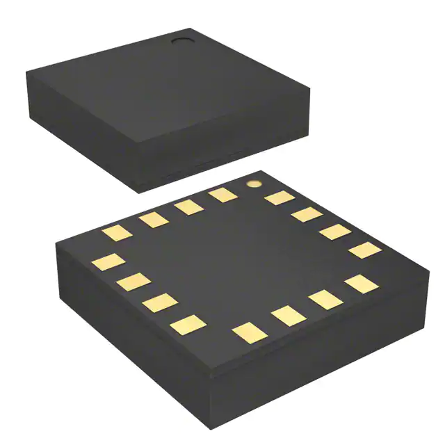
- Part No.:
- LPR510ALTR
- Manufacturer:
- STMicroelectronics
- Category:
- Gyroscopes
- Package:
- 16-LFLGA
- Datasheet:
-
 LPR510ALTR.pdf
- Description:
- GYROSCOPE MEMS DUAL AXIS 16-LGA
- Quantity:
- Payment:

- Shipping:

Inventory:2,776
Please send an inquiry. Send us your inquiry, and we will respond immediately.
Product details
Overview
LPR510ALTR from STMicroelectronics is a dual-axis MEMS gyroscope measuring angular rate along pitch and roll axes with ±100°/s full-scale range, 140 Hz bandwidth, and analog outputs (1× and 4× amplified per axis). It operates from 2.7–3.6 V, supports -40°C to +85°C, and integrates self-test, power-down, and embedded low-pass filtering - deployed in motion-controlled pointing devices and GPS navigation systems.
For engineers reviewing the LPR510ALTR datasheet, LPR510ALTR pinout, LPR510ALTR application, or LPR510ALTR equivalent, key selection criteria include its dual-axis analog output architecture, temperature-stable zero-rate level (1.23 V), sensitivity matching (10 mV/°/s for 4× outputs), and LGA-16 package compatibility with high-shock industrial environments.
Technical Context
The LPR510ALTR implements a Coriolis-based sensing principle using a single micromachined driving mass oscillating continuously; angular rotation induces orthogonal displacement sensed by integrated charge amplifiers and demodulators. Its CMOS interface IC provides two independent analog output channels per axis - one unamplified (±400°/s FS) and one 4× amplified (±100°/s FS).
It embeds a PLL-based phase generator for driving/sensing synchronization, supports external LP/HP filtering via dedicated pins (FILTVDD, VCONT, HP), and features logic-controlled functions: ST (self-test activation), PD (power-down), and HP (high-pass filter reset) - all compatible with standard 3.3 V digital I/O levels.
Key Specifications
| Parameter | Value and Actual Design Meaning |
|---|---|
| Full Scale Range | ±100°/s (4× amplified outputs); enables precise low-rate motion detection in UI controllers |
| Bandwidth | 140 Hz (-3 dB); supports real-time response for gaming remotes and robotic stabilization |
| Sensitivity | 10 mV/°/s (4× outputs); delivers 1.0 V output swing at full scale for robust ADC interfacing |
| Zero-Rate Level | 1.23 V (ratiometrically stable); minimizes calibration burden across temperature (-40°C to +85°C) |
| Supply Current | 6.8 mA (active), 1–5 µA (power-down); extends battery life in portable motion-tracking devices |
| Shock Survivability | 10,000 g / 0.1 ms; ensures reliability in handheld and vehicular mounting environments |
| Output Type | Analog voltage (dual-channel X/Y, each with 1× and 4× variants); eliminates need for external ADC in simple feedback loops |
Pinout & Package
LPR510ALTR is housed in a 5 mm × 5 mm × 1.5 mm plastic land grid array (LGA-16) package with exposed pad for thermal and mechanical stability. The bottom-view layout includes 16 solder lands arranged in a 4×4 grid, with pin 1 located at top-left corner (marked by chamfered corner).
| Pin/Terminal | Circuit Role | Design Meaning |
|---|---|---|
| 1 GND | Ground reference | 0 V supply return; must be low-impedance connection to minimize noise coupling into analog outputs |
| 2 FILTVDD | PLL filter node | Connects external RC network (R1=1 MΩ, C1=4.7 µF) to stabilize PLL loop dynamics |
| 3 VCONT | PLL control voltage | Accepts filtered control voltage from FILTVDD; critical for driving frequency accuracy and jitter suppression |
| 4 OUTY | Unamplified Y-axis output | Direct analog voltage proportional to ΩY (±400°/s FS); requires external buffering if routed to ADC |
| 5 4xINY | Y-axis 4× amplifier input | Input node for external high-pass filter; short to GND/Vref when unused to prevent floating |
| 6 4xOUTY | Amplified Y-axis output | Buffered 4× gain output (±100°/s FS); low-impedance drive simplifies connection to downstream circuitry |
| 7 Vref | Internal reference | 1.23 V precision reference shared across outputs; used as bias point for HP/LP filtering networks |
| 8 4xOUTX | Amplified X-axis output | Buffered 4× gain output (±100°/s FS); electrically isolated from Y channel for crosstalk-free operation |
| 9 4xINX | X-axis 4× amplifier input | Input node for external high-pass filter on X channel; tied to Vref/GND when not filtering |
| 10 OUTX | Unamplified X-axis output | Direct analog voltage proportional to ΩX (±400°/s FS); matches OUTY for differential signal processing |
| 11 ST | Self-test control | Logic-high (≥0.8×Vdd) activates electrostatic test force; verifies mechanical integrity and signal chain functionality |
| 12 PD | Power-down control | Logic-high places device in ultra-low-power state (≤5 µA); retains configuration and enables fast wake-up |
| 13 HP | High-pass filter reset | Pulse-high resets external HP filter capacitor; prevents DC drift during startup or overload recovery |
| 14,15 Res | Reserved | Must be connected to Vdd; internal pull-up not guaranteed - hard tie required for stable operation |
| 16 Vdd | Power supply | 2.7–3.6 V single supply; decoupling (100 nF ceramic + 10 µF aluminum) mandatory near pin |
Key Features
| Feature | Design Value |
|---|---|
| Dual-axis analog output architecture | Independent X/Y channels with selectable 1×/4× gain per axis enable flexible resolution scaling without external op-amps |
| Embedded self-test | Electrostatic actuation verifies mechanical integrity and signal path continuity - no external stimulus required |
| Temperature-stable zero-rate level | 1.23 V ±0.02 °/s/°C drift ensures minimal calibration overhead over full industrial temperature range |
| Integrated PLL timing core | On-chip phase-locked loop synchronizes drive and sense interfaces - eliminates need for external clock source |
| Low-power operation | 6.8 mA active current and sub-5 µA power-down mode support battery-powered remote controllers and wearables |
Applications
| GPS Navigation Systems | Motion Tracking |
|---|---|
Use Scenario: Augmenting GPS position fixes with dead-reckoning during signal loss in urban canyons or tunnels. IC Role / Device Role / Timing Role: Dual-axis angular rate sensor providing pitch/roll data to inertial measurement unit (IMU) fusion algorithm. Use Value: Enables continuous heading estimation with <1° RMS error over 30 s GPS outage using ±100°/s full-scale range and 140 Hz bandwidth. | Use Scenario: Capturing human limb orientation for rehabilitation monitoring or sports biomechanics analysis. IC Role / Device Role / Timing Role: MEMS gyroscope delivering time-synchronized analog rate outputs to microcontroller ADC inputs. Use Value: 10 mV/°/s sensitivity and 0.017 °/s/√Hz noise density support sub-degree joint-angle resolution at 100 Hz sampling. |
| Pointing Devices & Game Controllers | Industrial Robotics |
Use Scenario: Translating hand rotation into cursor movement or in-game camera control in wireless remotes. IC Role / Device Role / Timing Role: Low-latency analog angular rate transducer feeding directly into MCU's analog comparator or ADC. Use Value: 4× amplified outputs provide immediate 1 V full-scale swing - eliminating gain-stage design and reducing BOM count. | Use Scenario: Stabilizing end-effector orientation during high-speed pick-and-place operations under vibration. IC Role / Device Role / Timing Role: Pitch/roll rate sensor in closed-loop servo feedback path for robotic wrist articulation. Use Value: 10,000 g shock survivability and -40°C to +85°C operation ensure functional continuity in factory-floor environments. |
Equivalent & Alternatives
The following parts are listed as comparable options for similar dual-axis analog gyroscope applications.
| Alternative Part | Technical Difference | Application Difference | Selection Advice |
|---|---|---|---|
| ADXRS645 | Single-axis, digital SPI output; higher bandwidth (3.3 kHz), wider FS (±2500°/s); requires external ADC and digital interface logic | Better suited for high-bandwidth industrial IMUs; lacks native dual-axis integration and analog simplicity | Select when system already uses SPI infrastructure and requires >1 kHz bandwidth - not for direct LPR510ALTR replacement |
| MPU-6050 | 6-axis combo (3-axis gyro + 3-axis accel); I²C interface; digital output only; lower FS (±250°/s gyro); integrated DMP processor | Targets cost-sensitive consumer wearables; adds accelerometer but removes analog flexibility and standalone gyro precision | Choose for space-constrained designs needing fused motion data - avoid if analog output, low-power, or pure gyro performance is prioritized |
Compared with ADXRS645 and MPU-6050, the LPR510ALTR uniquely delivers true dual-axis analog outputs in a single LGA-16 package with no digital interface overhead, making it optimal for analog-centric motion control where simplicity, low latency, and minimal external components are critical.
Availability
LPR510ALTR is available at Aetrix Electronics and suitable for GPS navigation systems, motion tracking platforms, pointing devices, and industrial robotics requiring stable component supply, long-term lifecycle support, and RoHS-compliant packaging.
Supply support for LPR510ALTR includes scheduled delivery planning, volume procurement assistance, BOM continuity management, traceable sourcing, and lifecycle availability coordination for OEM customers, industrial embedded developers, connected-device designers, and electronics production programs.
Manufacturer
STMicroelectronics is a global semiconductor leader headquartered in Geneva, Switzerland, designing and manufacturing analog, MEMS, power, and microcontroller solutions for industrial, automotive, and consumer markets.
The LPR510ALTR belongs to ST's high-reliability MEMS gyroscope product line, engineered specifically for precision motion sensing in resource-constrained embedded systems where analog output fidelity, temperature stability, and shock resilience are essential.
FAQ
What is the function of the HP pin on the LPR510ALTR?
The HP (High-Pass Filter Reset) pin is a logic-controlled input that resets the external high-pass filter capacitor when driven high. This action clears accumulated DC offset during startup or after large angular transients, ensuring rapid settling of the output baseline. It must be pulsed high briefly at power-on and after any overload condition to maintain accurate zero-rate tracking.
Can both amplified and unamplified outputs be used simultaneously on the same axis?
No - the 4xINX/4xINY pins serve as inputs to the internal 4× amplifier stage, and connecting them to OUTX/OUTY while also using 4xOUTX/4xOUTY creates undefined signal contention. The device supports either the unamplified outputs (OUTX/OUTY) or the amplified outputs (4xOUTX/4xOUTY), not both concurrently on the same axis without external isolation circuitry.
How does the self-test (ST) function verify sensor integrity?
The ST pin activates an electrostatic test force that displaces the micromachined driving mass, emulating a known Coriolis acceleration. When enabled, this produces a predictable DC-level shift in both 4xOUTX and 4xOUTY outputs - typically ~100 mV - confirming mechanical mobility and signal chain gain accuracy without external rotation equipment.
Why must pins 14 and 15 (Res) be connected to Vdd?
Pins 14 and 15 are reserved and internally undefined; STMicroelectronics specifies they must be externally tied to Vdd to ensure stable internal biasing and prevent floating nodes that could induce leakage currents or erratic behavior. Leaving them unconnected violates the recommended operating conditions and may cause output instability or increased power consumption.
LPR510ALTR Specifications
- Product attributes
- Attribute value
- Manufacturer:
- STMicroelectronics
- Series:
- -
- Package/Case:
- 16-LFLGA
- Packaging:
- Tape & Reel (TR)
- Product Status:
- Obsolete
- Type:
- Analog
- Axis:
- X (Pitch), Y (Roll)
- Range °/s:
- ±100
- Sensitivity (LSB/(°/s)):
- -
- Sensitivity (mV/°/s):
- 10
- Bandwidth:
- 140Hz
- Output Type:
- Analog Voltage
- Voltage - Supply:
- 2.7V ~ 3.6V
- Current - Supply:
- 6.8 mA
- Features:
- -
- Operating Temperature:
- -40°C ~ 85°C
- Grade:
- -
- Qualification:
- -
LPR510ALTR FAQ
1.How can I place an order for LPR510ALTR through Aetrix?
Please submit a Request for Quotation (RFQ) for LPR510ALTR on Aetrix. Our sales agent will provide a competitive quotation and guide you through the order confirmation once you accept the terms.
2.Are the price and stock information for LPR510ALTR reliable?
The price and inventory of LPR510ALTR are updated periodically and may fluctuate due to market conditions. Stock and pricing data are typically refreshed every 24 hours. Quotation validity for LPR510ALTR is usually 5 days.
3.What payment methods are accepted for LPR510ALTR?
We accept Wire Transfer, PayPal, Credit Card, Western Union, MoneyGram, and Escrow for LPR510ALTR transactions.
Note: Certain payment methods may incur a processing fee.
4.How is shipping managed for LPR510ALTR?
LPR510ALTR orders can be shipped via leading logistics carriers, including DHL, UPS, FedEx, TNT, or Registered Mail.
Once your LPR510ALTR order is processed, you will receive an email with the shipment details and tracking number.
Note: Tracking information may take up to 24 hours to appear. Express delivery typically takes 3–5 business days.
5.How can I obtain technical support or documentation for LPR510ALTR?
For technical support, including LPR510ALTR datasheets, pinout diagrams, or application guidance, please contact our engineering support team. They can provide detailed documentation and assistance for your LPR510ALTR requirements.
6.How does Aetrix verify that LPR510ALTR is sourced from the original manufacturer or authorized distributors?
All LPR510ALTR products on Aetrix are procured from qualified distributors and authorized channels. Our dedicated quality assurance team conducts strict verification, including traceability checks and, if necessary, third-party testing. This ensures that LPR510ALTR meets industry standards.
7.What is the process for return or replacement of LPR510ALTR?
All LPR510ALTR units undergo pre-shipment inspection (PSI). If there is an issue with LPR510ALTR, returns or replacements are accepted under the following conditions:
1.Quantity discrepancies, incorrect items, or visible external defects (such as breakage or corrosion), acknowledged by Aetrix.
2.The issue is reported within 90 days of delivery.
3.The LPR510ALTR part is unused and in its original packaging.
Return procedure for LPR510ALTR:
1.Submit a request within 90 days.
2.Obtain a Return Material Authorization (RMA) from Aetrix.
LPR510ALTR Tags
-
I3G4250DTR
STMicroelectronics

-
IAM-20380HT
TDK InvenSense

-
IAM-20380
TDK InvenSense
-
A3G4250DTR
STMicroelectronics
-
SCR2100-D08-05
Murata Electronics
-
ADXRS623BBGZ-RL
Analog Devices Inc.
-
ADXRS624BBGZ-RL
Analog Devices Inc.
-
ADXRS620BBGZ-RL
Analog Devices Inc.
-
ADXRS642BBGZ-RL
Analog Devices Inc.
-
ADXRS450BEYZ
Analog Devices Inc.
-
ADXRS453BRGZ
Analog Devices Inc.
-
ADXRS649BBGZ
Analog Devices Inc.
Tech Hub

A practical engineering and sourcing framework covering lifecycle verification, lifetime-buy calculations, replacement qualification, supplier checks and counterfeit-risk controls.

TTL and CMOS logic families differ in thresholds, loading, output drive, power and timing. This engineering guide compares 74HC and 74HCT, calculates noise margins and checks 3.3 V/5 V compatibility.

A practical engineering guide to 3.3V and 5V logic compatibility, input thresholds, resistor dividers, translator ICs, MOSFET level shifting, I2C pull-ups, timing limits and power-sequencing risks.

The 74HC595 uses push-pull logic outputs, while the TPIC6B595 uses 50 V open-drain DMOS sinks for higher-power loads. This guide compares timing, current limits, 3.3 V interfacing, load wiring, thermal…

The 74HC595 converts serial data into eight stable parallel outputs. This guide covers pin functions, shift and storage timing, OE and MR behavior, drive-current limits, cascading, voltage compatibilit…

A technical comparison of level-sensitive latches and edge-triggered flip-flops, covering timing windows, setup and hold limits, master–slave operation, time borrowing, race-through, HDL inference and…

A D latch stores one bit while Enable controls when data can pass. This reference covers gate-level operation, truth tables, transparency, setup and hold timing, LE versus OE, common ICs and practical …

An SR latch stores one bit through cross-coupled feedback. This engineering reference covers NOR and NAND implementations, truth tables, forbidden-state recovery, gated operation, switch debouncing, fa…

Latch circuits retain one bit through feedback. This technical reference covers SR and D latches, truth tables, transparency, timing limits, latch-versus-flip-flop behavior, applications and common log…

An engineering guide to LED driver operation, constant-current and constant-voltage outputs, linear and switching topologies, dimming, IC selection, calculations, replacement compatibility, and fault c…


