
 My Inquiry
 My Account


STMicroelectronics LPR5150ALTR
- Part No.:
- LPR5150ALTR
- Manufacturer:
- STMicroelectronics
- Category:
- Gyroscopes
- Package:
- 16-LFLGA
- Datasheet:
-
 LPR5150ALTR.pdf
- Description:
- GYROSCOPE MEMS DUAL AXIS 16-LGA
- Quantity:
- Payment:

- Shipping:

Inventory:3,871
Please send an inquiry. Send us your inquiry, and we will respond immediately.
Product details
Overview
LPR5150ALTR from STMicroelectronics is a dual-axis MEMS gyroscope measuring angular rate along pitch and roll axes with ±1500°/s full-scale range, 140 Hz bandwidth, and analog absolute-rate outputs (both 1× and 4× amplified). It operates from 2.7 V to 3.6 V, supports -40 °C to +85 °C operation, and integrates self-test, power-down, and embedded low-pass filtering-used in motion-sensing gaming controllers and industrial robotics.
For engineers reviewing the LPR5150ALTR datasheet, LPR5150ALTR pinout, LPR5150ALTR application, or LPR5150ALTR equivalent, key selection criteria include dual-axis analog output scaling (0.167 mV/°/s and 0.67 mV/°/s), zero-rate level stability (1.23 V ±0.25 °/s/°C drift), and LGA-16 package compatibility for high-density motion-sensing PCB layouts.
Technical Context
The LPR5150ALTR implements a single micromachined driving mass oscillating continuously; angular rotation induces Coriolis force detected by integrated capacitive sensing elements. Its CMOS interface IC provides two independent analog voltage outputs per axis-one unamplified (OUTX/OUTY), one 4× amplified (4xOUTX/4xOUTY)-each with dedicated gain paths and internal buffering.
It embeds a PLL-based phase-locked loop for driving/sensing synchronization, requires external RC components on FILTVDD and VCONT pins for loop filter tuning, and supports optional external high-pass or low-pass filtering via HP, 4xINX, and 4xINY terminals-enabling configurable signal conditioning without external op-amps.
Key Specifications
| Parameter | Value and Actual Design Meaning |
|---|---|
| Full Scale Range | ±1500°/s (4× amplified output); ±6000°/s (unamplified output) - defines maximum measurable angular velocity before saturation |
| Sensitivity | 0.67 mV/°/s (4× output); 0.167 mV/°/s (unamplified) - direct voltage-to-rate conversion enabling ratiometric-free system calibration |
| Bandwidth | 140 Hz (-3 dB) - supports real-time motion tracking up to fast hand gestures or robotic joint movements |
| Zero-Rate Level | 1.23 V at 25°C, ±0.25 °/s/°C drift - stable DC baseline critical for offset-compensated integration in inertial navigation |
| Supply Current | 6.8 mA (active), 1–5 µA (power-down) - enables battery-powered remote controllers with extended standby life |
| Operating Temp | -40 °C to +85 °C - qualified for industrial enclosures and automotive cabin environments without thermal derating |
| Shock Survivability | 10,000 g / 0.1 ms - ensures robustness against mechanical shock during handheld device drops or robotic actuator impacts |
Pinout & Package
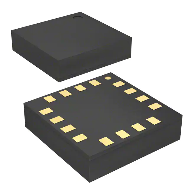
LPR5150ALTR is housed in a 5 mm × 5 mm × 1.5 mm plastic land grid array (LGA-16) package with bottom-side solder pads and no leads-designed for automated reflow assembly and high thermal/mechanical reliability in compact motion modules.
| Pin/Terminal | Circuit Role | Design Meaning |
|---|---|---|
| 1 GND | Ground reference | 0 V supply return for all analog and digital circuitry; must be low-impedance connection to minimize noise coupling |
| 2 FILTVDD | PLL filter node | Connection point for external RC network setting PLL loop dynamics; critical for driving frequency stability |
| 3 VCONT | PLL control voltage | Second PLL filter node; paired with FILTVDD to define phase margin and lock time of internal oscillator |
| 4 OUTY | Unamplified Y-axis output | Analog voltage proportional to roll rate (0.167 mV/°/s); requires external ADC or buffer for digitization |
| 5 4xINY | Y-axis 4× amplifier input | Accepts OUTY signal for internal amplification; short to GND/Vref if unamplified output used exclusively |
| 6 4xOUTY | Amplified Y-axis output | Buffered 4× gain output (0.67 mV/°/s); low-impedance drive capability eliminates need for external op-amp |
| 7 Vref | Internal reference voltage | Stable 1.23 V source used for zero-rate level and self-test biasing; decoupling capacitor required |
| 8 4xOUTX | Amplified X-axis output | Buffered 4× gain output for pitch rate; identical electrical behavior to 4xOUTY with independent signal path |
| 9 4xINX | X-axis 4× amplifier input | Accepts OUTX signal for internal amplification; tied to fixed voltage when only unamplified outputs are used |
| 10 OUTX | Unamplified X-axis output | Analog voltage proportional to pitch rate (0.167 mV/°/s); matches OUTY in sensitivity and offset characteristics |
| 11 ST | Self-test enable | Logic-high (≥0.8×Vdd) activates electrostatic test force; output shift confirms mechanical integrity and signal chain functionality |
| 12 PD | Power-down control | Logic-high (≥0.8×Vdd) reduces current to ≤5 µA; retains configuration state for fast wake-up in motion-triggered systems |
| 13 HP | High-pass filter reset | Pulse-high resets external HP filter capacitor; prevents DC saturation during rapid orientation changes or startup |
| 14,15 Res | Reserved | Must be connected to Vdd; no internal function but required for mechanical and thermal stability of LGA structure |
| 16 Vdd | Supply voltage | 2.7–3.6 V main power; requires 100 nF ceramic + 10 µF bulk decoupling placed adjacent to pin for noise immunity |
Key Features
| Feature | Design Value |
|---|---|
| Dual-axis analog rate outputs | Independent X/Y channels with selectable 1× or 4× gain per axis-enables flexible signal chain design without multiplexing or external gain stages |
| Embedded self-test | Electrostatic actuation verifies mechanical resonance and readout electronics in <10 ms-eliminates need for external test fixtures in production line testing |
| Integrated PLL timing | On-chip phase-locked loop synchronizes drive and sense frequencies-removes requirement for external clock sources or crystal oscillators |
| Low-power active mode | 6.8 mA typical supply current at 3 V-supports >100-hour battery life in Bluetooth game controllers with intermittent motion sampling |
| Robust LGA-16 packaging | 5×5×1.5 mm land grid array qualified to JEDEC J-STD-020C-enables high-volume SMT assembly and withstands >10,000 g mechanical shock |
Applications
| Gaming Motion Controllers | Industrial Robotic Joint Sensing |
|---|---|
|
Use Scenario: Wireless gamepad detecting tilt, rotation, and gesture for immersive gameplay. IC Role / Device Role / Timing Role: Dual-axis angular rate sensor providing real-time pitch/roll data to MCU for motion-to-action mapping. Use Value: 140 Hz bandwidth captures fast wrist flicks; 4× amplified outputs interface directly with 12-bit SAR ADCs without external gain stages. |
Use Scenario: Compact joint module monitoring angular velocity in collaborative robot arms. IC Role / Device Role / Timing Role: MEMS gyroscope delivering calibrated analog rate signals for closed-loop servo control feedback. Use Value: ±1500°/s full scale covers aggressive joint motion; -40 °C to +85 °C rating ensures operation inside sealed motor housings. |
| Pointing Devices & Remote Controls | Condition Monitoring Systems |
|
Use Scenario: Air mouse enabling cursor navigation via hand movement in smart TV interfaces. IC Role / Device Role / Timing Role: Low-latency motion sensor feeding analog outputs to ultra-low-power MCU for gesture classification. Use Value: 6.8 mA active current and 1–5 µA power-down mode extend coin-cell battery life to >6 months in intermittent-use devices. |
Use Scenario: Vibration-sensitive equipment monitoring rotational instability in HVAC actuators or conveyor drives. IC Role / Device Role / Timing Role: High-shock survivable angular rate detector identifying abnormal torsional oscillations before mechanical failure. Use Value: 10,000 g shock rating ensures reliability in high-vibration industrial environments; zero-rate stability minimizes false alarms over temperature cycles. |
Equivalent & Alternatives
The following parts are listed as comparable options for similar dual-axis analog gyroscope applications.
| Alternative Part | Technical Difference | Application Difference | Selection Advice |
|---|---|---|---|
| ADXRS649 | Single-axis, 2000°/s range, SPI digital output; higher noise density (0.015°/s/√Hz) | Requires microcontroller with SPI interface and digital filtering; lacks dual-axis integration | Select when digital interface and higher full-scale range outweigh need for analog simplicity and dual-axis parallel outputs |
| MPU-6050 | 6-axis IMU (3-axis gyro + 3-axis accel), I²C digital output, integrated DMP processor | Delivers fused orientation data but adds software complexity; gyro bandwidth limited to 100 Hz in default mode | Select when attitude estimation (pitch/roll/yaw) is required and system has processing resources for sensor fusion algorithms |
Compared with ADXRS649 and MPU-6050, the LPR5150ALTR offers native dual-axis analog outputs with minimal external components, lower latency than digital IMUs, and superior shock resilience-making it optimal for cost-sensitive, low-power motion controllers where analog signal chain simplicity is prioritized.
Availability
LPR5150ALTR is available at Aetrix Electronics and suitable for gaming peripherals, industrial robotics, pointing devices, and condition monitoring systems requiring stable component supply across long production lifecycles.
Supply support for LPR5150ALTR includes scheduled delivery planning, volume procurement assistance, BOM continuity management, traceable sourcing, and lifecycle availability coordination for OEM customers, industrial embedded developers, connected-device designers, and electronics production programs.
Manufacturer
STMicroelectronics is a global semiconductor leader headquartered in Geneva, Switzerland, specializing in MEMS sensors, microcontrollers, and power management ICs with over 30 years of automotive and industrial qualification experience.
The LPR5150ALTR belongs to ST's high-stability analog gyroscope product line, designed specifically for motion-sensing applications demanding precision angular rate measurement without digital overhead or complex calibration.
FAQ
What is the purpose of the HP pin on the LPR5150ALTR?
The HP (High Pass Filter Reset) pin allows external reset of an optional high-pass filter capacitor connected to the output. When driven high, it discharges the capacitor to prevent DC saturation during rapid orientation changes or power-on initialization-ensuring accurate baseline recovery before motion tracking begins.
How does the self-test function verify sensor integrity?
The ST pin activates an electrostatic test force that displaces the micromachined driving mass, generating a known Coriolis-equivalent output shift (~1.0 V at 3 V supply). Measuring this shift on OUTX/OUTY or 4xOUTX/4xOUTY confirms both mechanical resonance and analog signal chain functionality without external motion sources.
Can the LPR5150ALTR operate without external filtering components?
Yes-the device includes an embedded low-pass filter with 140 Hz cutoff. However, external RC networks on FILTVDD and VCONT pins are mandatory for PLL stabilization, and shorting 4xINX to GND/Vref or 4xINY to GND/Vref is required when using only unamplified outputs to prevent floating inputs and ensure proper biasing.
Why does the LPR5150ALTR use an LGA-16 package instead of QFN or SOIC?
The LGA-16 package provides superior mechanical coupling between the MEMS die and PCB, minimizing stress-induced zero-rate drift. Its bottom-terminal layout enables shorter bond wires and better thermal dissipation-critical for maintaining angular rate accuracy across temperature gradients in compact motion modules.
LPR5150ALTR Specifications
- Product attributes
- Attribute value
- Manufacturer:
- STMicroelectronics
- Series:
- -
- Package/Case:
- 16-LFLGA
- Packaging:
- Tape & Reel (TR)
- Product Status:
- Obsolete
- Type:
- Analog
- Axis:
- X (Pitch), Y (Roll)
- Range °/s:
- ±1500
- Sensitivity (LSB/(°/s)):
- -
- Sensitivity (mV/°/s):
- 0.67
- Bandwidth:
- 140Hz
- Output Type:
- Analog Voltage
- Voltage - Supply:
- 2.7V ~ 3.6V
- Current - Supply:
- 6.8 mA
- Features:
- -
- Operating Temperature:
- -40°C ~ 85°C
- Grade:
- -
- Qualification:
- -
LPR5150ALTR FAQ
1.How can I place an order for LPR5150ALTR through Aetrix?
Please submit a Request for Quotation (RFQ) for LPR5150ALTR on Aetrix. Our sales agent will provide a competitive quotation and guide you through the order confirmation once you accept the terms.
2.Are the price and stock information for LPR5150ALTR reliable?
The price and inventory of LPR5150ALTR are updated periodically and may fluctuate due to market conditions. Stock and pricing data are typically refreshed every 24 hours. Quotation validity for LPR5150ALTR is usually 5 days.
3.What payment methods are accepted for LPR5150ALTR?
We accept Wire Transfer, PayPal, Credit Card, Western Union, MoneyGram, and Escrow for LPR5150ALTR transactions.
Note: Certain payment methods may incur a processing fee.
4.How is shipping managed for LPR5150ALTR?
LPR5150ALTR orders can be shipped via leading logistics carriers, including DHL, UPS, FedEx, TNT, or Registered Mail.
Once your LPR5150ALTR order is processed, you will receive an email with the shipment details and tracking number.
Note: Tracking information may take up to 24 hours to appear. Express delivery typically takes 3–5 business days.
5.How can I obtain technical support or documentation for LPR5150ALTR?
For technical support, including LPR5150ALTR datasheets, pinout diagrams, or application guidance, please contact our engineering support team. They can provide detailed documentation and assistance for your LPR5150ALTR requirements.
6.How does Aetrix verify that LPR5150ALTR is sourced from the original manufacturer or authorized distributors?
All LPR5150ALTR products on Aetrix are procured from qualified distributors and authorized channels. Our dedicated quality assurance team conducts strict verification, including traceability checks and, if necessary, third-party testing. This ensures that LPR5150ALTR meets industry standards.
7.What is the process for return or replacement of LPR5150ALTR?
All LPR5150ALTR units undergo pre-shipment inspection (PSI). If there is an issue with LPR5150ALTR, returns or replacements are accepted under the following conditions:
1.Quantity discrepancies, incorrect items, or visible external defects (such as breakage or corrosion), acknowledged by Aetrix.
2.The issue is reported within 90 days of delivery.
3.The LPR5150ALTR part is unused and in its original packaging.
Return procedure for LPR5150ALTR:
1.Submit a request within 90 days.
2.Obtain a Return Material Authorization (RMA) from Aetrix.
LPR5150ALTR Tags
-
I3G4250DTR
STMicroelectronics

-
IAM-20380HT
TDK InvenSense

-
IAM-20380
TDK InvenSense
-
A3G4250DTR
STMicroelectronics
-
SCR2100-D08-05
Murata Electronics
-
ADXRS623BBGZ-RL
Analog Devices Inc.
-
ADXRS624BBGZ-RL
Analog Devices Inc.
-
ADXRS620BBGZ-RL
Analog Devices Inc.
-
ADXRS642BBGZ-RL
Analog Devices Inc.
-
ADXRS450BEYZ
Analog Devices Inc.
-
ADXRS453BRGZ
Analog Devices Inc.
-
ADXRS649BBGZ
Analog Devices Inc.
Tech Hub

A practical engineering and sourcing framework covering lifecycle verification, lifetime-buy calculations, replacement qualification, supplier checks and counterfeit-risk controls.

TTL and CMOS logic families differ in thresholds, loading, output drive, power and timing. This engineering guide compares 74HC and 74HCT, calculates noise margins and checks 3.3 V/5 V compatibility.

A practical engineering guide to 3.3V and 5V logic compatibility, input thresholds, resistor dividers, translator ICs, MOSFET level shifting, I2C pull-ups, timing limits and power-sequencing risks.

The 74HC595 uses push-pull logic outputs, while the TPIC6B595 uses 50 V open-drain DMOS sinks for higher-power loads. This guide compares timing, current limits, 3.3 V interfacing, load wiring, thermal…

The 74HC595 converts serial data into eight stable parallel outputs. This guide covers pin functions, shift and storage timing, OE and MR behavior, drive-current limits, cascading, voltage compatibilit…

A technical comparison of level-sensitive latches and edge-triggered flip-flops, covering timing windows, setup and hold limits, master–slave operation, time borrowing, race-through, HDL inference and…

A D latch stores one bit while Enable controls when data can pass. This reference covers gate-level operation, truth tables, transparency, setup and hold timing, LE versus OE, common ICs and practical …

An SR latch stores one bit through cross-coupled feedback. This engineering reference covers NOR and NAND implementations, truth tables, forbidden-state recovery, gated operation, switch debouncing, fa…

Latch circuits retain one bit through feedback. This technical reference covers SR and D latches, truth tables, transparency, timing limits, latch-versus-flip-flop behavior, applications and common log…

An engineering guide to LED driver operation, constant-current and constant-voltage outputs, linear and switching topologies, dimming, IC selection, calculations, replacement compatibility, and fault c…


