
 My Inquiry
 My Account


STMicroelectronics LY530AL
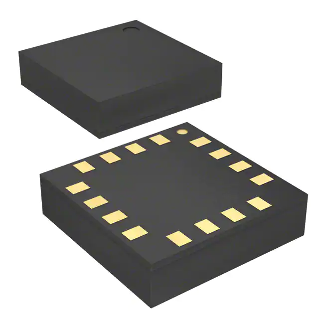
- Part No.:
- LY530AL
- Manufacturer:
- STMicroelectronics
- Category:
- Gyroscopes
- Package:
- 16-LFLGA
- Datasheet:
-
 LY530AL.pdf
- Description:
- IC MEMS INERTL SENSOR SGL 16LGA
- Quantity:
- Payment:

- Shipping:

Inventory:4,583
Please send an inquiry. Send us your inquiry, and we will respond immediately.
Product details
Overview
LY530AL from STMicroelectronics is a single-axis MEMS yaw rate gyroscope delivering ±300°/s full-scale analog output and I²C/SPI digital output, operating from 2.7 V to 3.6 V with 4.8 mA analog supply current and 88 Hz −3 dB bandwidth at CACT = 10 nF, used in image stabilization for digital cameras and motion-controlled human-machine interfaces.
For engineers reviewing the LY530AL datasheet, LY530AL pinout, LY530AL application, or LY530AL equivalent, this page provides verified pin functions, real-world use scenarios, confirmed alternative parts with documented interface and sensitivity differences, and supply support for industrial embedded and consumer electronics design programs.
Technical Context
The LY530AL integrates a micromachined silicon sensing element with a CMOS interface IC, featuring dual-output architecture: absolute analog voltage output referenced to VDDA/2 (1.65 V zero-rate level) and configurable digital output via I²C or SPI with programmable low-pass and high-pass filters. Its PLL-based demodulation and active phase-switched filter enable stable rate measurement from DC to 88 Hz.
It supports embedded self-test (300 mV analog output shift), power-down mode (1 µA quiescent current), and operates across −40 °C to +85 °C. Digital output resolution is 1.55 LSB/°/s at 1 kHz ODR, with register-mapped control of filtering, output selection, and status monitoring.
Key Specifications
| Parameter | Value and Actual Design Meaning |
|---|---|
| Full Scale Range | ±300°/s - defines maximum measurable yaw rotation rate without clipping |
| Analog Sensitivity | 3.3 mV/°/s - enables direct voltage-to-rate conversion with 0.3°/s resolution at 1 mV LSB |
| −3 dB Bandwidth | 88 Hz (CACT = 10 nF) - sets usable dynamic response limit for motion tracking |
| Digital Output Rate | 1 kHz - supports real-time motion control loops with ≤1 ms latency |
| Supply Current (Analog) | 4.8 mA - determines power budget for always-on analog path in battery-powered devices |
| Power-Down Current | 1 µA - enables ultra-low-power sleep states during idle periods |
| Operating Temperature | −40 °C to +85 °C - qualifies for automotive cabin and industrial edge environments |
Pinout & Package
LY530AL uses a 5 mm × 5 mm × 1.5 mm LGA-16 package with exposed pad for thermal and mechanical stability. Pin assignment is validated per ST's official pin description table (Rev 1, p.7).
| Pin/Terminal | Circuit Role | Design Meaning |
|---|---|---|
| 1, 2 FILTVDD / VCONT | PLL filter connection | Set PLL loop dynamics; external RC network determines clock stability and jitter performance |
| 3 CACT | Active low-pass filter capacitor | Configures −3 dB bandwidth (e.g., 10 nF → 88 Hz); critical for noise vs. response trade-off |
| 4 ANALOG OUTPUT | Analog rate signal output | DC-coupled voltage output (0.4–2.9 V swing) with 1.65 V zero-rate offset; requires no external ADC |
| 6 GND | Ground reference | Common return for analog and digital sections; must be low-impedance to minimize crosstalk |
| 7 ST | Self-test control input | Logic high triggers internal mechanical excitation; verifies sensor integrity without external motion |
| 8 PD | Power-down enable | Logic high places device in 1 µA standby; essential for duty-cycled operation in portable systems |
| 9 SCL/SPC | I²C clock / SPI clock | Shared pin: SCL in I²C mode (max 400 kHz), SPC in SPI mode (max 10 MHz) |
| 10 CS | SPI chip select / I²C mode select | Low = SPI enabled; high = I²C enabled; determines interface protocol at power-up |
| 11 DR | DataReady indicator | Open-drain output pulses when new digital sample is ready; synchronizes host read timing |
| 13 SDA_SDI_SDO | I²C data / SPI input / 3-wire output | Tri-function pin: bidirectional I²C data, SPI SDI (4-wire), or SDO (3-wire); requires mode-aware routing |
| 14 Res | Internal pull-up enable | Must be tied to Vdd to activate internal pull-ups on CS, SCL/SPC, and SDA_SDI_SDO |
| 15 VDDD | Digital supply | Separate 2.7–3.6 V rail for digital logic and interface; decoupling required near pin |
| 16 VDDA | Analog supply | Independent 2.7–3.6 V rail for sensing and analog conditioning; isolation prevents digital noise coupling |
Key Features
| Feature | Design Value |
|---|---|
| Dual analog + digital output | Enables hybrid system architectures: analog for low-latency feedback, digital for configuration and diagnostics |
| Programmable filtering | Independent low-pass (via CACT) and high-pass (register-configurable) filters allow custom motion bandpass tuning |
| Embedded self-test | Validates MEMS structure and signal chain integrity in-system without external stimulus or calibration equipment |
| High shock survivability | Rated for 10,000 g / 0.1 ms shocks - ensures reliability in handheld, robotic, and vehicular mounting |
| ECOPACK® RoHS compliance | Meets EU RoHS Directive 2011/65/EU and halogen-free requirements for green manufacturing and end-of-life handling |
Applications
| Image Stabilization | Motion-Controlled HMI |
|---|---|
|
Use Scenario: Compensating hand tremor in digital still cameras and camcorders by feeding real-time yaw rate into lens-shift actuators. IC Role / Device Role / Timing Role: Primary yaw axis sensor providing analog output with <300 ms start-up time and 88 Hz bandwidth for sub-pixel correction. Use Value: Enables optical image stabilization (OIS) without external ADC or timing controller, reducing BOM count and latency. |
Use Scenario: Detecting head or controller rotation in VR gaming headsets and gesture-based remote controls. IC Role / Device Role / Timing Role: Motion input transducer delivering 1 kHz digital samples via I²C to MCU for real-time pose estimation. Use Value: Supports sub-10 ms motion-to-display latency using DR interrupt and register-mapped filtering to suppress low-frequency drift. |
| GPS-Aided Navigation | Robotics Platform Stabilization |
|
Use Scenario: Augmenting GPS heading updates in urban canyons where satellite signals are intermittent or degraded. IC Role / Device Role / Timing Role: Dead-reckoning yaw sensor fusing analog rate output with IMU fusion algorithms during GPS outages. Use Value: Maintains heading accuracy within ±2° over 30 s GPS dropout using factory-trimmed 3.3 mV/°/s sensitivity and low tempco (4% over −40 to +85 °C). |
Use Scenario: Stabilizing mobile robot chassis or robotic arm base against terrain-induced yaw disturbances. IC Role / Device Role / Timing Role: Feedback element in closed-loop yaw control loop, interfaced via SPI for deterministic timing and low-jitter sampling. Use Value: Enables robust navigation in unstructured environments using self-test verification before mission start and 1 µA power-down between maneuvers. |
Equivalent & Alternatives
The following parts are listed as comparable options for similar single-axis yaw rate gyroscope applications.
| Alternative Part | Technical Difference | Application Difference | Selection Advice |
|---|---|---|---|
| LSM6DS3TR-C | 6-axis IMU (3-axis gyro + 3-axis accel); digital-only output; 110 Hz gyro BW; 1.8 V supply | Requires external processing for gyro-only use; lacks analog output and self-test voltage shift | Select when multi-axis fusion is needed and analog interface is unnecessary |
| ADXRS649 | Single-axis gyro; analog-only output; ±300°/s FS; 2.7–5.25 V supply; 120 Hz BW; higher noise floor (0.012°/s/√Hz) | No digital interface or embedded self-test; larger SOIC package (8.7 × 7.0 mm) | Select for legacy analog systems requiring wider supply range and higher bandwidth, accepting larger footprint |
Compared with LY530AL, LSM6DS3TR-C adds acceleration sensing but removes analog output and self-test voltage verification, while ADXRS649 offers higher bandwidth and supply flexibility but lacks digital configurability and compact LGA packaging.
Availability
LY530AL is available at Aetrix Electronics and suitable for image stabilization, motion-controlled HMI, GPS-aided navigation, and robotics platform stabilization requiring stable component supply across extended temperature ranges and long-lifecycle designs.
Supply support for LY530AL includes scheduled delivery planning, volume procurement assistance, BOM continuity management, traceable sourcing, and lifecycle availability coordination for OEM customers, industrial embedded developers, connected-device designers, and electronics production programs.
Manufacturer
STMicroelectronics is a global semiconductor leader headquartered in Geneva, Switzerland, designing and manufacturing microcontrollers, sensors, power ICs, and analog components for industrial, automotive, and consumer markets.
The LY530AL belongs to ST's MEMS inertial sensor product line, engineered specifically for cost-sensitive, low-power motion-sensing applications requiring analog immediacy and digital configurability in compact form factors.
FAQ
What is the function of the CACT pin on LY530AL?
The CACT pin connects an external capacitor (typically 10 nF) to set the −3 dB bandwidth of the analog low-pass filter. This capacitor directly determines the cutoff frequency-e.g., 10 nF yields 88 Hz-enabling designers to balance motion responsiveness against noise rejection without firmware changes or external op-amps.
How does the LY530AL self-test feature operate?
The ST pin triggers an internal electrostatic actuation that mechanically excites the MEMS structure, producing a calibrated 300 mV shift in the ANALOG OUTPUT voltage (or 230 LSB change in digital output). This verifies both sensor element integrity and analog/digital signal chain functionality without external motion or calibration fixtures.
Can LY530AL operate with only analog output enabled?
Yes. The analog output remains fully functional regardless of digital interface state. When CS is held high (I²C mode) and no I²C/SPI transactions occur, the device delivers continuous analog rate data with 1.65 V zero-rate level and 3.3 mV/°/s sensitivity, drawing only 4.8 mA-ideal for simple feedback loops without microcontroller overhead.
What is the significance of separate VDDA and VDDD pins?
VDDA powers the MEMS sensing element and analog signal conditioning circuitry, while VDDD supplies the digital interface and logic. This separation minimizes digital switching noise coupling into the sensitive analog path, preserving 0.8% full-scale nonlinearity and enabling reliable sub-degree-per-second resolution in electrically noisy environments.
LY530AL Specifications
- Product attributes
- Attribute value
- Manufacturer:
- STMicroelectronics
- Series:
- -
- Package/Case:
- 16-LFLGA
- Packaging:
- Tray
- Product Status:
- Obsolete
- Type:
- Analog
- Axis:
- X (Pitch)
- Range °/s:
- ±300
- Sensitivity (LSB/(°/s)):
- -
- Sensitivity (mV/°/s):
- 33.3
- Bandwidth:
- 88Hz
- Output Type:
- Analog Voltage
- Voltage - Supply:
- 2.7V ~ 3.6V
- Current - Supply:
- 4.8 mA
- Features:
- -
- Operating Temperature:
- -40°C ~ 85°C
- Grade:
- -
- Qualification:
- -
LY530AL FAQ
1.How can I place an order for LY530AL through Aetrix?
Please submit a Request for Quotation (RFQ) for LY530AL on Aetrix. Our sales agent will provide a competitive quotation and guide you through the order confirmation once you accept the terms.
2.Are the price and stock information for LY530AL reliable?
The price and inventory of LY530AL are updated periodically and may fluctuate due to market conditions. Stock and pricing data are typically refreshed every 24 hours. Quotation validity for LY530AL is usually 5 days.
3.What payment methods are accepted for LY530AL?
We accept Wire Transfer, PayPal, Credit Card, Western Union, MoneyGram, and Escrow for LY530AL transactions.
Note: Certain payment methods may incur a processing fee.
4.How is shipping managed for LY530AL?
LY530AL orders can be shipped via leading logistics carriers, including DHL, UPS, FedEx, TNT, or Registered Mail.
Once your LY530AL order is processed, you will receive an email with the shipment details and tracking number.
Note: Tracking information may take up to 24 hours to appear. Express delivery typically takes 3–5 business days.
5.How can I obtain technical support or documentation for LY530AL?
For technical support, including LY530AL datasheets, pinout diagrams, or application guidance, please contact our engineering support team. They can provide detailed documentation and assistance for your LY530AL requirements.
6.How does Aetrix verify that LY530AL is sourced from the original manufacturer or authorized distributors?
All LY530AL products on Aetrix are procured from qualified distributors and authorized channels. Our dedicated quality assurance team conducts strict verification, including traceability checks and, if necessary, third-party testing. This ensures that LY530AL meets industry standards.
7.What is the process for return or replacement of LY530AL?
All LY530AL units undergo pre-shipment inspection (PSI). If there is an issue with LY530AL, returns or replacements are accepted under the following conditions:
1.Quantity discrepancies, incorrect items, or visible external defects (such as breakage or corrosion), acknowledged by Aetrix.
2.The issue is reported within 90 days of delivery.
3.The LY530AL part is unused and in its original packaging.
Return procedure for LY530AL:
1.Submit a request within 90 days.
2.Obtain a Return Material Authorization (RMA) from Aetrix.
LY530AL Tags
-
I3G4250DTR
STMicroelectronics

-
IAM-20380HT
TDK InvenSense

-
IAM-20380
TDK InvenSense
-
A3G4250DTR
STMicroelectronics
-
SCR2100-D08-05
Murata Electronics
-
ADXRS623BBGZ-RL
Analog Devices Inc.
-
ADXRS624BBGZ-RL
Analog Devices Inc.
-
ADXRS620BBGZ-RL
Analog Devices Inc.
-
ADXRS642BBGZ-RL
Analog Devices Inc.
-
ADXRS450BEYZ
Analog Devices Inc.
-
ADXRS453BRGZ
Analog Devices Inc.
-
ADXRS649BBGZ
Analog Devices Inc.
Tech Hub

A practical engineering and sourcing framework covering lifecycle verification, lifetime-buy calculations, replacement qualification, supplier checks and counterfeit-risk controls.

TTL and CMOS logic families differ in thresholds, loading, output drive, power and timing. This engineering guide compares 74HC and 74HCT, calculates noise margins and checks 3.3 V/5 V compatibility.

A practical engineering guide to 3.3V and 5V logic compatibility, input thresholds, resistor dividers, translator ICs, MOSFET level shifting, I2C pull-ups, timing limits and power-sequencing risks.

The 74HC595 uses push-pull logic outputs, while the TPIC6B595 uses 50 V open-drain DMOS sinks for higher-power loads. This guide compares timing, current limits, 3.3 V interfacing, load wiring, thermal…

The 74HC595 converts serial data into eight stable parallel outputs. This guide covers pin functions, shift and storage timing, OE and MR behavior, drive-current limits, cascading, voltage compatibilit…

A technical comparison of level-sensitive latches and edge-triggered flip-flops, covering timing windows, setup and hold limits, master–slave operation, time borrowing, race-through, HDL inference and…

A D latch stores one bit while Enable controls when data can pass. This reference covers gate-level operation, truth tables, transparency, setup and hold timing, LE versus OE, common ICs and practical …

An SR latch stores one bit through cross-coupled feedback. This engineering reference covers NOR and NAND implementations, truth tables, forbidden-state recovery, gated operation, switch debouncing, fa…

Latch circuits retain one bit through feedback. This technical reference covers SR and D latches, truth tables, transparency, timing limits, latch-versus-flip-flop behavior, applications and common log…

An engineering guide to LED driver operation, constant-current and constant-voltage outputs, linear and switching topologies, dimming, IC selection, calculations, replacement compatibility, and fault c…


