
 My Inquiry
 My Account


Microchip Technology MCP2030A-I/P
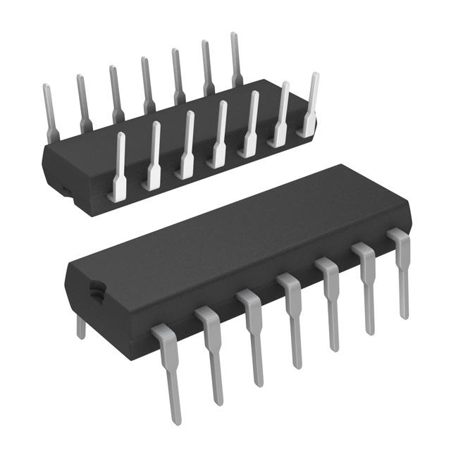
- Part No.:
- MCP2030A-I/P
- Manufacturer:
- Microchip Technology
- Category:
- RFID, RF Access, Monitoring ICs
- Package:
- 14-DIP (0.300", 7.62mm)
- Datasheet:
-
 MCP2030A-I/P.pdf
- Description:
- IC PEPS/TPMS 125KHZ 14DIP
- Quantity:
- Payment:

- Shipping:

Inventory:141
Please send an inquiry. Send us your inquiry, and we will respond immediately.
Product details
Overview
MCP2030A-I/P from Microchip Technology is a three-channel low-frequency (125 kHz) analog front-end IC for bidirectional LF transponder communication, featuring 1 mVPP input sensitivity, programmable 63 pF antenna tuning per channel, and SPI-configurable output modes (demodulated data, carrier clock, or RSSI current). It enables battery-constrained automotive PKE and TPMS initiator systems with ultra-low standby current (4 µA, 3 channels enabled) and industrial temperature operation (–40°C to +85°C).
For engineers reviewing the MCP2030A-I/P datasheet, MCP2030A-I/P pinout, MCP2030A-I/P application, or MCP2030A-I/P equivalent, this page delivers verified technical context on LF signal demodulation, RSSI linearity, output enable filter timing, AGC stabilization, and SPI register configuration - all critical for transponder initiator design, antenna tuning validation, and low-power wake-up architecture.
Technical Context
The MCP2030A-I/P implements a high-gain, low-noise analog signal path with RF limiter (RFLM), automatic gain control (AGC), and demodulator stages optimized for 125 kHz carrier detection. Its three independent LC input channels (LCX/LCY/LCZ) support orthogonal antenna placement and individual enable/disable via Configuration Register 0.
Demodulated output appears on LFDATA/CCLK/SDIO with configurable timing: AGC stabilization time (TSTAB = 4 ms typical), demodulator charge/discharge delays (TDR/TDF = 50 µs each), and programmable output enable filters (TOEH/TOEL from 1–4 ms) that enforce valid pulse timing before releasing demodulated data - essential for noise-immune wake-up in automotive environments.
Key Specifications
| Parameter | Value and Actual Design Meaning |
|---|---|
| Input Carrier Frequency | 125 kHz typical - matches ISO 11784/11785 LF transponder standards and enables interoperability with passive RFID tags. |
| Input Sensitivity | 1 mVPP min - detects weak signals from distant or misaligned LF antennas without external amplification. |
| Minimum Modulation Depth | 8% - supports reliable demodulation of low-depth amplitude-modulated signals common in batteryless transponders. |
| Standby Current | 4 µA (3 channels enabled) - extends battery life in always-on initiator nodes such as door handle sensors. |
| RSSI Output Linearity | ±15% over 0–4 VPP input - enables accurate distance estimation and signal quality monitoring in access control systems. |
| Tuning Capacitance Range | 0–63 pF per channel (1 pF/step) - allows precise LC resonance calibration across manufacturing tolerances and temperature drift. |
| SPI Clock Frequency | Up to 3 MHz - permits fast register read/write during system initialization or dynamic reconfiguration. |
Pinout & Package
The MCP2030A-I/P is packaged in a 14-pin PDIP (Plastic Dual In-line Package) with 0.300-inch body width and through-hole mounting. Pin 1 is located at the left end of the top row when viewed with the notch facing up.
| Pin/Terminal | Circuit Role | Design Meaning |
|---|---|---|
| 1, 14 | VSS | Ground reference for analog/digital circuitry; dual pins reduce ground impedance and improve noise immunity. |
| 2 | CS | Digital input controlling SPI mode (CS low) vs. normal operation (CS high); open-drain with internal pull-up. |
| 3 | SCLK/ALERT | Time-shared pin: SPI clock input when CS low; open-drain ALERT output (low on parity error or alarm timeout) when CS high. |
| 4 | RSSI | Current-sink output proportional to input signal strength; requires external pull-up resistor for voltage-level interface. |
| 5, 12 | NC | No-connect pins - must remain unconnected to avoid parasitic coupling or latch-up risk. |
| 6 | LFDATA/CCLK/SDIO | Time-shared I/O: demodulated data or carrier clock output (CS high); SPI data I/O (CS low); bidirectional with internal logic control. |
| 7, 8 | VDD | Positive supply (2.0–3.6 V); dual pins support stable power delivery and decoupling capacitor placement. |
| 9, 10, 11 | LCZ, LCY, LCX | High-impedance analog inputs for LC resonant antennas; each supports independent enable/disable and tuning capacitor programming. |
| 13 | LCCOM | Common reference node for all three LC antennas; connects to ground or bias point depending on antenna topology. |
Key Features
| Feature | Design Value |
|---|---|
| Three independent LC input channels | Enables omnidirectional signal detection using orthogonally mounted antennas - critical for hands-free PKE entry without user orientation. |
| Programmable output enable filter | Nine timing configurations (TOEH/TOEL = 1–4 ms) reject short-duration noise pulses while passing valid transponder bursts - eliminates false wake-ups. |
| Bidirectional LF talk-back capability | Clamp-on/clamp-off commands modulate antenna voltage to transmit back to transponder - enables full-duplex initiator functionality in TPMS and immobilizer systems. |
| Low-power operating modes | Sleep (0.2 µA), Standby (4 µA), and Active (13 µA) states allow adaptive power management aligned with vehicle door event timing. |
| Internal RC oscillator | 32 kHz ±10% trimmed oscillator provides timing reference for AGC, inactivity timer, and alarm functions - eliminates need for external crystal. |
Applications
| Automotive Passive Keyless Entry (PKE) | Tire Pressure Monitoring System (TPMS) Initiator |
|---|---|
|
Use Scenario: Driver approaches vehicle; door handle sensor initiates LF field to wake and authenticate transponder key fob. IC Role / Device Role / Timing Role: MCP2030A-I/P acts as the LF initiator AFE, detecting modulated response from key fob and providing RSSI-based proximity feedback. Use Value: 1 mVPP sensitivity enables >1.5 m detection range; programmable tuning compensates for antenna detuning due to metal housing. |
Use Scenario: Vehicle ignition triggers LF burst to interrogate tire-mounted TPMS sensors and retrieve pressure/temperature data. IC Role / Device Role / Timing Role: MCP2030A-I/P generates controlled 125 kHz field, receives backscatter-modulated reply, and outputs demodulated data to MCU via SPI. Use Value: 8% minimum modulation depth support ensures robust reception from low-battery TPMS units; clamp-on command enables active sensor interrogation. |
| Engine Immobilizer Antenna Module | Long-Range Access Control Transponder |
|
Use Scenario: Ignition key inserted into column; embedded LF antenna verifies cryptographic challenge-response with transponder chip. IC Role / Device Role / Timing Role: MCP2030A-I/P serves as secure initiator AFE, delivering precise carrier timing and validating response integrity via RSSI consistency checks. Use Value: ±15% RSSI linearity allows rejection of relay attacks based on anomalous signal strength; AGC stabilization time (4 ms) fits within immobilizer handshake window. |
Use Scenario: Parking gate or apartment entry system detects authorized transponder at 2–3 meter range using large-area LF loop antenna. IC Role / Device Role / Timing Role: MCP2030A-I/P operates in multi-channel mode with tuned LCZ/LCY inputs to maintain detection coverage across wide angular zones. Use Value: 63 pF per-channel tuning adjusts resonance for large-loop inductance (1–10 mH); low standby current (4 µA) enables solar/battery-powered installations. |
Equivalent & Alternatives
The following parts are listed as comparable options for similar LF analog front-end applications.
| Alternative Part | Technical Difference | Application Difference | Selection Advice |
|---|---|---|---|
| TDK IAM-85003 | Single-channel, fixed 125 kHz carrier, no programmable tuning capacitors; RSSI output not available. | Limited to single-axis detection; lacks bidirectional talk-back and RSSI-based proximity estimation. | Select when cost-sensitive, single-antenna designs require minimal configuration and no RSSI feedback. |
| NXP UCODE I2C | Integrated NFC/RFID tag IC with built-in EEPROM; no LF initiator capability - operates only as transponder. | Functions exclusively as responder, not initiator; incompatible with PKE/TPMS initiator role. | Not a functional alternative; only relevant if redesigning system to use NFC-based authentication instead of LF. |
Compared with TDk IAM-85003 and NXP UCODE I2C, the MCP2030A-I/P uniquely combines triple-channel LF initiation, programmable antenna tuning, RSSI output, and bidirectional talk-back - making it the only viable option for automotive-grade, multi-axis, battery-efficient initiator modules requiring field strength feedback and transponder command capability.
Availability
MCP2030A-I/P is available at Aetrix Electronics and suitable for automotive PKE systems, TPMS initiator modules, engine immobilizer antennas, and long-range access control transponders requiring stable component supply, extended temperature compliance (–40°C to +85°C), and long-term lifecycle continuity.
Supply support for MCP2030A-I/P includes scheduled delivery planning, volume procurement assistance, BOM continuity management, traceable sourcing, and lifecycle availability coordination for OEM customers, industrial embedded developers, connected-device designers, and electronics production programs.
Manufacturer
Microchip Technology is a leading provider of microcontroller, analog, and mixed-signal semiconductor solutions, founded in 1989 and headquartered in Chandler, Arizona.
The MCP2030A-I/P belongs to Microchip's dedicated LF transponder AFE product line, designed specifically for ultra-low-power, high-sensitivity initiator applications in automotive security and wireless sensing systems.
FAQ
What is the primary function of the MCP2030A-I/P in a Passive Keyless Entry system?
The MCP2030A-I/P serves as the analog front-end initiator in Passive Keyless Entry systems, generating and receiving 125 kHz LF signals to detect and authenticate transponder keys. It provides demodulated data, carrier clock, or RSSI current output - enabling proximity sensing, secure challenge-response handshakes, and low-power wake-up. Its 1 mVPP sensitivity and programmable tuning ensure reliable operation across varying antenna geometries and environmental conditions in the final MCP2030A-I/P implementation.
How does the output enable filter in the MCP2030A-I/P improve noise immunity?
The MCP2030A-I/P's output enable filter enforces minimum high-time (TOEH) and low-time (TOEL) requirements on incoming LF pulses before releasing demodulated data on LFDATA. With nine programmable timing configurations (e.g., TOEH = 1–4 ms, TOEL = 1–4 ms), it rejects short-duration EMI bursts and spurious signals while passing valid transponder responses - directly preventing false wake-ups in electrically noisy automotive cabins. This behavior is confirmed in Figures 2-26 through 2-28 of the MCP2030A-I/P datasheet.
Can the MCP2030A-I/P operate without an external crystal or resonator?
Yes, the MCP2030A-I/P integrates a factory-trimmed 32 kHz internal RC oscillator used for AGC timing, inactivity alarms, and output enable filter clocks - eliminating the need for external timing components. This oscillator operates across the full industrial temperature range (–40°C to +85°C) with ±10% variation, as specified in the AC Characteristics table of the MCP2030A-I/P datasheet. No external crystal, resonator, or capacitor is required for basic operation.
What is the role of the LCCOM pin in the MCP2030A-I/P antenna interface?
The LCCOM pin serves as the common reference node for all three LC input channels (LCX, LCY, LCZ) in the MCP2030A-I/P. Each LC antenna is connected between its respective LC pin and LCCOM, forming a differential-like sensing structure that improves common-mode noise rejection. LCCOM may be tied to VSS (ground) or biased to an intermediate voltage depending on antenna topology - as defined in Section 3.7 of the MCP2030A-I/P datasheet - and must never be left floating to ensure proper RF limiter and AGC operation.
How does the MCP2030A-I/P support bidirectional communication with transponders?
The MCP2030A-I/P supports bidirectional LF communication via its clamp-on and clamp-off commands, which modulate the voltage across the connected LC antenna by switching internal transistors. This creates backscatter modulation detectable by the transponder, enabling initiator-initiated commands such as sensor polling or challenge transmission. The functionality is implemented through SPI-configured registers and documented in Figure 2-21 of the MCP2030A-I/P datasheet - distinguishing it from unidirectional receiver-only AFEs.
MCP2030A-I/P Specifications
- Product attributes
- Attribute value
- Manufacturer:
- Microchip Technology
- Series:
- -
- Package/Case:
- 14-DIP (0.300", 7.62mm)
- Packaging:
- Tube
- Product Status:
- Active
- Type:
- Passive Entry/Start, TPMS
- Frequency:
- 125kHz
- Standards:
- -
- Interface:
- SPI
- Voltage - Supply:
- 2V ~ 3.6V
- Operating Temperature:
- -40°C ~ 85°C
- Grade:
- -
- Qualification:
- -
- Mounting Type:
- Through Hole
- Supplier Device Package:
- 14-PDIP
MCP2030A-I/P FAQ
1.How can I place an order for MCP2030A-I/P through Aetrix?
Please submit a Request for Quotation (RFQ) for MCP2030A-I/P on Aetrix. Our sales agent will provide a competitive quotation and guide you through the order confirmation once you accept the terms.
2.Are the price and stock information for MCP2030A-I/P reliable?
The price and inventory of MCP2030A-I/P are updated periodically and may fluctuate due to market conditions. Stock and pricing data are typically refreshed every 24 hours. Quotation validity for MCP2030A-I/P is usually 5 days.
3.What payment methods are accepted for MCP2030A-I/P?
We accept Wire Transfer, PayPal, Credit Card, Western Union, MoneyGram, and Escrow for MCP2030A-I/P transactions.
Note: Certain payment methods may incur a processing fee.
4.How is shipping managed for MCP2030A-I/P?
MCP2030A-I/P orders can be shipped via leading logistics carriers, including DHL, UPS, FedEx, TNT, or Registered Mail.
Once your MCP2030A-I/P order is processed, you will receive an email with the shipment details and tracking number.
Note: Tracking information may take up to 24 hours to appear. Express delivery typically takes 3–5 business days.
5.How can I obtain technical support or documentation for MCP2030A-I/P?
For technical support, including MCP2030A-I/P datasheets, pinout diagrams, or application guidance, please contact our engineering support team. They can provide detailed documentation and assistance for your MCP2030A-I/P requirements.
6.How does Aetrix verify that MCP2030A-I/P is sourced from the original manufacturer or authorized distributors?
All MCP2030A-I/P products on Aetrix are procured from qualified distributors and authorized channels. Our dedicated quality assurance team conducts strict verification, including traceability checks and, if necessary, third-party testing. This ensures that MCP2030A-I/P meets industry standards.
7.What is the process for return or replacement of MCP2030A-I/P?
All MCP2030A-I/P units undergo pre-shipment inspection (PSI). If there is an issue with MCP2030A-I/P, returns or replacements are accepted under the following conditions:
1.Quantity discrepancies, incorrect items, or visible external defects (such as breakage or corrosion), acknowledged by Aetrix.
2.The issue is reported within 90 days of delivery.
3.The MCP2030A-I/P part is unused and in its original packaging.
Return procedure for MCP2030A-I/P:
1.Submit a request within 90 days.
2.Obtain a Return Material Authorization (RMA) from Aetrix.
MCP2030A-I/P Tags

-
SL2S2602FTBX
NXP Semiconductors

-
ST25DV04K-IER6S3
STMicroelectronics

-
ST25DV04K-IER6C3
STMicroelectronics
-
LXMSJZNCMD-217
Murata Electronics

-
NT3H2111W0FTTJ
NXP Semiconductors

-
NT3H2111W0FHKH
NXP Semiconductors

-
M24LR04E-RMC6T/2
STMicroelectronics
-
ST25DV04KC-JF6D3
STMicroelectronics

-
ST25DV64KC-IE6S3
STMicroelectronics

-
ST25DV64K-IER6T3
STMicroelectronics
-
NT3H2211W0FTTJ
NXP Semiconductors
-
NT3H2211W0FHKH
NXP Semiconductors
Tech Hub

TTL and CMOS logic families differ in thresholds, loading, output drive, power and timing. This engineering guide compares 74HC and 74HCT, calculates noise margins and checks 3.3 V/5 V compatibility.

A practical engineering guide to 3.3V and 5V logic compatibility, input thresholds, resistor dividers, translator ICs, MOSFET level shifting, I2C pull-ups, timing limits and power-sequencing risks.

The 74HC595 uses push-pull logic outputs, while the TPIC6B595 uses 50 V open-drain DMOS sinks for higher-power loads. This guide compares timing, current limits, 3.3 V interfacing, load wiring, thermal…

The 74HC595 converts serial data into eight stable parallel outputs. This guide covers pin functions, shift and storage timing, OE and MR behavior, drive-current limits, cascading, voltage compatibilit…

A technical comparison of level-sensitive latches and edge-triggered flip-flops, covering timing windows, setup and hold limits, master–slave operation, time borrowing, race-through, HDL inference and…

A D latch stores one bit while Enable controls when data can pass. This reference covers gate-level operation, truth tables, transparency, setup and hold timing, LE versus OE, common ICs and practical …

An SR latch stores one bit through cross-coupled feedback. This engineering reference covers NOR and NAND implementations, truth tables, forbidden-state recovery, gated operation, switch debouncing, fa…

Latch circuits retain one bit through feedback. This technical reference covers SR and D latches, truth tables, transparency, timing limits, latch-versus-flip-flop behavior, applications and common log…

An engineering guide to LED driver operation, constant-current and constant-voltage outputs, linear and switching topologies, dimming, IC selection, calculations, replacement compatibility, and fault c…

Operational amplifier guide covering op amp basics, feedback, ideal vs real op amps, common configurations, buffer circuits, offset, bias current, gain-bandwidth, slew rate, rail-to-rail limits and sel…


