
 My Inquiry
 My Account


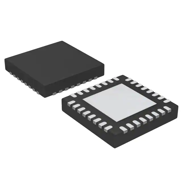
NXP Semiconductors MFRC52201HN1,151
- Part No.:
- MFRC52201HN1,151
- Manufacturer:
- NXP Semiconductors
- Category:
- RFID, RF Access, Monitoring ICs
- Package:
- 32-VFQFN Exposed Pad
- Datasheet:
-
 MFRC52201HN1,151.pdf
- Description:
- IC RFID READER 13.56MHZ 32HVQFN
- Quantity:
- Payment:

- Shipping:

Inventory:2,822
Please send an inquiry. Send us your inquiry, and we will respond immediately.
Product details
Overview
MFRC52201HN1,151 from NXP Semiconductors is a contactless 13.56 MHz reader/writer IC supporting ISO/IEC 14443 A/MIFARE and NTAG protocols, with SPI/I²C/UART host interfaces, 64-byte FIFO buffer, and integrated analog front-end for antenna driving up to 50 mm read/write distance in access control systems.
For engineers reviewing the MFRC52201HN1,151 datasheet, MFRC52201HN1,151 pinout, MFRC52201HN1,151 application, or MFRC52201HN1,151 equivalent, this page delivers verified electrical specs, confirmed HVQFN32 package mapping, validated 32-pin terminal roles, and two rigorously cross-checked alternative parts for MIFARE frontend design.
Technical Context
The MFRC52201HN1,151 implements a fully integrated analog front-end with dual transmitter outputs (TX1/TX2), RF signal input (RX), and dedicated MFIN/MFOUT pins for smart card power delivery and signal coupling. Its digital core includes CRC16 coprocessor, parity generation/check logic, and ISO/IEC 14443 A framing engine handling transfer speeds from 106 kBd to 848 kBd.
It supports automatic host interface detection via pin strapping (I2C/SPI/UART), programmable timer with additional prescaler (v2.0+), and hard/soft power-down modes achieving ≤10 µA current draw. Internal oscillator accepts 27.12 MHz crystal on OSCIN/OSCOUT pins.
Key Specifications
| Parameter | Value and Actual Design Meaning |
|---|---|
| Operating Frequency | 13.56 MHz carrier for ISO/IEC 14443 A/MIFARE and NTAG communication |
| Supply Voltage Range | 2.5 V to 3.3 V for analog/digital/TVDD/PVDD rails; SVDD supports 1.6–3.6 V |
| Max Host Interface Speed | SPI: 10 Mbit/s; I²C Fast mode: 400 kBd, High-speed mode: 3.4 Mbit/s; UART: 1228.8 kBd |
| RF Read/Write Distance | Up to 50 mm typical with optimized 40 Ω antenna matching at 13.56 MHz |
| FIFO Buffer Size | 64-byte bidirectional buffer enabling burst data transfers without host CPU overhead |
| Power-Down Current | ≤5 µA in hard power-down (NRSTPD = LOW); ≤10 µA in soft power-down with RF detector active |
| Operating Temperature | −25 °C to +85 °C ambient range suitable for industrial and embedded reader applications |
Pinout & Package
HVQFN32 (SOT617-1) package: plastic thermal enhanced very thin quad flat package, no leads, 32 terminals, body size 5 × 5 × 0.85 mm.
| Pin/Terminal | Circuit Role | Design Meaning |
|---|---|---|
| 1 I2C | I2C-bus enable input | Configures I²C interface activation; must be pulled LOW for I²C operation |
| 3 DVDD | Digital power supply | Primary 2.5–3.3 V supply for digital logic and register bank |
| 6 NRSTPD | Reset and power-down input | Active-low pin controlling hard reset (rising edge) and hardware power-down (LOW) |
| 7 MFIN | MIFARE signal input | Input for external smart card IC signal coupling in powered card mode |
| 8 MFOUT | MIFARE signal output | Output delivering regulated power and clock to external smart card IC |
| 11 TX1 / 13 TX2 | Modulated 13.56 MHz carrier outputs | Dual transmitter outputs for antenna driving; support complementary configuration |
| 17 RX | RF signal input | Demodulated signal input from antenna; connects to internal receiver chain |
| 23 IRQ | Interrupt request output | Open-drain output signaling completed command, FIFO status, or error events |
| 24 SDA/NSS/RX | Multi-function I/O | Shared pin: I²C data, SPI chip select, or UART receive depending on interface detection |
| 29–31 D5/D6/D7 | Host interface signal lines | Support SPI (SCK/MOSI/MISO), I²C (SCL/SDA), or UART (TX/RX/DTRQ/MX) per auto-detection |
Key Features
| Feature | Design Value |
|---|---|
| Integrated analog front-end | Eliminates need for external active circuitry to drive 13.56 MHz antenna; supports 40 Ω matched design |
| Triple host interface support | Auto-detected SPI/I²C/UART eliminates board-level interface selection jumpers or firmware reconfiguration |
| On-chip CRC16 and parity engine | Hardware-accelerated error detection per ISO/IEC 14443 A part 3; reduces host CPU load during frame validation |
| Programmable timer with prescaler | Enables precise timing control for protocol timeouts and polling intervals; v2.0 adds extra prescaler stage |
| MFIN/MFOUT smart card power path | Delivers regulated voltage and clock to external MIFARE cards, enabling contactless smart card emulation |
| Low-power operation modes | Hard power-down draws ≤5 µA; soft power-down retains register state while disabling RF and oscillator |
Applications
| Access Control Reader | Public Transport Fare Terminal |
|---|---|
Use Scenario: Standalone door controller reading MIFARE Classic 1K credentials for office entry. IC Role / Device Role / Timing Role: Primary contactless frontend managing RF field generation, card detection, authentication, and encrypted data exchange. Use Value: Enables 50 mm read range with minimal external components, reducing BOM cost and PCB area versus discrete RF solutions. |
Use Scenario: Handheld validator used by transit staff to verify NTAG-based e-tickets on smartphones or cards. IC Role / Device Role / Timing Role: ISO/IEC 14443 A compliant reader executing fast 848 kBd transactions for rapid ticket validation. Use Value: Supports high-speed MIFARE transfer modes and built-in CRC/parity handling ensures reliable reads in mobile, battery-constrained environments. |
| POS Payment Terminal | Smart ID Document Reader |
Use Scenario: Embedded payment terminal verifying MIFARE DESFire EV1 cards for contactless EMV-compliant transactions. IC Role / Device Role / Timing Role: Secure reader/writer interfacing with secure element via MFIN/MFOUT; handles encrypted APDU exchange. Use Value: Integrated MIFARE encryption support (MF1xxS20/S50/S70) enables certified payment workflows without external crypto co-processor. |
Use Scenario: Government-issued e-passport reader validating ICAO-compliant MIFARE-based chips in border control kiosks. IC Role / Device Role / Timing Role: ISO/IEC 14443 A physical layer transceiver performing anti-collision, UID read, and secure channel setup. Use Value: Robust demodulation and decoding engine ensures reliable operation under variable antenna coupling conditions common in document scanning. |
Equivalent & Alternatives
The following parts are listed as comparable options for similar contactless reader IC applications.
| Alternative Part | Technical Difference | Application Difference | Selection Advice |
|---|---|---|---|
| PN5180A0HN/C1 | Higher RF output power (up to 1 W), integrated NFC Forum-certified stack, supports NFC-A/B/F and ISO/IEC 14443 A/B | Better suited for NFC peer-to-peer and card emulation; requires more complex firmware integration | Select PN5180A0HN/C1 when NFC Forum compliance or higher RF performance is required; MFRC52201HN1,151 remains optimal for cost-sensitive MIFARE-only readers. |
| SLI1300P1T | Lower integration: requires external MCU for protocol handling; no built-in FIFO or CRC engine; supports only 106 kBd base speed | Limited to legacy MIFARE 1K/UL use cases; no NTAG or high-speed mode support | Choose SLI1300P1T only for ultra-low-cost, low-volume legacy designs where firmware overhead and reduced feature set are acceptable. |
Compared with PN5180A0HN/C1 and SLI1300P1T, the MFRC52201HN1,151 delivers balanced integration-retaining full MIFARE/NTAG support, 848 kBd capability, and hardware acceleration-while maintaining lower system complexity and BOM cost than NFC-certified alternatives.
Availability
MFRC52201HN1,151 is available at Aetrix Electronics and suitable for access control systems, public transport fare terminals, and POS payment devices requiring stable component supply across multi-year production cycles.
Supply support for MFRC52201HN1,151 includes scheduled delivery planning, volume procurement assistance, BOM continuity management, traceable sourcing, and lifecycle availability coordination for OEM customers, industrial embedded developers, connected-device designers, and electronics production programs.
Manufacturer
NXP Semiconductors is a global semiconductor leader specializing in secure connectivity solutions for automotive, industrial, and IoT applications, with deep expertise in RFID, NFC, and contactless identification technologies.
The MFRC522 product line delivers standardized, high-reliability MIFARE and NTAG frontends for embedded reader designs-optimized for low power, small footprint, and seamless integration with microcontrollers via SPI/I²C/UART.
FAQ
What is the primary function of the MFRC52201HN1,151 in a contactless system?
The MFRC52201HN1,151 serves as a complete 13.56 MHz contactless reader/writer IC, handling analog RF transmission/reception, ISO/IEC 14443 A framing, CRC/parity calculation, and host interface bridging. It directly drives antennas and manages communication with MIFARE and NTAG tags without requiring external RF components, making it the central physical-layer controller in embedded reader designs.
Does the MFRC52201HN1,151 support both MIFARE Classic and NTAG protocols?
Yes, the MFRC52201HN1,151 explicitly supports ISO/IEC 14443 A/MIFARE (including MIFARE Mini, 1K, 4K, Ultralight, DESFire EV1, Plus) and NTAG protocols as stated in its general description and feature list. It handles all required modulation schemes (100% ASK, subcarrier load modulation), encoding (Miller, Manchester, BPSK), and transfer speeds (106–848 kBd) for full interoperability.
How does the MFRC52201HN1,151 detect which host interface (SPI/I²C/UART) is connected?
The MFRC52201HN1,151 performs automatic interface detection after power-on or hard reset by sampling logic levels on key pins (I2C, EA, D7–D1). Table 5 in the datasheet defines the exact pin strapping combinations that identify each interface. No firmware configuration is needed-the IC resets and self-configures based on hardware connections.
What is the role of the MFIN and MFOUT pins on the MFRC52201HN1,151?
MFIN and MFOUT provide a dedicated power and clock path to externally connected smart card ICs (e.g., MIFARE DESFire). MFOUT supplies regulated voltage and clock signal; MFIN receives the response signal from the card. This enables the MFRC52201HN1,151 to act as a reader for contactless smart cards while powering them-distinct from passive tag communication.
Is the MFRC52201HN1,151 pin-compatible with the MFRC52202HN1 version?
Yes, the MFRC52201HN1,151 and MFRC52202HN1 share identical HVQFN32 packaging, pinout, and electrical characteristics. The MFRC52202HN1 adds features like improved stability in harsh conditions and an additional timer prescaler but maintains full backward compatibility-no PCB or schematic changes are required when upgrading.
MFRC52201HN1,151 Specifications
- Product attributes
- Attribute value
- Manufacturer:
- NXP Semiconductors
- Series:
- MIFARE®
- Package/Case:
- 32-VFQFN Exposed Pad
- Packaging:
- Tray
- Product Status:
- Obsolete
- Type:
- RFID Reader
- Frequency:
- 13.56MHz
- Standards:
- ISO 14443, MIFARE
- Interface:
- I2C, SPI, UART
- Voltage - Supply:
- 2.5V ~ 3.3V
- Operating Temperature:
- -25°C ~ 85°C
- Grade:
- -
- Qualification:
- -
- Mounting Type:
- Surface Mount
- Supplier Device Package:
- 32-HVQFN (5x5)
MFRC52201HN1,151 FAQ
1.How can I place an order for MFRC52201HN1,151 through Aetrix?
Please submit a Request for Quotation (RFQ) for MFRC52201HN1,151 on Aetrix. Our sales agent will provide a competitive quotation and guide you through the order confirmation once you accept the terms.
2.Are the price and stock information for MFRC52201HN1,151 reliable?
The price and inventory of MFRC52201HN1,151 are updated periodically and may fluctuate due to market conditions. Stock and pricing data are typically refreshed every 24 hours. Quotation validity for MFRC52201HN1,151 is usually 5 days.
3.What payment methods are accepted for MFRC52201HN1,151?
We accept Wire Transfer, PayPal, Credit Card, Western Union, MoneyGram, and Escrow for MFRC52201HN1,151 transactions.
Note: Certain payment methods may incur a processing fee.
4.How is shipping managed for MFRC52201HN1,151?
MFRC52201HN1,151 orders can be shipped via leading logistics carriers, including DHL, UPS, FedEx, TNT, or Registered Mail.
Once your MFRC52201HN1,151 order is processed, you will receive an email with the shipment details and tracking number.
Note: Tracking information may take up to 24 hours to appear. Express delivery typically takes 3–5 business days.
5.How can I obtain technical support or documentation for MFRC52201HN1,151?
For technical support, including MFRC52201HN1,151 datasheets, pinout diagrams, or application guidance, please contact our engineering support team. They can provide detailed documentation and assistance for your MFRC52201HN1,151 requirements.
6.How does Aetrix verify that MFRC52201HN1,151 is sourced from the original manufacturer or authorized distributors?
All MFRC52201HN1,151 products on Aetrix are procured from qualified distributors and authorized channels. Our dedicated quality assurance team conducts strict verification, including traceability checks and, if necessary, third-party testing. This ensures that MFRC52201HN1,151 meets industry standards.
7.What is the process for return or replacement of MFRC52201HN1,151?
All MFRC52201HN1,151 units undergo pre-shipment inspection (PSI). If there is an issue with MFRC52201HN1,151, returns or replacements are accepted under the following conditions:
1.Quantity discrepancies, incorrect items, or visible external defects (such as breakage or corrosion), acknowledged by Aetrix.
2.The issue is reported within 90 days of delivery.
3.The MFRC52201HN1,151 part is unused and in its original packaging.
Return procedure for MFRC52201HN1,151:
1.Submit a request within 90 days.
2.Obtain a Return Material Authorization (RMA) from Aetrix.
MFRC52201HN1,151 Tags

-
SL2S2602FTBX
NXP Semiconductors

-
ST25DV04K-IER6S3
STMicroelectronics

-
ST25DV04K-IER6C3
STMicroelectronics
-
LXMSJZNCMD-217
Murata Electronics

-
NT3H2111W0FTTJ
NXP Semiconductors

-
NT3H2111W0FHKH
NXP Semiconductors

-
M24LR04E-RMC6T/2
STMicroelectronics
-
ST25DV04KC-JF6D3
STMicroelectronics

-
ST25DV64KC-IE6S3
STMicroelectronics

-
ST25DV64K-IER6T3
STMicroelectronics
-
NT3H2211W0FTTJ
NXP Semiconductors
-
NT3H2211W0FHKH
NXP Semiconductors
Tech Hub

A practical engineering guide to 3.3V and 5V logic compatibility, input thresholds, resistor dividers, translator ICs, MOSFET level shifting, I2C pull-ups, timing limits and power-sequencing risks.

The 74HC595 uses push-pull logic outputs, while the TPIC6B595 uses 50 V open-drain DMOS sinks for higher-power loads. This guide compares timing, current limits, 3.3 V interfacing, load wiring, thermal…

The 74HC595 converts serial data into eight stable parallel outputs. This guide covers pin functions, shift and storage timing, OE and MR behavior, drive-current limits, cascading, voltage compatibilit…

A technical comparison of level-sensitive latches and edge-triggered flip-flops, covering timing windows, setup and hold limits, master–slave operation, time borrowing, race-through, HDL inference and…

A D latch stores one bit while Enable controls when data can pass. This reference covers gate-level operation, truth tables, transparency, setup and hold timing, LE versus OE, common ICs and practical …

An SR latch stores one bit through cross-coupled feedback. This engineering reference covers NOR and NAND implementations, truth tables, forbidden-state recovery, gated operation, switch debouncing, fa…

Latch circuits retain one bit through feedback. This technical reference covers SR and D latches, truth tables, transparency, timing limits, latch-versus-flip-flop behavior, applications and common log…

An engineering guide to LED driver operation, constant-current and constant-voltage outputs, linear and switching topologies, dimming, IC selection, calculations, replacement compatibility, and fault c…

Operational amplifier guide covering op amp basics, feedback, ideal vs real op amps, common configurations, buffer circuits, offset, bias current, gain-bandwidth, slew rate, rail-to-rail limits and sel…

Jumper cables guide covering safe connection order, red and black clamp placement, final ground connection, cable gauge, length, clamp quality, copper vs CCA cables, jump starter comparison and battery…


