
 My Inquiry
 My Account


NXP Semiconductors MMA6853BKWR2
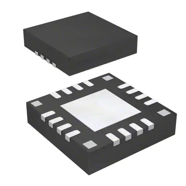
- Part No.:
- MMA6853BKWR2
- Manufacturer:
- NXP Semiconductors
- Category:
- Accelerometers
- Package:
- 16-QFN Exposed Pad
- Datasheet:
-
 MMA6853BKWR2.pdf
- Description:
- ACCELEROMETER 50G SPI 16QFN
- Quantity:
- Payment:

- Shipping:

Inventory:3,193
Please send an inquiry. Send us your inquiry, and we will respond immediately.
Product details
Overview
MMA6853BKWR2 from NXP Semiconductors (formerly Freescale) is a single-axis, ±50g, SPI-output inertial sensor designed for automotive airbag deployment control. It features 10-bit digital output, programmable arming logic, 12 selectable low-pass filter configurations (50 Hz to 1000 Hz), and AEC-Q100 Grade 1 qualification for under-hood operation.
For engineers reviewing the MMA6853BKWR2 datasheet, MMA6853BKWR2 pinout, MMA6853BKWR2 application, or MMA6853BKWR2 equivalent, this page delivers verified technical context, exact pin-level circuit roles, automotive-grade reliability data, and validated alternative part guidance - all aligned to the official MMA685x Rev 4 datasheet.
Technical Context
The MMA6853BKWR2 integrates an over-damped lateral MEMS g-cell with a sigma-delta ADC, SINC-based digital filtering, and configurable IIR low-pass filters. Its internal 8 MHz oscillator feeds a programmable clock divider to support 12 discrete cutoff frequencies across two time-constant groups (8 μs and 16 μs).
It implements dual-regulator architecture: VREG (2.5 V ±0.08 V) powers digital logic, while VREGA (2.5 V ±0.08 V) supplies analog circuitry. The ARM/PCM pin supports three arming modes - moving average, count, or unfiltered - with open-drain configuration and programmable polarity via DEVCFG_X register bits LPF[3:0] and A_CFG[2:0].
Key Specifications
| Parameter | Value and Actual Design Meaning |
|---|---|
| Full-scale range | ±50g - matches airbag crash pulse detection thresholds per ISO 26262 ASIL-B system requirements |
| Digital output resolution | 10-bit signed or unsigned - provides 9.766 LSB/g sensitivity with 0g offset at 512 (unsigned) or 0 (signed) |
| Low-pass filter options | 12 configurations (50–1000 Hz) - enables tuning for ride comfort vs. crash event discrimination |
| Supply voltage | 3.3 V or 5.0 V single supply - compatible with legacy automotive MCU power domains |
| AEC-Q100 qualification | Grade 1 (−40°C to +105°C ambient) - validated for engine compartment mounting without derating |
| Power consumption | 3.0–7.0 mA - enables continuous monitoring in always-on safety subsystems |
| Shock survivability | ±1500 g powered / ±2000 g unpowered (0.5 ms) - exceeds FMVSS 208 and ECE R94 test requirements |
Pinout & Package
Pb-free 16-pin QFN package, 6 mm × 6 mm, exposed thermal pad (Case 2086-01). Pin 17 (PAD) internally connected to VSS.
| Pin/Terminal | Circuit Role | Design Meaning |
|---|---|---|
| VREGA | Analog supply input | Must be decoupled to VSSA with ≥1 μF X7R ceramic capacitor; powers internal analog front-end and ADC reference |
| VSS / VSSA | Digital and analog ground | Separate return paths required; VSSA must be star-connected near VREGA to minimize noise coupling into g-cell signal chain |
| VREG | Digital supply input | Must be decoupled to VSS with ≥1 μF X7R capacitor; powers SPI interface, register file, and digital logic |
| VCC | Main supply input | Accepts 3.3 V or 5.0 V; powers internal regulators and bias circuits; requires 0.1 μF decoupling to VSS |
| ARM/PCM | Configurable output | Programmable as open-drain arming signal (active-high/low) or PCM output; pullup/pulldown current configurable via DEVCFG register |
| MISO/MOSI/SCLK/CS | SPI interface | Standard 4-wire SPI; CS has internal pullup, SCLK/MOSI have internal pulldowns; timing compliant with tSCLK ≥120 ns, tACCESS ≥60 ns |
| TEST/VPP | Factory programming | Must be tied to VSS in application; not user-accessible during normal operation |
Key Features
| Feature | Design Value |
|---|---|
| Programmable offset cancellation | 6.29 s averaging period with <0.25 LSB/s slew rate - enables stable zero-g calibration over temperature and lifetime drift |
| Configurable arming logic | Three modes (moving average, count, unfiltered) with programmable thresholds - eliminates need for external comparator in airbag controller |
| Self-test capability | Two-level electrostatic deflection (ΔSTLow = 10.68–18.75 g, ΔSTHI = 21.37–39.38 g) - allows in-system functional verification without mechanical stimulus |
| Dual independent power monitors | VREG and VREGA undervoltage/overvoltage detection with 20–110 mV hysteresis - ensures reliable reset behavior during battery transients |
| Robust SPI interface | 100% production-tested timing compliance (tSETUP ≥20 ns, tHOLD_IN ≥10 ns) - guarantees interoperability with automotive-grade MCUs including S32K and MPC57xx families |
Applications
| Frontal Crash Detection | Side-Impact Sensing |
|---|---|
Use Scenario: Detects rapid deceleration during head-on collisions to trigger airbag inflation within 20 ms of impact onset. IC Role / Device Role / Timing Role: Primary acceleration measurement node feeding airbag control unit (ACU); outputs 10-bit SPI data at up to 1 kHz with ≤36.5 μs datapath latency. Use Value: ±50g full-scale range and 400 Hz 4-pole LPF option match FMVSS 208 pulse shape requirements, minimizing false triggers from road noise. | Use Scenario: Mounted on B-pillar or door to detect lateral acceleration during T-bone collisions. IC Role / Device Role / Timing Role: Single-axis lateral sensing element; ARM pin configured in moving-average mode to assert deployment enable after sustained >20g threshold crossing. Use Value: Programmable arming thresholds (AWS_P/N) and 12 LPF options allow tuning for vehicle-specific side-impact dynamics without hardware change. |
| Roll-Over Detection | Pre-Crash System Input |
Use Scenario: Integrated into ESC module to monitor angular acceleration during high-speed turns or off-road maneuvers. IC Role / Device Role / Timing Role: Provides real-time X-axis acceleration data to vehicle dynamics controller; uses signed 10-bit output with zero-g offset at 0 LSB. Use Value: AEC-Q100 Grade 1 rating and −40°C to +105°C operating range ensure reliability in under-hood ESC housing environments. | Use Scenario: Feeds predictive collision algorithms by detecting early-stage braking-induced deceleration patterns. IC Role / Device Role / Timing Role: Secondary sensor in ADAS domain controller; SPI data synchronized with radar/camera timestamps via CS edge-triggered sampling. Use Value: Low-latency (<57.4 μs) and deterministic timing (tSCLK = 64/fOSC or 128/fOSC) enable precise temporal correlation with multi-sensor fusion engines. |
Equivalent & Alternatives
The following parts are listed as comparable options for similar single-axis inertial sensing applications.
| Alternative Part | Technical Difference | Application Difference | Selection Advice |
|---|---|---|---|
| MMA6851BKWR2 | ±25g full-scale range; 20.479 LSB/g sensitivity; identical pinout and SPI protocol | Lower range suits pedestrian protection systems or seatbelt pretensioner triggers where peak acceleration is <30g | Select when system-level crash modeling shows lower g-thresholds improve response time without increasing false alarm rate |
| MMA6855BKWR2 | ±120g full-scale range; 4.096 LSB/g sensitivity; same package and register map | Higher range required for heavy-duty truck airbags or rollover detection in SUVs with high center-of-gravity | Choose when testing reveals >70g events during severe crash pulses, especially in commercial vehicle platforms |
Compared with MMA6851BKWR2 and MMA6855BKWR2, the MMA6853BKWR2 offers optimal balance of resolution (9.766 LSB/g), dynamic range (±50g), and noise floor (0.5 LSB RMS) for mainstream passenger car frontal crash detection - avoiding oversensitivity of the 25g variant and undersampling risk of the 120g variant.
Availability
MMA6853BKWR2 is available at Aetrix Electronics and suitable for automotive airbag control units, electronic stability control modules, and pre-crash warning systems requiring stable component supply across extended production lifecycles.
Supply support for MMA6853BKWR2 includes scheduled delivery planning, volume procurement assistance, BOM continuity management, traceable sourcing, and lifecycle availability coordination for OEM customers, industrial embedded developers, connected-device designers, and electronics production programs.
Manufacturer
NXP Semiconductors is a global semiconductor leader focused on secure connectivity solutions for automotive, industrial, and IoT applications.
The MMA685x family was developed specifically for automotive safety-critical inertial sensing, emphasizing AEC-Q100 compliance, functional safety readiness (ISO 26262 ASIL-B capable), and robustness against mechanical shock and electrical transients.
FAQ
What is the full-scale acceleration range of the MMA6853BKWR2?
The MMA6853BKWR2 has a fixed full-scale range of ±50g, as defined in the official MMA685x datasheet Rev 4. This range is factory-trimmed and cannot be reconfigured. It delivers 9.766 LSB/g sensitivity in 10-bit unsigned mode, with zero-g output centered at 512 LSB. The MMA6853BKWR2 is distinct from other variants like MMA6851BKWR2 (±25g) and MMA6855BKWR2 (±120g), each with unique sensitivity and range calibration.
Does the MMA6853BKWR2 support both signed and unsigned SPI output formats?
Yes, the MMA6853BKWR2 supports both signed and unsigned 10-bit SPI output formats. The SD bit in the DEVCFG register (address $0B) controls this: when SD = 1, output is unsigned with 0g at 512 LSB; when SD = 0, output is signed with 0g at 0 LSB. This flexibility allows direct integration with MCU firmware expecting either format without external translation logic - a feature confirmed in Section 3.1.6.3 of the MMA685x datasheet.
How is the ARM/PCM pin configured on the MMA6853BKWR2?
The ARM/PCM pin on the MMA6853BKWR2 is configured via A_CFG[2:0] bits in the DEVCFG_X register (address $0C). Valid modes include disabled (000), PCM output (001), moving average (010/011), count (100/101), and unfiltered (110/111), with active-high or active-low polarity selectable per mode. Configuration occurs during initialization before ENDINIT is set. The MMA6853BKWR2 does not support simultaneous SPI and ARM output - the pin serves one function at a time, as documented in Table 9 of the MMA685x datasheet.
What low-pass filter options are available on the MMA6853BKWR2?
The MMA6853BKWR2 offers 12 programmable low-pass filter options: six at 8 μs time constant (cutoffs 100–1000 Hz, 4-pole) and six at 16 μs time constant (cutoffs 50–500 Hz, 4-pole or 3-pole). Selection is made via LPF[3:0] bits in DEVCFG_X register. Filter group choice affects total latency: 8 μs group yields ≤36.5 μs datapath delay, while 16 μs group yields ≤57.4 μs. All filters are implemented digitally within the ASIC and require no external components.
Is the MMA6853BKWR2 qualified to AEC-Q100 standards?
Yes, the MMA6853BKWR2 is qualified to AEC-Q100 Revision G (May 2007), specifically Grade 1 (−40°C to +105°C ambient operating temperature). This qualification covers stress tests including HTOL, TC, UHAST, and ESD (HBM ±2000 V, CDM ±750 V). The device meets automotive reliability requirements for airbag systems and is listed in Freescale's official AEC-Q100 certificate referenced in the MMA685x datasheet Section "Referenced Documents".
MMA6853BKWR2 Specifications
- Product attributes
- Attribute value
- Manufacturer:
- NXP Semiconductors
- Series:
- -
- Package/Case:
- 16-QFN Exposed Pad
- Packaging:
- Tape & Reel (TR)
- Product Status:
- Obsolete
- Type:
- Digital
- Axis:
- X, Y
- Acceleration Range:
- -
- Sensitivity (LSB/g):
- -
- Sensitivity (mV/g):
- -
- Bandwidth:
- -
- Output Type:
- SPI
- Voltage - Supply:
- 3.135V ~ 5.25V
- Features:
- -
- Operating Temperature:
- -40°C ~ 105°C
- Grade:
- Automotive
- Qualification:
- AEC-Q100
- Mounting Type:
- Surface Mount
- Supplier Device Package:
- 16-QFN-EP (6x6)
MMA6853BKWR2 FAQ
1.How can I place an order for MMA6853BKWR2 through Aetrix?
Please submit a Request for Quotation (RFQ) for MMA6853BKWR2 on Aetrix. Our sales agent will provide a competitive quotation and guide you through the order confirmation once you accept the terms.
2.Are the price and stock information for MMA6853BKWR2 reliable?
The price and inventory of MMA6853BKWR2 are updated periodically and may fluctuate due to market conditions. Stock and pricing data are typically refreshed every 24 hours. Quotation validity for MMA6853BKWR2 is usually 5 days.
3.What payment methods are accepted for MMA6853BKWR2?
We accept Wire Transfer, PayPal, Credit Card, Western Union, MoneyGram, and Escrow for MMA6853BKWR2 transactions.
Note: Certain payment methods may incur a processing fee.
4.How is shipping managed for MMA6853BKWR2?
MMA6853BKWR2 orders can be shipped via leading logistics carriers, including DHL, UPS, FedEx, TNT, or Registered Mail.
Once your MMA6853BKWR2 order is processed, you will receive an email with the shipment details and tracking number.
Note: Tracking information may take up to 24 hours to appear. Express delivery typically takes 3–5 business days.
5.How can I obtain technical support or documentation for MMA6853BKWR2?
For technical support, including MMA6853BKWR2 datasheets, pinout diagrams, or application guidance, please contact our engineering support team. They can provide detailed documentation and assistance for your MMA6853BKWR2 requirements.
6.How does Aetrix verify that MMA6853BKWR2 is sourced from the original manufacturer or authorized distributors?
All MMA6853BKWR2 products on Aetrix are procured from qualified distributors and authorized channels. Our dedicated quality assurance team conducts strict verification, including traceability checks and, if necessary, third-party testing. This ensures that MMA6853BKWR2 meets industry standards.
7.What is the process for return or replacement of MMA6853BKWR2?
All MMA6853BKWR2 units undergo pre-shipment inspection (PSI). If there is an issue with MMA6853BKWR2, returns or replacements are accepted under the following conditions:
1.Quantity discrepancies, incorrect items, or visible external defects (such as breakage or corrosion), acknowledged by Aetrix.
2.The issue is reported within 90 days of delivery.
3.The MMA6853BKWR2 part is unused and in its original packaging.
Return procedure for MMA6853BKWR2:
1.Submit a request within 90 days.
2.Obtain a Return Material Authorization (RMA) from Aetrix.
MMA6853BKWR2 Tags

-
MXC4005XC
Memsic Inc.

-
MC3419
Memsic Inc.

-
MC3479
Memsic Inc.

-
MXC6655XA
Memsic Inc.

-
MC3630
Memsic Inc.
.jpg)
-
LIS2HH12TR
STMicroelectronics

-
KX122-1037
Kionix Inc.
-
LIS2DE12TR
STMicroelectronics
-
LIS2DH12TR
STMicroelectronics

-
MC3635
Memsic Inc.
-
LIS2DS12TR
STMicroelectronics

-
LIS3DHTR
STMicroelectronics
Tech Hub

A practical engineering guide to 3.3V and 5V logic compatibility, input thresholds, resistor dividers, translator ICs, MOSFET level shifting, I2C pull-ups, timing limits and power-sequencing risks.

The 74HC595 uses push-pull logic outputs, while the TPIC6B595 uses 50 V open-drain DMOS sinks for higher-power loads. This guide compares timing, current limits, 3.3 V interfacing, load wiring, thermal…

The 74HC595 converts serial data into eight stable parallel outputs. This guide covers pin functions, shift and storage timing, OE and MR behavior, drive-current limits, cascading, voltage compatibilit…

A technical comparison of level-sensitive latches and edge-triggered flip-flops, covering timing windows, setup and hold limits, master–slave operation, time borrowing, race-through, HDL inference and…

A D latch stores one bit while Enable controls when data can pass. This reference covers gate-level operation, truth tables, transparency, setup and hold timing, LE versus OE, common ICs and practical …

An SR latch stores one bit through cross-coupled feedback. This engineering reference covers NOR and NAND implementations, truth tables, forbidden-state recovery, gated operation, switch debouncing, fa…

Latch circuits retain one bit through feedback. This technical reference covers SR and D latches, truth tables, transparency, timing limits, latch-versus-flip-flop behavior, applications and common log…

An engineering guide to LED driver operation, constant-current and constant-voltage outputs, linear and switching topologies, dimming, IC selection, calculations, replacement compatibility, and fault c…

Operational amplifier guide covering op amp basics, feedback, ideal vs real op amps, common configurations, buffer circuits, offset, bias current, gain-bandwidth, slew rate, rail-to-rail limits and sel…

Jumper cables guide covering safe connection order, red and black clamp placement, final ground connection, cable gauge, length, clamp quality, copper vs CCA cables, jump starter comparison and battery…


