
 My Inquiry
 My Account


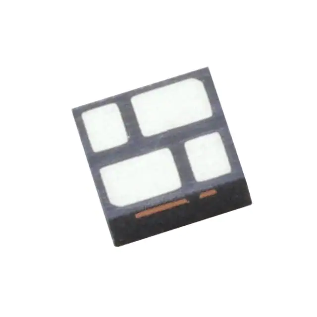
Microchip Technology MML4402-GM3/TR
- Part No.:
- MML4402-GM3/TR
- Manufacturer:
- Microchip Technology
- Category:
- RF Diodes
- Package:
- 4-SMD, No Lead
- Datasheet:
-
 MML4402-GM3/TR.pdf
- Description:
- SI LIMITER NON HERMETIC PLASTIC
- Quantity:
- Payment:

- Shipping:

Inventory:3,068
Please send an inquiry. Send us your inquiry, and we will respond immediately.
Product details
Overview
MML4402-GM3/TR from Microsemi is a RoHS-compliant fast surface-mount MRI protection diode in anti-parallel configuration, designed for passive receiver protection and detuning circuits in magnetic resonance imaging systems. It features 75 V breakdown voltage, 2.0 pF capacitance at 0 V, 1.5 Ω series resistance at 100 MHz, 20 ns turn-on time, and 40 µs conductance at 64 MHz.
For engineers reviewing the MML4402-GM3/TR datasheet, MML4402-GM3/TR pinout, MML4402-GM3/TR application, or MML4402-GM3/TR equivalent, key selection criteria include low insertion loss in both on/off states, MRI-grade non-magnetic packaging, compatibility with automatic insertion equipment, and verified performance under high-RF pulse conditions typical of 1.5T and 3T MRI scanners.
Technical Context
The MML4402-GM3/TR implements an unconnected anti-parallel diode pair in a single GM3 surface-mount package, enabling passive limiter operation without external bias or control circuitry. Its low 2.0 pF junction capacitance minimizes signal distortion in RF receive paths, while 1.5 Ω dynamic series resistance ensures minimal power dissipation during high-current RF pulses.
This device operates as a self-triggered protector: incident RF energy forward-biases the diodes during transmitter pulses, shunting excess energy away from sensitive LNAs. Its 20 ns turn-on time aligns with sinc(x) sidelobe timing to pre-empt main RF pulses, and its 40 µs conductance supports rapid recovery between pulse sequences in multi-echo MRI acquisitions.
Key Specifications
| Parameter | Value and Actual Design Meaning |
|---|---|
| Breakdown Voltage (VB) | 75 V minimum - ensures reliable clamping above MRI RF peak voltages without premature conduction during normal receive operation |
| Junction Capacitance (CT0) | 2.0 pF maximum at 0 V - preserves signal integrity and noise figure in 64–300 MHz MRI front-end receivers |
| Series Resistance (RS) | 1.5 Ω maximum at 100 MHz - limits insertion loss to <0.2 dB in 50 Ω systems during high-power limiting |
| Turn-On Time (tL) | 20 ns typical - enables protection activation before main RF pulse onset in gradient-echo and EPI sequences |
| Conductance (G) | 40 µs maximum at 64 MHz - guarantees full recovery within inter-pulse intervals of standard spin-echo protocols |
| Thermal Resistance (θP) | 20 °C/W maximum - sustains repeated 1–5 kW peak RF pulses without thermal runaway in compact coil assemblies |
Pinout & Package
Package: GM3 - low-magnetic, surface-mount, anti-parallel dual-diode configuration with 8-pin leadless ceramic structure (2.515 mm × 2.489 mm × 0.889 mm body, 1.270 mm pad length, 0.254 mm thickness). Compliant with IPC-7351B LCC-8 footprint.
| Pin/Terminal | Circuit Role | Design Meaning |
|---|---|---|
| 1, 2, 3, 4 | Anode of Diode A / Cathode of Diode B | Interconnected terminals forming one side of anti-parallel pair; tied to RF input path in limiter topology |
| 5, 6, 7, 8 | Cathode of Diode A / Anode of Diode B | Interconnected terminals forming opposite side; connected to ground or LNA input in passive protection layout |
Key Features
| Feature | Design Value |
|---|---|
| Anti-parallel diode topology | Enables bidirectional RF limiting without DC bias or control logic - critical for MRI receive chain symmetry |
| Low 2.0 pF capacitance | Maintains >40 dB return loss across 64–128 MHz band, preventing degradation of LNA noise figure |
| 20 ns turn-on response | Activates during sinc(x) sidelobes to suppress pre-pulse energy, reducing artifact generation in fast imaging |
| RoHS + 260 °C reflow compatible | Supports automated SMT assembly in high-volume MRI coil manufacturing without solder joint reliability risk |
| Non-magnetic construction | Eliminates image distortion and field homogeneity errors in 1.5T/3T MRI environments |
Applications
| Receiver Protection Limiter | Surface-Coil Detuning |
|---|---|
Use Scenario: Installed between MRI RF coil and low-noise amplifier to protect against 1–5 kW transmitter leakage pulses. IC Role / Device Role / Timing Role: Passive limiter that conducts only during high-RF events; remains transparent during receive phase. Use Value: Prevents LNA saturation and permanent damage while maintaining <0.15 dB insertion loss in receive mode. | Use Scenario: Integrated into quadrature or phased-array surface coils to disable resonant coupling during transmit. IC Role / Device Role / Timing Role: Self-triggered switch activated by loop current induced by gradient switching and RF fields. Use Value: Enables coil detuning without active drivers or timing controllers, reducing component count and EMI risk. |
| Passive Blocking Circuit | Multi-Echo Pulse Sequence Support |
Use Scenario: Used in transmit/receive (T/R) switches for small-footprint endorectal or intravascular MRI probes. IC Role / Device Role / Timing Role: Bidirectional RF shunt that blocks transmit energy from reaching receive electronics. Use Value: Achieves >35 dB isolation at 64 MHz with no DC power or control signals required. | Use Scenario: Deployed in parallel with PIN diodes (e.g., UM7201SM) in multi-echo EPI or RARE sequences. IC Role / Device Role / Timing Role: Pre-activates detuning path during sinc(x) sidelobes prior to main RF pulse. Use Value: Reduces echo train artifacts by ensuring full detuning state before first echo acquisition. |
Equivalent & Alternatives
The following parts are listed as comparable options for similar MRI protection applications.
| Alternative Part | Technical Difference | Application Difference | Selection Advice |
|---|---|---|---|
| MML4402-GM2 | Same electrical specs but GM2 package (1.27 mm × 2.03 mm); lower thermal mass and different pad layout | Preferred for space-constrained coil flex circuits where GM3's larger footprint causes routing congestion | Select MML4402-GM2 when board real estate is limited and thermal cycling is less severe than in rigid coil housings |
| MML4403-GM3 | Lower 1.0 Ω RS and 30 ns tL; higher thermal resistance (30 °C/W) | Better suited for ultra-high-power 7T MRI systems requiring lower loss but tolerating slower turn-on | Choose MML4403-GM3 only if system-level testing confirms 30 ns delay does not compromise pre-pulse suppression |
Compared with MML4402-GM3/TR, the GM2 variant offers identical protection performance in a smaller footprint but reduced thermal handling, while MML4403-GM3 trades faster limiting for lower loss-making it viable only where thermal derating and timing margins permit.
Availability
MML4402-GM3/TR is available at Aetrix Electronics and suitable for MRI coil manufacturing, medical imaging subsystem integration, and diagnostic equipment repair requiring stable component supply with full traceability and long-term lifecycle support.
Supply support for MML4402-GM3/TR includes scheduled delivery planning, volume procurement assistance, BOM continuity management, traceable sourcing, and lifecycle availability coordination for OEM customers, industrial embedded developers, connected-device designers, and electronics production programs.
Manufacturer
Microsemi Corporation (now part of Microchip Technology) is a U.S.-based semiconductor company specializing in high-reliability, radiation-tolerant, and precision timing solutions for aerospace, defense, communications, and medical markets.
The MML4400 series belongs to Microsemi's discrete protection portfolio, engineered specifically for MRI system safety and signal fidelity-addressing the unique demands of high-field RF environments, non-magnetic constraints, and passive circuit operation.
FAQ
What is the primary function of the MML4402-GM3/TR in MRI systems?
The MML4402-GM3/TR serves as a passive RF limiter and detuning enabler in MRI receiver chains. It protects low-noise amplifiers from high-power transmitter leakage by conducting only during RF pulses, while remaining electrically transparent during signal reception. Its anti-parallel configuration allows bidirectional limiting without bias, and its 2.0 pF capacitance ensures minimal impact on noise figure. The MML4402-GM3/TR is validated for use in 1.5T and 3T clinical MRI platforms.
Does the MML4402-GM3/TR require external bias or control signals to operate?
No, the MML4402-GM3/TR operates entirely passively. Its anti-parallel diode structure responds directly to incident RF voltage-no DC bias, clock, or driver circuitry is needed. During MRI transmit pulses, induced RF voltage forward-biases the diodes, shunting energy to ground. In receive mode, the device presents only 2.0 pF capacitance and negligible leakage. This self-triggered behavior is fundamental to the MML4402-GM3/TR design and eliminates failure modes associated with active control circuits.
How does the MML4402-GM3/TR differ from standard TVS diodes used in general ESD protection?
The MML4402-GM3/TR differs critically in three ways: (1) it is optimized for RF pulse limiting-not transient voltage suppression-with 20 ns turn-on aligned to MRI sinc(x) waveforms; (2) its 2.0 pF capacitance and 1.5 Ω RS preserve signal integrity in 64–128 MHz MRI bands, unlike TVS diodes with >10 pF and >5 Ω; (3) it uses non-magnetic ceramic packaging to prevent image distortion, whereas standard TVS diodes contain ferromagnetic materials. These distinctions make the MML4402-GM3/TR unsuitable as a drop-in replacement for generic TVS devices.
Can the MML4402-GM3/TR be used in 7T MRI systems?
The MML4402-GM3/TR is characterized and qualified for 1.5T and 3T MRI systems per its datasheet specifications. While its 75 V breakdown voltage and 20 ns response may appear sufficient for 7T, Microsemi does not validate or guarantee performance at 298 MHz (7T Larmor frequency) due to increased capacitive reactance and skin-effect losses. For 7T applications, MML4403-GM3-with its lower 1.0 Ω RS-is the recommended variant, and system-level testing of the MML4402-GM3/TR at 298 MHz is required before deployment.
What is the significance of the "TR" suffix in MML4402-GM3/TR?
The "TR" suffix in MML4402-GM3/TR denotes tape-and-reel packaging per Microsemi's ordering convention: it indicates the device is supplied in EIA-481-compliant carrier tape with 3,000 units per reel, optimized for automated SMT placement. This format ensures consistent orientation, static-safe handling, and compatibility with pick-and-place machines used in MRI coil assembly lines. The TR variant shares identical electrical and thermal specifications with bulk or tube-packaged versions of the MML4402-GM3/TR.
MML4402-GM3/TR Specifications
- Product attributes
- Attribute value
- Manufacturer:
- Microchip Technology
- Series:
- -
- Package/Case:
- 4-SMD, No Lead
- Packaging:
- Tape & Reel (TR)
- Product Status:
- Active
- Diode Type:
- PIN - 2 Independent
- Voltage - Peak Reverse (Max):
- 75V
- Current - Max:
- -
- Capacitance @ Vr, F:
- 2pF @ 0V, 1MHz
- Resistance @ If, F:
- 1.5Ohm @ 100mA, 100MHz
- Power Dissipation (Max):
- -
- Operating Temperature:
- -55°C ~ 150°C
- Grade:
- -
- Qualification:
- -
- Supplier Device Package:
- -
MML4402-GM3/TR FAQ
1.How can I place an order for MML4402-GM3/TR through Aetrix?
Please submit a Request for Quotation (RFQ) for MML4402-GM3/TR on Aetrix. Our sales agent will provide a competitive quotation and guide you through the order confirmation once you accept the terms.
2.Are the price and stock information for MML4402-GM3/TR reliable?
The price and inventory of MML4402-GM3/TR are updated periodically and may fluctuate due to market conditions. Stock and pricing data are typically refreshed every 24 hours. Quotation validity for MML4402-GM3/TR is usually 5 days.
3.What payment methods are accepted for MML4402-GM3/TR?
We accept Wire Transfer, PayPal, Credit Card, Western Union, MoneyGram, and Escrow for MML4402-GM3/TR transactions.
Note: Certain payment methods may incur a processing fee.
4.How is shipping managed for MML4402-GM3/TR?
MML4402-GM3/TR orders can be shipped via leading logistics carriers, including DHL, UPS, FedEx, TNT, or Registered Mail.
Once your MML4402-GM3/TR order is processed, you will receive an email with the shipment details and tracking number.
Note: Tracking information may take up to 24 hours to appear. Express delivery typically takes 3–5 business days.
5.How can I obtain technical support or documentation for MML4402-GM3/TR?
For technical support, including MML4402-GM3/TR datasheets, pinout diagrams, or application guidance, please contact our engineering support team. They can provide detailed documentation and assistance for your MML4402-GM3/TR requirements.
6.How does Aetrix verify that MML4402-GM3/TR is sourced from the original manufacturer or authorized distributors?
All MML4402-GM3/TR products on Aetrix are procured from qualified distributors and authorized channels. Our dedicated quality assurance team conducts strict verification, including traceability checks and, if necessary, third-party testing. This ensures that MML4402-GM3/TR meets industry standards.
7.What is the process for return or replacement of MML4402-GM3/TR?
All MML4402-GM3/TR units undergo pre-shipment inspection (PSI). If there is an issue with MML4402-GM3/TR, returns or replacements are accepted under the following conditions:
1.Quantity discrepancies, incorrect items, or visible external defects (such as breakage or corrosion), acknowledged by Aetrix.
2.The issue is reported within 90 days of delivery.
3.The MML4402-GM3/TR part is unused and in its original packaging.
Return procedure for MML4402-GM3/TR:
1.Submit a request within 90 days.
2.Obtain a Return Material Authorization (RMA) from Aetrix.
MML4402-GM3/TR Tags
.jpg)
-
BAP70-02,115
NXP USA Inc.
-
SMP1321-040LF
Skyworks Solutions Inc.

-
NSVR351SDSA3T1G
onsemi
-
BAT6302VH6327XTSA1
Infineon Technologies
-
SMP1307-011LF
Skyworks Solutions Inc.
-
SMP1345-040LF
Skyworks Solutions Inc.
-
BAT1503WE6327HTSA1
Infineon Technologies
-
SMS7630-005LF
Skyworks Solutions Inc.
-
SMP1322-040LF
Skyworks Solutions Inc.
-
SMS7621-040LF
Skyworks Solutions Inc.
-
SMS7621-079LF
Skyworks Solutions Inc.
-
SMS7630-040LF
Skyworks Solutions Inc.
Tech Hub

TTL and CMOS logic families differ in thresholds, loading, output drive, power and timing. This engineering guide compares 74HC and 74HCT, calculates noise margins and checks 3.3 V/5 V compatibility.

A practical engineering guide to 3.3V and 5V logic compatibility, input thresholds, resistor dividers, translator ICs, MOSFET level shifting, I2C pull-ups, timing limits and power-sequencing risks.

The 74HC595 uses push-pull logic outputs, while the TPIC6B595 uses 50 V open-drain DMOS sinks for higher-power loads. This guide compares timing, current limits, 3.3 V interfacing, load wiring, thermal…

The 74HC595 converts serial data into eight stable parallel outputs. This guide covers pin functions, shift and storage timing, OE and MR behavior, drive-current limits, cascading, voltage compatibilit…

A technical comparison of level-sensitive latches and edge-triggered flip-flops, covering timing windows, setup and hold limits, master–slave operation, time borrowing, race-through, HDL inference and…

A D latch stores one bit while Enable controls when data can pass. This reference covers gate-level operation, truth tables, transparency, setup and hold timing, LE versus OE, common ICs and practical …

An SR latch stores one bit through cross-coupled feedback. This engineering reference covers NOR and NAND implementations, truth tables, forbidden-state recovery, gated operation, switch debouncing, fa…

Latch circuits retain one bit through feedback. This technical reference covers SR and D latches, truth tables, transparency, timing limits, latch-versus-flip-flop behavior, applications and common log…

An engineering guide to LED driver operation, constant-current and constant-voltage outputs, linear and switching topologies, dimming, IC selection, calculations, replacement compatibility, and fault c…

Operational amplifier guide covering op amp basics, feedback, ideal vs real op amps, common configurations, buffer circuits, offset, bias current, gain-bandwidth, slew rate, rail-to-rail limits and sel…


