
 My Inquiry
 My Account


NXP Semiconductors PCF7991AT/1081,118
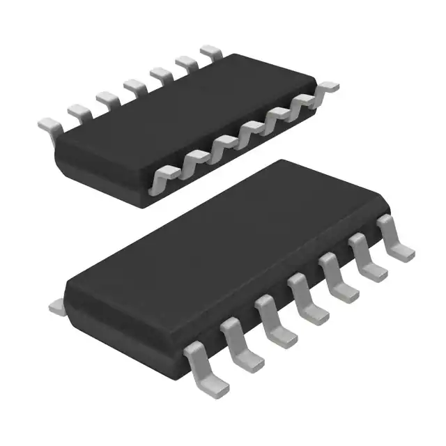
- Part No.:
- PCF7991AT/1081,118
- Manufacturer:
- NXP Semiconductors
- Category:
- RFID, RF Access, Monitoring ICs
- Package:
- 14-SOIC (0.154", 3.90mm Width)
- Datasheet:
-
 PCF7991AT/1081,118.pdf
- Description:
- IC RFID TRANSP 4-16MHZ 14SO
- Quantity:
- Payment:

- Shipping:

Inventory:1,675
Please send an inquiry. Send us your inquiry, and we will respond immediately.
Product details
Overview
PCF7991AT/1081,118 from NXP Semiconductors (formerly Philips Semiconductors) is an Advanced Basestation IC (ABIC) for vehicle immobiliser transponder communication. It delivers 200 mAp continuous-wave antenna drive, 2 mVpp receiver sensitivity, and programmable AM/PM demodulation with on-chip EMI filtering - enabling reliable read/write operation in automotive keyless entry systems.
For engineers reviewing the PCF7991AT/1081,118 datasheet, PCF7991AT/1081,118 pinout, PCF7991AT/1081,118 application, or PCF7991AT/1081,118 equivalent, key selection factors include its 14-pin SO package, 4.5–5.5 V supply range, 7 µA power-down current, ASK modulation support, and antenna failure detection capability.
Technical Context
The PCF7991AT/1081,118 integrates a programmable clock divider, serial microcontroller interface (DIN/CLK/DOUT), and synchronous AM/PM demodulator with SC filter and amplifier. Its receiver chain includes on-chip EMI filtering and fast settling after write operations.
Antenna driver output resistance is 3.5 Ω, supporting high-current CW drive up to 200 mAp; carrier frequency derivation supports both internal oscillator and external clock input, with wide-frequency adaptability via the on-chip divider.
Key Specifications
| Parameter | Value and Actual Design Meaning |
|---|---|
| Supply Voltage | 4.5–5.5 V - compatible with standard automotive 5 V rail without regulation overhead |
| Antenna Drive (CW) | 200 mAp - sufficient to energise passive LF transponders at extended distances |
| Receiver Sensitivity | 2 mVpp - enables reliable signal capture from low-coupling transponder coils |
| Power-Down Current | 7 µA @ 5.5 V - minimises standby battery drain in always-on immobiliser modules |
| Package | 14-pin SO - surface-mount footprint with validated thermal and EMI performance in automotive PCB layouts |
| Demodulation Type | Programmable AM/PM - extends operational range beyond envelope detection, critical for intelligent antenna architectures |
Pinout & Package
PCF7991AT/1081,118 is housed in a 14-pin Small Outline (SO) package with standard JEDEC MS-012AC dimensions (8.65 mm × 3.9 mm, 1.27 mm pitch). Pin functions are defined per Philips Semiconductor Application Note AN98001 and confirmed in the PCF7991 functional block diagram.
| Pin/Terminal | Circuit Role | Design Meaning |
|---|---|---|
| VDD | Positive Supply | 4.5–5.5 V main power input; decoupling required at pin for RF stability |
| VSS | Ground Reference | Digital and analog ground return; separate QGND recommended for antenna driver isolation |
| TX1 / TX2 | Antenna Driver Outputs | Differential CW drive terminals; connect to LC tank antenna circuit for 125 kHz operation |
| RX | Receiver Input | Single-ended analog input from antenna tap; feeds synchronous demodulator and SC filter |
| DIN / DOUT / CLK | Serial Interface | 3-wire SPI-compatible bus for register access and command execution with microcontroller |
| CEXT | External Capacitor | Connects to internal oscillator node; sets base carrier frequency when internal clock used |
| XTAL1 / XTAL2 | Crystal Oscillator Terminals | Supports external crystal (e.g., 1–10 MHz) for precise carrier generation |
Key Features
| Feature | Design Value |
|---|---|
| On-chip Receive EMI Filter | Reduces susceptibility to engine noise and switching transients in automotive environments without external RC networks |
| Antenna Failure Detection | Monitors open/short conditions on TX1/TX2 paths and asserts fault flag via serial interface |
| Programmable Receiver Gain & Filter | Enables dynamic adaptation to varying coil coupling, temperature, and transponder type (e.g., PCF7935 vs. PCF7961) |
| Fast Read-After-Write Settling | Minimises dead time between transponder write and response read - critical for secure challenge-response protocols |
| Low Output Resistance Driver | 3.5 Ω typical - improves power transfer efficiency into 50–100 Ω antenna impedance, reducing heat dissipation |
Applications
| Automotive Immobiliser Basestation | Intelligent Antenna Module |
|---|---|
Use Scenario: Embedded in vehicle door handle or ignition column to authenticate transponder-equipped keys during engine start. IC Role / Device Role / Timing Role: ABIC performs bidirectional 125 kHz LF communication, including carrier generation, ASK modulation, and synchronous demodulation. Use Value: 2 mVpp sensitivity and programmable gain ensure reliable read/write at >10 cm distance despite metal shielding and coil misalignment. | Use Scenario: Integrated into a compact, self-contained antenna assembly with embedded control logic and diagnostics. IC Role / Device Role / Timing Role: Provides full transponder interface plus antenna health monitoring and EMI filtering within the antenna housing itself. Use Value: On-chip antenna failure detection eliminates need for external sense resistors or op-amp comparators, reducing BOM count by ≥3 components. |
| Active Antenna System | Secure Key Fob Programming Station |
Use Scenario: Mounted near vehicle perimeter to extend detection zone for walk-away lock/unlock functionality. IC Role / Device Role / Timing Role: Drives high-Q antenna with 200 mAp CW output while maintaining stable 125 kHz carrier under load variation. Use Value: 3.5 Ω driver output resistance ensures minimal voltage drop across series inductance, preserving field strength at extended range. | Use Scenario: Used in dealership service tools to reprogram lost or damaged transponders in controlled bench environment. IC Role / Device Role / Timing Role: Executes precise timing-critical write sequences (e.g., encrypted memory page programming) via serial interface with microcontroller host. Use Value: Fast read-after-write settling (<100 µs) guarantees deterministic protocol timing, preventing transponder timeout errors during multi-step programming. |
Equivalent & Alternatives
The following parts are listed as comparable options for similar advanced basestation IC applications.
| Alternative Part | Technical Difference | Application Difference | Selection Advice |
|---|---|---|---|
| PCF7992AT/1081,118 | Same ABIC architecture but adds integrated EEPROM (128 bytes) and enhanced security registers | Required where transponder key cloning protection or firmware update storage is needed on-basestation | Select PCF7992AT/1081,118 only if on-chip nonvolatile configuration storage is mandatory |
| TDK IAM-125-01 | Module-level solution with integrated antenna, matching network, and PCF7991AT derivative ASIC; no direct pin compatibility | Used in space-constrained designs where full reference design integration reduces layout risk | Choose TDK IAM-125-01 when rapid prototyping or production volume justifies module cost premium over discrete ABIC |
Compared with PCF7991AT/1081,118, the PCF7992AT/1081,118 adds EEPROM but shares identical pinout and RF performance, whereas the TDK IAM-125-01 replaces the entire ABIC + antenna subsystem with a pre-tuned module - trading design flexibility for validation time and layout simplicity.
Availability
PCF7991AT/1081,118 is available at Aetrix Electronics and suitable for automotive immobiliser basestations, intelligent antenna modules, active antenna systems, and secure key fob programming stations requiring stable component supply across extended product lifecycles.
Supply support for PCF7991AT/1081,118 includes scheduled delivery planning, volume procurement assistance, BOM continuity management, traceable sourcing, and lifecycle availability coordination for OEM customers, industrial embedded developers, connected-device designers, and electronics production programs.
Manufacturer
NXP Semiconductors is a global semiconductor leader focused on secure connectivity solutions for automotive, industrial, and IoT applications.
The PCF7991AT/1081,118 belongs to NXP's legacy automotive security IC portfolio, specifically engineered for contactless LF transponder communication in vehicle immobilisation and access control systems.
FAQ
What is the primary function of the PCF7991AT/1081,118 in vehicle immobiliser systems?
The PCF7991AT/1081,118 serves as the Advanced Basestation IC (ABIC) responsible for generating the 125 kHz carrier, modulating data to the transponder via ASK, and demodulating the transponder's response. Its 2 mVpp sensitivity and programmable gain ensure robust communication even under challenging electromagnetic conditions encountered in automotive environments. The PCF7991AT/1081,118 integrates all core RF and interface functions required for ISO 11784/11785-compliant transponder interrogation.
Does the PCF7991AT/1081,118 support both internal and external clock sources?
Yes, the PCF7991AT/1081,118 supports dual clocking modes: an internal oscillator using the CEXT capacitor, or an external crystal connected to XTAL1/XTAL2. The on-chip programmable clock divider allows flexible carrier frequency derivation across a wide range, making the PCF7991AT/1081,118 adaptable to various transponder families and regulatory requirements without hardware changes.
How does antenna failure detection work in the PCF7991AT/1081,118?
The PCF7991AT/1081,118 monitors current flow and voltage levels on TX1 and TX2 driver outputs to detect open-circuit or short-circuit antenna faults. When triggered, it asserts a status flag accessible via the serial interface (DIN/DOUT/CLK), enabling the host microcontroller to log faults or initiate safe shutdown. This diagnostic capability is implemented entirely on-die and requires no external sensing components - a key feature of the PCF7991AT/1081,118.
What is the significance of the 3.5 Ω output resistance specification for the PCF7991AT/1081,118 antenna driver?
The 3.5 Ω typical output resistance of the PCF7991AT/1081,118's antenna driver minimises power loss in series impedance, improving efficiency when driving resonant LC tanks common in 125 kHz antennas. This low impedance enables higher effective current delivery into real-world antenna loads (typically 50–100 Ω), directly contributing to the PCF7991AT/1081,118's 200 mAp CW drive capability and extended operational range.
Can the PCF7991AT/1081,118 be used with transponders outside the Philips PCF79xx family?
Yes, the PCF7991AT/1081,118 is designed to interoperate with any ASK-modulated LF transponder, including third-party devices compliant with ISO 11784/11785. Its programmable receiver gain, filter characteristics, and demodulation parameters allow system-level tuning for different transponder sensitivities and modulation depths - a documented capability of the PCF7991AT/1081,118 confirmed in Philips Application Note AN98002.
PCF7991AT/1081,118 Specifications
- Product attributes
- Attribute value
- Manufacturer:
- NXP Semiconductors
- Series:
- -
- Package/Case:
- 14-SOIC (0.154", 3.90mm Width)
- Packaging:
- Tape & Reel (TR)
- Product Status:
- Active
- Type:
- RFID Transponder
- Frequency:
- 4MHz ~ 16MHz
- Standards:
- -
- Interface:
- -
- Voltage - Supply:
- 4.5V ~ 5.5V
- Operating Temperature:
- -40°C ~ 85°C
- Grade:
- -
- Qualification:
- -
- Mounting Type:
- Surface Mount
- Supplier Device Package:
- 14-SO
PCF7991AT/1081,118 FAQ
1.How can I place an order for PCF7991AT/1081,118 through Aetrix?
Please submit a Request for Quotation (RFQ) for PCF7991AT/1081,118 on Aetrix. Our sales agent will provide a competitive quotation and guide you through the order confirmation once you accept the terms.
2.Are the price and stock information for PCF7991AT/1081,118 reliable?
The price and inventory of PCF7991AT/1081,118 are updated periodically and may fluctuate due to market conditions. Stock and pricing data are typically refreshed every 24 hours. Quotation validity for PCF7991AT/1081,118 is usually 5 days.
3.What payment methods are accepted for PCF7991AT/1081,118?
We accept Wire Transfer, PayPal, Credit Card, Western Union, MoneyGram, and Escrow for PCF7991AT/1081,118 transactions.
Note: Certain payment methods may incur a processing fee.
4.How is shipping managed for PCF7991AT/1081,118?
PCF7991AT/1081,118 orders can be shipped via leading logistics carriers, including DHL, UPS, FedEx, TNT, or Registered Mail.
Once your PCF7991AT/1081,118 order is processed, you will receive an email with the shipment details and tracking number.
Note: Tracking information may take up to 24 hours to appear. Express delivery typically takes 3–5 business days.
5.How can I obtain technical support or documentation for PCF7991AT/1081,118?
For technical support, including PCF7991AT/1081,118 datasheets, pinout diagrams, or application guidance, please contact our engineering support team. They can provide detailed documentation and assistance for your PCF7991AT/1081,118 requirements.
6.How does Aetrix verify that PCF7991AT/1081,118 is sourced from the original manufacturer or authorized distributors?
All PCF7991AT/1081,118 products on Aetrix are procured from qualified distributors and authorized channels. Our dedicated quality assurance team conducts strict verification, including traceability checks and, if necessary, third-party testing. This ensures that PCF7991AT/1081,118 meets industry standards.
7.What is the process for return or replacement of PCF7991AT/1081,118?
All PCF7991AT/1081,118 units undergo pre-shipment inspection (PSI). If there is an issue with PCF7991AT/1081,118, returns or replacements are accepted under the following conditions:
1.Quantity discrepancies, incorrect items, or visible external defects (such as breakage or corrosion), acknowledged by Aetrix.
2.The issue is reported within 90 days of delivery.
3.The PCF7991AT/1081,118 part is unused and in its original packaging.
Return procedure for PCF7991AT/1081,118:
1.Submit a request within 90 days.
2.Obtain a Return Material Authorization (RMA) from Aetrix.
PCF7991AT/1081,118 Tags

-
SL2S2602FTBX
NXP Semiconductors

-
ST25DV04K-IER6S3
STMicroelectronics

-
ST25DV04K-IER6C3
STMicroelectronics
-
LXMSJZNCMD-217
Murata Electronics

-
NT3H2111W0FTTJ
NXP Semiconductors

-
NT3H2111W0FHKH
NXP Semiconductors

-
M24LR04E-RMC6T/2
STMicroelectronics
-
ST25DV04KC-JF6D3
STMicroelectronics

-
ST25DV64KC-IE6S3
STMicroelectronics

-
ST25DV64K-IER6T3
STMicroelectronics
-
NT3H2211W0FTTJ
NXP Semiconductors
-
NT3H2211W0FHKH
NXP Semiconductors
Tech Hub

A practical engineering guide to 3.3V and 5V logic compatibility, input thresholds, resistor dividers, translator ICs, MOSFET level shifting, I2C pull-ups, timing limits and power-sequencing risks.

The 74HC595 uses push-pull logic outputs, while the TPIC6B595 uses 50 V open-drain DMOS sinks for higher-power loads. This guide compares timing, current limits, 3.3 V interfacing, load wiring, thermal…

The 74HC595 converts serial data into eight stable parallel outputs. This guide covers pin functions, shift and storage timing, OE and MR behavior, drive-current limits, cascading, voltage compatibilit…

A technical comparison of level-sensitive latches and edge-triggered flip-flops, covering timing windows, setup and hold limits, master–slave operation, time borrowing, race-through, HDL inference and…

A D latch stores one bit while Enable controls when data can pass. This reference covers gate-level operation, truth tables, transparency, setup and hold timing, LE versus OE, common ICs and practical …

An SR latch stores one bit through cross-coupled feedback. This engineering reference covers NOR and NAND implementations, truth tables, forbidden-state recovery, gated operation, switch debouncing, fa…

Latch circuits retain one bit through feedback. This technical reference covers SR and D latches, truth tables, transparency, timing limits, latch-versus-flip-flop behavior, applications and common log…

An engineering guide to LED driver operation, constant-current and constant-voltage outputs, linear and switching topologies, dimming, IC selection, calculations, replacement compatibility, and fault c…

Operational amplifier guide covering op amp basics, feedback, ideal vs real op amps, common configurations, buffer circuits, offset, bias current, gain-bandwidth, slew rate, rail-to-rail limits and sel…

Jumper cables guide covering safe connection order, red and black clamp placement, final ground connection, cable gauge, length, clamp quality, copper vs CCA cables, jump starter comparison and battery…


