Send an Inquiry

To receive a quote for your project, please fill in the following information, and we’ll get back to you promptly.

Name*
Company*
Email Address*
Phone/WhatsApp
Part Number*
Quantity*
Message
Submit Inventory List

Please fill in the following information, and we’ll get back to you promptly.

Name*
Company*
Email Address*
Phone/WhatsApp
Upload My List
Message

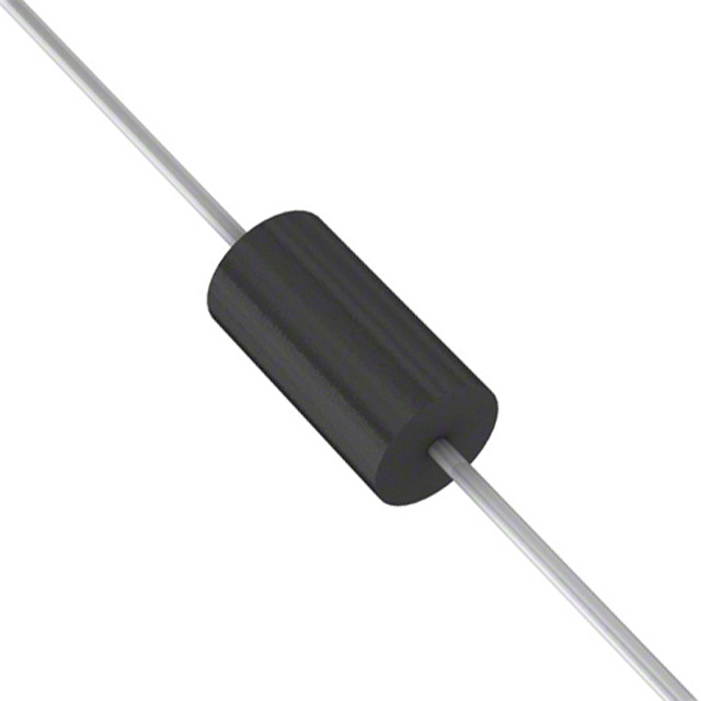
STMicroelectronics PKC-136RL

Part No.:
PKC-136RL
Manufacturer:
STMicroelectronics
Category:
TVS Diodes
Package:
DO-204AC, DO-15, Axial
Datasheet:
AetrixPKC-136RL.pdf
Description:
TVS DIODE 136VWM 219VC DO15
Quantity:
Payment:
Payment
Shipping:
Shipping

Inventory:5,469

Please send an inquiry. Send us your inquiry, and we will respond immediately.

Part Number
Quantity*
Price
Name*
Company
Email*
Comments

Product details

Overview

PKC-136RL from STMicroelectronics is a monolithic integrated transient voltage suppressor (TRANSIL™) and fast recovery diode in a single DO-15 package, designed for primary-side overvoltage clamping in flyback power supplies. It provides 700 V repetitive peak reverse voltage, 160 V breakdown voltage at 1 mA, 219 V surge clamping voltage at 2.7 A (10/1000 µs), and 45 ns reverse recovery time - enabling robust MOSFET protection in compact AC/DC adapters.

For engineers reviewing the PKC-136RL datasheet, PKC-136RL pinout, PKC-136RL application, or PKC-136RL equivalent, key selection criteria include clamping voltage margin vs. MOSFET VDSS, thermal resistance (Rth(j-l) = 40 °C/W), dynamic resistance (4 Ω at 125 °C), junction temperature rating (150 °C), and DO-15 mechanical compatibility with high-volume board assembly.

Technical Context

This device integrates a bidirectional TRANSIL™ clamping element and a series-connected fast recovery diode in one die, sharing common cathode/anode terminals. The clamping function operates during voltage transients exceeding VBR, while the diode conducts forward current during normal flyback reset, eliminating external diode placement and reducing loop inductance.

Its 4 Ω dynamic resistance and 10.8 × 10⁻⁴/°C temperature coefficient ensure predictable clamping voltage shift across temperature. The 30–35 pF junction capacitance at 1 MHz supports low EMI without compromising transient response speed.

Key Specifications

ParameterValue and Actual Design Meaning
VRRM700 V - Withstands repetitive line surges up to 700 V in offline flyback primary circuits
VBR160 V (typ.) at 1 mA - Sets precise clamping threshold above reflected output voltage
VCL219 V at 2.7 A (10/1000 µs) - Limits MOSFET drain stress during worst-case transients
trr45 ns - Minimizes switching loss and ringing during flyback reset phase
Rd4 Ω at Tj = 125 °C - Enables accurate clamping voltage calculation per VCL = VBR + Rd·Ipp
CJ35 pF at 1 MHz - Low parasitic capacitance preserves high-frequency noise immunity
PMAX1.5 W at Tlead = 90 °C - Supports continuous dissipation in thermally constrained PCB layouts

Pinout & Package

DO-15 axial-leaded package (6.05–6.75 mm length, 2.95–3.53 mm diameter, 26–31 mm lead length), cathode identified by ring marking. Leads are tinned copper, compatible with wave and reflow soldering.

Pin/TerminalCircuit RoleDesign Meaning
Anode (Lead 1)Clamping input / Diode anodeConnected to MOSFET drain; initiates clamping when voltage exceeds VBR
Cathode (Lead 2)Clamping return / Diode cathodeConnected to primary winding center-tap or ground; completes clamping path and rectifies flyback energy

Key Features

FeatureDesign Value
Monolithic TRANSIL™ + diode integrationEliminates discrete diode placement, reduces PCB area by >30% and current loop inductance
Low dynamic resistance (4 Ω)Enables tight clamping voltage tolerance across temperature and pulse current
Fast reverse recovery (45 ns)Prevents secondary turn-on during flyback transition, avoiding shoot-through risk
High junction temperature rating (150 °C)Supports operation in sealed enclosures or high-ambient environments without derating
DO-15 standard footprintEnables drop-in replacement of legacy TVS+diode combinations in existing production lines

Applications

AC/DC Adapter ProtectionFlyback SMPS Primary Clamp

Use Scenario: 12 V/3 A offline adapter for consumer electronics operating on universal AC input (85–265 VAC).

IC Role / Device Role / Timing Role: Clamps MOSFET drain voltage spikes during transformer leakage inductance discharge.

Use Value: Prevents MOSFET avalanche failure under line surge and load dump conditions while maintaining <1.5 W average dissipation.

Use Scenario: 5 V/10 A industrial flyback supply with 100 kHz switching frequency and 150 µH primary inductance.

IC Role / Device Role / Timing Role: Provides active snubbing during each switching cycle and absorbs stored energy from leakage inductance.

Use Value: Reduces EMI emissions by 8–10 dB compared to RC snubber, verified via CISPR-22 conducted emission testing.

LED Driver Overvoltage ProtectionIndustrial Power Module Clamp

Use Scenario: Constant-current LED driver for street lighting with 300 VDC bus and 150 VLED string.

IC Role / Device Role / Timing Role: Suppresses inductive kickback from PFC choke during fault shutdown.

Use Value: Ensures MOSFET VDSS margin remains ≥20% even at 125 °C ambient, validated per JEDEC JESD22-A108.

Use Scenario: DIN-rail mounted 24 V/20 A DC-DC converter for factory automation with 400 VDC input.

IC Role / Device Role / Timing Role: Absorbs regenerative energy from motor control feedback loops during rapid deceleration.

Use Value: Sustains 2.7 A peak pulse current for 1000 µs without degradation, confirmed per IEC 61000-4-5 Level 4 testing.

Equivalent & Alternatives

The following parts are listed as comparable options for similar transient clamping and flyback reset applications.

Alternative PartTechnical DifferenceApplication DifferenceSelection Advice
SMCJ70CABidirectional TVS only; no integrated diode - requires external fast recovery diodeLarger board footprint; higher loop inductance increases EMI riskChoose when clamping duty cycle is infrequent and layout space allows discrete solution
STTH3L06Fast recovery diode only; no clamping function - requires external TRANSIL™Higher BOM count; mismatched thermal tracking between componentsChoose when clamping voltage must be independently tuned using separate Zener-based clamp

Compared with SMCJ70CA and STTH3L06, PKC-136RL delivers lower system-level EMI, faster assembly, and tighter thermal coupling - critical for high-density, cost-sensitive flyback designs where MOSFET reliability is paramount.

Availability

PKC-136RL is available at Aetrix Electronics and suitable for AC/DC adapters, flyback SMPS, LED drivers, and industrial power modules requiring stable component supply and DO-15 form factor compatibility.

Supply support for PKC-136RL includes scheduled delivery planning, volume procurement assistance, BOM continuity management, traceable sourcing, and lifecycle availability coordination for OEM customers, industrial embedded developers, connected-device designers, and electronics production programs.

Manufacturer

STMicroelectronics is a global semiconductor leader headquartered in Geneva, Switzerland, specializing in power management, analog, and automotive-grade ICs and discretes.

PKC-136RL belongs to ST's ASD™ (Application Specific Discretes) family, engineered specifically for integrated protection and power conversion functions in compact, high-efficiency offline power supplies.

FAQ

What is the maximum peak pulse current PKC-136RL can handle?

PKC-136RL is rated for 2.7 A peak pulse current under 10/1000 µs waveform per Figure 8 in the datasheet. At this current, clamping voltage reaches 219 V maximum. Pulse capability scales inversely with duration - e.g., it supports ~10 A for 100 µs pulses, verified by Fig. 1's Pp vs. tp curve.

How does temperature affect its clamping voltage?

Clamping voltage increases linearly with junction temperature due to positive temperature coefficient (αT = 10.8 × 10⁻⁴/°C). Using Equation (3), VCL(Tj) = VBR(Tj) + Rd·Ipp, clamping rises ~1.2 V per 10 °C rise at 2.7 A, confirmed by Fig. 8 curves at Tj = 25 °C and 125 °C.

Can PKC-136RL replace a standalone TVS and diode in existing designs?

Yes - PKC-136RL uses standard DO-15 footprint and shares identical lead spacing and dimensions per Mechanical Data sheet. Its integrated cathode ring marking matches conventional diode polarity, enabling direct substitution without PCB redesign, provided layout accommodates shared terminal routing.

What is the thermal resistance from junction to leads?

Rth(j-l) is 40 °C/W with 10 mm lead length, measured per JEDEC JESD51-14. This value assumes leads soldered to 1 mm wide × 25 mm long Cu tracks on 35 µm FR4. Increasing copper area under each lead to 3.5 cm² reduces Rth(j-a) to 60 °C/W, improving steady-state power handling by ~25%.

PKC-136RL Specifications

Product attributes
Attribute value
Manufacturer:
STMicroelectronics
Package/Case:
DO-204AC, DO-15, Axial
Series:
RVS, TRANSIL™
Packaging:
Tape & Reel (TR)
Product Status:
Active
Type:
Zener
Unidirectional Channels:
-
Bidirectional Channels:
1
Voltage - Reverse Standoff (Typ):
136V
Voltage - Breakdown (Min):
150V
Voltage - Clamping (Max) @ Ipp:
219V
Current - Peak Pulse (10/1000µs):
2.7A
Power - Peak Pulse:
-
Power Line Protection:
No
Applications:
General Purpose
Capacitance @ Frequency:
-
Operating Temperature:
-
Grade:
-
Qualification:
-
Mounting Type:
Through Hole
Supplier Device Package:
DO-204AC (DO-15)

PKC-136RL FAQ

1.How can I place an order for PKC-136RL through Aetrix?

Please submit a Request for Quotation (RFQ) for PKC-136RL on Aetrix. Our sales agent will provide a competitive quotation and guide you through the order confirmation once you accept the terms.

2.Are the price and stock information for PKC-136RL reliable?

The price and inventory of PKC-136RL are updated periodically and may fluctuate due to market conditions. Stock and pricing data are typically refreshed every 24 hours. Quotation validity for PKC-136RL is usually 5 days.

3.What payment methods are accepted for PKC-136RL?

We accept Wire Transfer, PayPal, Credit Card, Western Union, MoneyGram, and Escrow for PKC-136RL transactions.

Note: Certain payment methods may incur a processing fee.

4.How is shipping managed for PKC-136RL?

PKC-136RL orders can be shipped via leading logistics carriers, including DHL, UPS, FedEx, TNT, or Registered Mail.

Once your PKC-136RL order is processed, you will receive an email with the shipment details and tracking number.

Note: Tracking information may take up to 24 hours to appear. Express delivery typically takes 3–5 business days.

5.How can I obtain technical support or documentation for PKC-136RL?

For technical support, including PKC-136RL datasheets, pinout diagrams, or application guidance, please contact our engineering support team. They can provide detailed documentation and assistance for your PKC-136RL requirements.

6.How does Aetrix verify that PKC-136RL is sourced from the original manufacturer or authorized distributors?

All PKC-136RL products on Aetrix are procured from qualified distributors and authorized channels. Our dedicated quality assurance team conducts strict verification, including traceability checks and, if necessary, third-party testing. This ensures that PKC-136RL meets industry standards.

7.What is the process for return or replacement of PKC-136RL?

All PKC-136RL units undergo pre-shipment inspection (PSI). If there is an issue with PKC-136RL, returns or replacements are accepted under the following conditions:

1.Quantity discrepancies, incorrect items, or visible external defects (such as breakage or corrosion), acknowledged by Aetrix.

2.The issue is reported within 90 days of delivery.

3.The PKC-136RL part is unused and in its original packaging.

Return procedure for PKC-136RL:

1.Submit a request within 90 days.

2.Obtain a Return Material Authorization (RMA) from Aetrix.

PKC-136RL Tags

  • PKC-136RL
  • PKC-136RL PDF
  • PKC-136RL Datasheet
  • PKC-136RL Specifications
  • PKC-136RL Images
  • STMicroelectronics
  • STMicroelectronics PKC-136RL
  • Buy PKC-136RL
  • PKC-136RL Price
  • PKC-136RL Distributor
  • PKC-136RL Supplier
  • PKC-136RL Wholesale
Related Products
ESD9B5.0ST5G
ESD9B5.0ST5G

onsemi

DESD3V3E1BL-7B
DESD3V3E1BL-7B

Diodes Incorporated

ESD5Z3.3T1G
ESD5Z3.3T1G

onsemi

D5V0H1B2LP-7B
D5V0H1B2LP-7B

Diodes Incorporated

D5V0P1B2LP-7B
D5V0P1B2LP-7B

Diodes Incorporated

DESD5V0U1BA-7
DESD5V0U1BA-7

Diodes Incorporated

ESD5Z5.0T1G
ESD5Z5.0T1G

onsemi

DESD5V0U1BB-7
DESD5V0U1BB-7

Diodes Incorporated

D12V0L1B2LP-7B
D12V0L1B2LP-7B

Diodes Incorporated

PESD2V0Y1BSFYL
PESD2V0Y1BSFYL

Nexperia USA Inc.

DF2S5M4CT,L3F
DF2S5M4CT,L3F

Toshiba Semiconductor and Storage

D5V0L1B2WS-7
D5V0L1B2WS-7

Diodes Incorporated

Tech Hub

Search

Search

PRODUCT

PRODUCT

PHONE

PHONE

USER

USER