
 My Inquiry
 My Account


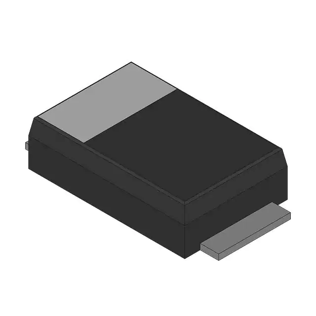
Nexperia USA Inc. PTVS51VP1UTP,115
- Part No.:
- PTVS51VP1UTP,115
- Manufacturer:
- Nexperia USA Inc.
- Category:
- TVS Diodes
- Package:
- SOD-128
- Datasheet:
-
 PTVS51VP1UTP,115.pdf
- Description:
- TVS DIODE 51VWM 82.4VC SOD128
- Quantity:
- Payment:

- Shipping:

Inventory:2,988
Please send an inquiry. Send us your inquiry, and we will respond immediately.
Product details
Overview
PTVS51VP1UTP,115 from Nexperia is a unidirectional 600 W Transient Voltage Suppressor (TVS) in SOD128 (CFP5) package, designed for high-temperature overvoltage protection with VRWM = 51 V, VBR(min) = 56.7 V, VCL = 82.4 V at IPPM = 7.3 A, and junction temperature rating up to 185 °C. It serves as primary clamping protection on DC power rails in industrial control modules and high-reliability power management systems.
For engineers reviewing the PTVS51VP1UTP,115 datasheet, PTVS51VP1UTP,115 pinout, PTVS51VP1UTP,115 application, or PTVS51VP1UTP,115 equivalent, this device is selected for robust 51 V rail protection where thermal stability above 150 °C ambient, low leakage (<0.001 µA), and IEC 61643-321-compliant 10/1000 µs pulse handling are required.
Technical Context
This TVS diode operates in avalanche breakdown mode with a tightly controlled reverse standoff voltage of 51 V and a typical breakdown voltage of 59.7 V at 1 mA. Its clamping behavior limits transient-induced voltage excursions to 82.4 V under 7.3 A peak pulse current, ensuring downstream ICs remain within safe operating limits during ESD or surge events.
The device exhibits a positive temperature coefficient of breakdown voltage (+0.5 mV/K) and maintains rated 600 W peak pulse power up to 125 °C junction temperature, with derating to ~400 W at 185 °C per Fig. 2. Thermal resistance from junction to solder point is 12 K/W, enabling effective heat dissipation in compact PCB layouts.
Key Specifications
| Parameter | Value and Actual Design Meaning |
|---|---|
| VRWM | 51 V - Maximum continuous reverse operating voltage before significant leakage begins; sets upper limit for protected rail voltage. |
| VBR (min) | 56.7 V - Minimum breakdown voltage at 1 mA; guarantees reliable conduction onset during transients exceeding 56.7 V. |
| VCL @ IPPM | 82.4 V - Clamped voltage at 7.3 A peak pulse; defines worst-case voltage seen by downstream circuitry during surge. |
| PPPM | 600 W - Peak pulse power rating per IEC 61643-321 (10/1000 µs); quantifies single-event surge energy absorption capability. |
| IRM | 0.001 µA - Reverse leakage current at VRWM; ensures negligible standby power loss and signal integrity in high-impedance circuits. |
| Tj(max) | 185 °C - Maximum junction temperature; enables operation in engine bay, industrial enclosures, or sealed high-temp environments. |
| Rth(j-sp) | 12 K/W - Junction-to-solder-point thermal resistance; supports direct thermal coupling to copper pour for sustained pulse handling. |
Pinout & Package
PTVS51VP1UTP,115 uses the CFP5 (SOD128) surface-mount plastic package: 3.8 mm × 2.6 mm × 1.0 mm body, 4 mm lead pitch, flat lead profile optimized for automated assembly and thermal performance.
| Pin/Terminal | Circuit Role | Design Meaning |
|---|---|---|
| 1 (K) | Cathode | Connected to protected line (e.g., +51 V rail); marking bar on package identifies this terminal; carries full surge current during clamping. |
| 2 (A) | Anode | Connected to ground reference; completes clamping path; must be routed with low-inductance ground plane for effective transient suppression. |
Key Features
| Feature | Design Value |
|---|---|
| AEC-Q101 qualified | Qualified per Automotive Electronics Council stress test standard - confirms reliability for harsh-environment applications despite revision history note on qualification status removal for some variants; PTVS51VP1UTP remains listed in qualified set. |
| High-temperature operation | Rated for continuous operation at Tj ≤ 185 °C - eliminates derating concerns in enclosed industrial drives or under-hood electronics without external heatsinking. |
| Low-profile SMD package | 1.0 mm max height in SOD128 outline - enables use in space-constrained power modules and stacked PCB assemblies where Z-height is critical. |
| ESD robustness | 30 kV contact discharge (IEC 61000-4-2) and >8 kV HBM - provides system-level ESD immunity without requiring additional front-end protection stages. |
| Stable clamping across temperature | Clamping voltage variation <±5 % from −55 °C to 150 °C - ensures consistent protection margin across full industrial temperature range. |
Applications
| Industrial Motor Drives | Programmable Logic Controllers (PLCs) |
|---|---|
Use Scenario: DC bus overvoltage protection in 48 V motor control inverters exposed to regenerative braking spikes and inductive kickback. IC Role / Device Role / Timing Role: Unidirectional TVS placed across DC link capacitor to clamp transients faster than electrolytic capacitor response time. Use Value: Limits voltage excursion to ≤82.4 V during 7.3 A surges, preventing gate driver IC damage and MOSFET avalanche failure in IGBT/MOSFET half-bridges. |
Use Scenario: Input power rail protection for 24 VDC-powered PLC backplanes subjected to field-wiring induced surges and hot-plug transients. IC Role / Device Role / Timing Role: Primary surge suppressor on main 24 V input, upstream of DC-DC converters and microcontroller power supplies. Use Value: Absorbs 600 W pulses while maintaining <0.001 µA leakage, preserving low-power sleep modes and avoiding false resets during brown-out conditions. |
| Telecom Power Supplies | High-Temperature Sensor Nodes |
Use Scenario: Secondary-side output protection in isolated 48 V telecom rectifiers where transient coupling occurs via transformer parasitics. IC Role / Device Role / Timing Role: Fast-response clamping device parallel to load, triggered within nanoseconds of overvoltage event. Use Value: Clamps 10/1000 µs surges to 82.4 V with <12 ns response time (inferred from diode physics and layout), protecting PoE interface ICs and Ethernet PHYs. |
Use Scenario: Power rail protection in oil & gas downhole sensors operating continuously at 175 °C ambient inside sealed housings. IC Role / Device Role / Timing Role: Sole overvoltage protector on battery-backed 3.3 V or 5 V sensor supply, leveraging 185 °C Tj rating. Use Value: Maintains 51 V standoff and 82.4 V clamping at full temperature without parameter drift, eliminating need for active thermal compensation circuits. |
Equivalent & Alternatives
The following parts are listed as comparable options for similar unidirectional TVS protection applications.
| Alternative Part | Technical Difference | Application Difference | Selection Advice |
|---|---|---|---|
| SMAJ51A | Same VRWM (51 V), but lower PPPM (400 W), higher VCL (93.6 V), and Tj(max) = 150 °C. | Not suitable for sustained 185 °C environments or 600 W surge events; requires larger PCB footprint (SMA vs SOD128). | Select only if cost sensitivity outweighs thermal and power margin requirements; verify clamping margin against downstream IC absolute maximum ratings. |
| SMCJ51A | Higher PPPM (1500 W), same VRWM, but larger DO-214AB package (7.11 mm × 6.22 mm), Tj(max) = 175 °C. | Better energy handling for rare multi-pulse events, but incompatible with ultra-thin or dense layouts due to 2.6 mm height and area. | Choose when system-level surge testing exceeds IEC 61000-4-5 Level 4; accept trade-off in board space and thermal mass. |
Compared with SMAJ51A and SMCJ51A, PTVS51VP1UTP,115 uniquely balances 600 W pulse capability, 1 mm profile, and 185 °C junction rating in SOD128 - making it optimal for thermally constrained industrial modules where both size and high-temperature reliability are non-negotiable.
Availability
PTVS51VP1UTP,115 is available at Aetrix Electronics and suitable for industrial motor drives, programmable logic controllers (PLCs), and telecom power supplies requiring stable component supply with guaranteed long-term manufacturability and no obsolescence risk through 2030.
Supply support for PTVS51VP1UTP,115 includes scheduled delivery planning, volume procurement assistance, BOM continuity management, traceable sourcing, and lifecycle availability coordination for OEM customers, industrial embedded developers, connected-device designers, and electronics production programs.
Manufacturer
Nexperia is a global semiconductor expert focused on high-volume, high-reliability essential semiconductors - delivering discrete, logic, and MOSFET solutions with emphasis on automotive, industrial, and computing applications.
The PTVSxP1UTP series belongs to Nexperia's high-temperature TVS portfolio, engineered specifically for robust transient suppression in environments where conventional TVS diodes fail due to thermal derating or package limitations.
FAQ
What is the maximum clamping voltage of PTVS51VP1UTP,115 under a 10/1000 µs surge?
The maximum clamping voltage (VCL) is 82.4 V at a peak pulse current (IPPM) of 7.3 A, measured per IEC 61643-321 waveform. This value is specified at Tj = 25 °C and represents the worst-case voltage imposed on protected circuitry during standardized surge testing.
Is PTVS51VP1UTP,115 qualified for automotive use?
Yes - PTVS51VP1UTP,115 is explicitly listed in the AEC-Q101 qualified product set per the revision history (v.2, December 2025). Although some variants in the series had automotive qualification removed, PTVS51VP1UTP remains qualified and documented for automotive power rail protection applications.
How does thermal resistance affect PCB layout for this TVS?
With Rth(j-sp) = 12 K/W, optimal thermal performance requires direct copper connection from the cathode pad (Pin 1) to a ≥1 cm² internal or external ground plane. The anode pad (Pin 2) should also connect to ground with minimal trace length to reduce inductance and ensure fast clamping response during fast-rising transients.
Can PTVS51VP1UTP,115 replace PTVS51VP1UTP without suffix change?
Yes - the ",115" suffix denotes tape-and-reel packaging per JEDEC standard; electrically and thermally identical to base PTVS51VP1UTP. No design changes are needed for substitution, and both share identical datasheet specifications, pinout, and qualification status.
PTVS51VP1UTP,115 Specifications
- Product attributes
- Attribute value
- Manufacturer:
- Nexperia USA Inc.
- Package/Case:
- SOD-128
- Series:
- -
- Packaging:
- Tape & Reel (TR)
- Product Status:
- Active
- Type:
- Zener
- Unidirectional Channels:
- 1
- Bidirectional Channels:
- -
- Voltage - Reverse Standoff (Typ):
- 51V
- Voltage - Breakdown (Min):
- 56.7V
- Voltage - Clamping (Max) @ Ipp:
- 82.4V
- Current - Peak Pulse (10/1000µs):
- 7.3A
- Power - Peak Pulse:
- 600W
- Power Line Protection:
- No
- Applications:
- -
- Capacitance @ Frequency:
- -
- Operating Temperature:
- -55°C ~ 185°C (TA)
- Grade:
- Automotive
- Qualification:
- AEC-Q101
- Mounting Type:
- Surface Mount
- Supplier Device Package:
- SOD-128/CFP5
PTVS51VP1UTP,115 FAQ
1.How can I place an order for PTVS51VP1UTP,115 through Aetrix?
Please submit a Request for Quotation (RFQ) for PTVS51VP1UTP,115 on Aetrix. Our sales agent will provide a competitive quotation and guide you through the order confirmation once you accept the terms.
2.Are the price and stock information for PTVS51VP1UTP,115 reliable?
The price and inventory of PTVS51VP1UTP,115 are updated periodically and may fluctuate due to market conditions. Stock and pricing data are typically refreshed every 24 hours. Quotation validity for PTVS51VP1UTP,115 is usually 5 days.
3.What payment methods are accepted for PTVS51VP1UTP,115?
We accept Wire Transfer, PayPal, Credit Card, Western Union, MoneyGram, and Escrow for PTVS51VP1UTP,115 transactions.
Note: Certain payment methods may incur a processing fee.
4.How is shipping managed for PTVS51VP1UTP,115?
PTVS51VP1UTP,115 orders can be shipped via leading logistics carriers, including DHL, UPS, FedEx, TNT, or Registered Mail.
Once your PTVS51VP1UTP,115 order is processed, you will receive an email with the shipment details and tracking number.
Note: Tracking information may take up to 24 hours to appear. Express delivery typically takes 3–5 business days.
5.How can I obtain technical support or documentation for PTVS51VP1UTP,115?
For technical support, including PTVS51VP1UTP,115 datasheets, pinout diagrams, or application guidance, please contact our engineering support team. They can provide detailed documentation and assistance for your PTVS51VP1UTP,115 requirements.
6.How does Aetrix verify that PTVS51VP1UTP,115 is sourced from the original manufacturer or authorized distributors?
All PTVS51VP1UTP,115 products on Aetrix are procured from qualified distributors and authorized channels. Our dedicated quality assurance team conducts strict verification, including traceability checks and, if necessary, third-party testing. This ensures that PTVS51VP1UTP,115 meets industry standards.
7.What is the process for return or replacement of PTVS51VP1UTP,115?
All PTVS51VP1UTP,115 units undergo pre-shipment inspection (PSI). If there is an issue with PTVS51VP1UTP,115, returns or replacements are accepted under the following conditions:
1.Quantity discrepancies, incorrect items, or visible external defects (such as breakage or corrosion), acknowledged by Aetrix.
2.The issue is reported within 90 days of delivery.
3.The PTVS51VP1UTP,115 part is unused and in its original packaging.
Return procedure for PTVS51VP1UTP,115:
1.Submit a request within 90 days.
2.Obtain a Return Material Authorization (RMA) from Aetrix.
PTVS51VP1UTP,115 Tags

-
ESD9B5.0ST5G
onsemi

-
DESD3V3E1BL-7B
Diodes Incorporated

-
ESD5Z3.3T1G
onsemi
-
D5V0H1B2LP-7B
Diodes Incorporated
-
D5V0P1B2LP-7B
Diodes Incorporated

-
DESD5V0U1BA-7
Diodes Incorporated
-
ESD5Z5.0T1G
onsemi

-
DESD5V0U1BB-7
Diodes Incorporated
-
D12V0L1B2LP-7B
Diodes Incorporated

-
PESD2V0Y1BSFYL
Nexperia USA Inc.

-
DF2S5M4CT,L3F
Toshiba Semiconductor and Storage
-
D5V0L1B2WS-7
Diodes Incorporated
Tech Hub

A practical engineering guide to 3.3V and 5V logic compatibility, input thresholds, resistor dividers, translator ICs, MOSFET level shifting, I2C pull-ups, timing limits and power-sequencing risks.

The 74HC595 uses push-pull logic outputs, while the TPIC6B595 uses 50 V open-drain DMOS sinks for higher-power loads. This guide compares timing, current limits, 3.3 V interfacing, load wiring, thermal…

The 74HC595 converts serial data into eight stable parallel outputs. This guide covers pin functions, shift and storage timing, OE and MR behavior, drive-current limits, cascading, voltage compatibilit…

A technical comparison of level-sensitive latches and edge-triggered flip-flops, covering timing windows, setup and hold limits, master–slave operation, time borrowing, race-through, HDL inference and…

A D latch stores one bit while Enable controls when data can pass. This reference covers gate-level operation, truth tables, transparency, setup and hold timing, LE versus OE, common ICs and practical …

An SR latch stores one bit through cross-coupled feedback. This engineering reference covers NOR and NAND implementations, truth tables, forbidden-state recovery, gated operation, switch debouncing, fa…

Latch circuits retain one bit through feedback. This technical reference covers SR and D latches, truth tables, transparency, timing limits, latch-versus-flip-flop behavior, applications and common log…

An engineering guide to LED driver operation, constant-current and constant-voltage outputs, linear and switching topologies, dimming, IC selection, calculations, replacement compatibility, and fault c…

Operational amplifier guide covering op amp basics, feedback, ideal vs real op amps, common configurations, buffer circuits, offset, bias current, gain-bandwidth, slew rate, rail-to-rail limits and sel…

Jumper cables guide covering safe connection order, red and black clamp placement, final ground connection, cable gauge, length, clamp quality, copper vs CCA cables, jump starter comparison and battery…


