
 My Inquiry
 My Account


Texas Instruments TMS37157IRSARG4
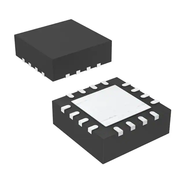
- Part No.:
- TMS37157IRSARG4
- Manufacturer:
- Texas Instruments
- Category:
- RFID, RF Access, Monitoring ICs
- Package:
- 16-VQFN Exposed Pad
- Datasheet:
-
 TMS37157IRSARG4.pdf
- Description:
- IC RFID TRANSP 134.2KHZ 16QFN
- Quantity:
- Payment:

- Shipping:

Inventory:3,680
Please send an inquiry. Send us your inquiry, and we will respond immediately.
Product details
Overview
TMS37157IRSARG4 from Texas Instruments is a passive low-frequency transponder interface IC with integrated 121-byte EEPROM, 134.2 kHz HDX communication, ultra-low-power operation (60 nA in power-down mode), and SPI/microcontroller co-processor capability for batteryless sensor and configuration memory applications.
For engineers reviewing the TMS37157IRSARG4 datasheet, TMS37157IRSARG4 pinout, TMS37157IRSARG4 application, or TMS37157IRSARG4 equivalent, this page delivers verified electrical parameters, LF transponder timing constraints, SPI interface behavior, push-button wake-up logic, and EEPROM lock/protect architecture - all confirmed from TI's SWRS083A datasheet and official ordering documentation.
Technical Context
The TMS37157IRSARG4 implements a DST-compatible 134.2 kHz half-duplex transponder front end with on-chip resonance trimming (0–85.9 pF total capacitance), RF limiter (10.5–14 V), and clock regeneration from incoming LF field. It supports PPM-encoded downlink (ASk) and FSK uplink (8 kbit/s max) without battery support.
Its control unit manages dual power domains: RF-field-derived VCL (5.75–6.5 V activation threshold) powers transponder functions and charge capacitor CL (220 nF typical), while VBAT (2–3.6 V) supplies SPI and microcontroller interface. The NPOR open-drain reset output and BUSY handshaking signal coordinate deterministic SPI access during transponder activity.
Key Specifications
| Parameter | Value and Actual Design Meaning |
|---|---|
| Operating Frequency | 134.2 kHz ±0.04 kHz - precisely trimmed via internal 7-bit capacitor array for stable HF coupling in metal/noisy environments. |
| Supply Voltage Range | 2.0 V to 3.6 V - supports direct connection to coin-cell or energy-harvested sources; VBATI output provides regulated μC supply. |
| Power Consumption | 60 nA (power-down), 150 μA (active) - enables multi-year batteryless operation in data loggers and remote sensors. |
| EEPROM Capacity | 126 bytes total: 121 free user bytes + 4-byte serial number + 1-byte selective address - pages 8–15 and 40–55 are lockable/protectable. |
| Data Rate | Up to 8 kbit/s LF uplink - achieved via frequency-shift keying (FSK) enabling fast sensor readout over short-range LF link. |
| Interface | 3-wire SPI (CLK/SOMI/SIMO) + test interface (TCLK/TDAT/TEN) - enables secure in-system programming and antenna tuning without external tools. |
| Activation Threshold | VCL ≥5.75 V - ensures reliable wake-up only when sufficient RF field strength (≥0.64 mA short-circuit current at Qop ≥30) is present. |
Pinout & Package
Package: 4 mm × 4 mm, 0.6 mm pitch, 16-pin VQFN (RSA). Thermal pad exposed on underside for enhanced power dissipation in continuous transponder operation.
| Pin/Terminal | Circuit Role | Design Meaning |
|---|---|---|
| RF1 | Antenna input | Single-ended LF coil connection; integrates RF limiter and rectifier for VCL generation. |
| TCLK, TDAT, TEN | Test interface I/O | Used for factory trimming of resonance capacitor array; requires 5 V VCL supply and precise timing (134 kHz clock). |
| NPOR | Active-low reset output | Open-drain signal to reset connected microcontroller; asserted during power-on and transponder initialization. |
| PUSH | Push-button detector input | Ultra-low-power wake-up trigger - pulls high to activate control unit and enable VBATI supply to μC. |
| BUSY | Activity status indicator | High during transponder response, SPI transfer, or initialization - used for hardware handshaking with μC. |
| CLKA/M | Resonance-derived clock output | Provides FRES or FRES/4 clock to μC; enabled via SPI command - eliminates need for separate crystal oscillator. |
| VBATI | μC supply output | Regulated voltage derived from VBAT; powers external microcontroller only when transponder is active or PUSH is asserted. |
| VCL | Charge capacitor node | Stores harvested RF energy; powers analog front end and transponder logic - must reach ≥5.75 V for activation. |
Key Features
| Feature | Design Value |
|---|---|
| Batteryless EEPROM access | Full 121-byte user memory readable/writable over LF interface without VBAT - enables configuration storage in sealed, maintenance-free devices. |
| Selective addressing mode | Page 1 holds 8-bit password; non-0xFF value enables anti-collision and secure page-level locking/protection - prevents unauthorized reprogramming. |
| Irreversible memory protection | Pages 8–15 and 40–55 support irreversible lock bits (write-disable) and protection bits (SPI-only write) - ensures firmware/data integrity in field-deployed units. |
| Integrated resonance trimming | Seven programmable capacitors (0.6–37.6 pF each) yield 128-step adjustment - compensates for ±2.8% inductor tolerance and PCB parasitics. |
| Push-button wake-up with power management | Dedicated PUSH input triggers VBATI enable and μC reset via NPOR - reduces system standby current to <100 nA including μC. |
Applications
| Wireless Sensor Node | Batteryless Smart Meter |
|---|---|
|
Use Scenario: Temperature/humidity sensor powered solely by LF field during reader interrogation; logs data to TMS37157IRSARG4 EEPROM between reads. IC Role / Device Role / Timing Role: Passive transponder interface and nonvolatile memory manager - handles PPM downlink decoding, FSK uplink transmission, and SPI-based sensor data staging. Use Value: Eliminates battery replacement in inaccessible locations; 10-year data retention and 200,000 program/erase cycles ensure long-term reliability. |
Use Scenario: Utility meter stores calibration coefficients, tamper logs, and billing history in TMS37157IRSARG4 EEPROM; accessed remotely via handheld LF reader. IC Role / Device Role / Timing Role: Secure configuration memory and transponder controller - uses selective addressing and irreversible page locks to prevent unauthorized parameter modification. Use Value: Meets IEC 62056-62 security requirements; 32-bit unique serial number enables device-level traceability across fleet deployments. |
| Remote Control Key Fob | Industrial Asset Tag |
|
Use Scenario: Key fob with push-button wake-up transmits encrypted ID and button state via TMS37157IRSARG4 to base station; no battery required. IC Role / Device Role / Timing Role: Low-power transponder and event-triggered data transmitter - leverages PUSH input to initiate VBATI-powered μC and transmit payload within 12 ms response time. Use Value: Extends fob lifetime indefinitely; 60 nA sleep current prevents self-discharge; EOB detection synchronizes transmission to reader field-off periods. |
Use Scenario: Metal-mounted asset tag stores maintenance history, firmware version, and location ID; read by portable LF scanner in harsh industrial environments. IC Role / Device Role / Timing Role: Ruggedized LF transponder with noise-immune HDX interface - integrated RF limiter (14 V max) and Q-factor optimization (>30) maintain link integrity near motors and welders. Use Value: Operates reliably at −40°C to +85°C; 134.2 kHz band avoids interference from 2.4 GHz wireless systems; VQFN package withstands vibration and thermal cycling. |
Equivalent & Alternatives
The following parts are listed as comparable options for similar passive LF transponder interface applications.
| Alternative Part | Technical Difference | Application Difference | Selection Advice |
|---|---|---|---|
| ATA5577M1600-TAQY | 125 kHz operation; 256-bit read-only memory; no user EEPROM or SPI interface. | Limited to fixed-ID RFID tags; cannot store dynamic sensor data or support μC co-processing. | Choose for simple identification-only use cases where cost and minimal external components are critical. |
| SL2S2201P | 13.56 MHz HF interface; ISO 15693 compliant; 2 KB EEPROM; no LF harvesting or push-button wake-up. | Requires powered reader field; incompatible with batteryless LF energy harvesting architectures. | Choose when integrating with existing HF infrastructure or requiring higher data throughput and larger memory. |
Compared with ATA5577M1600-TAQY and SL2S2201P, the TMS37157IRSARG4 uniquely combines 134.2 kHz batteryless operation, 121-byte programmable EEPROM, SPI co-processor interface, and push-button wake-up - making it the only option for autonomous, field-updatable, ultra-low-power sensor nodes requiring LF robustness.
Availability
TMS37157IRSARG4 is available at Aetrix Electronics and suitable for wireless sensor nodes, batteryless smart meters, remote control key fobs, and industrial asset tags requiring stable component supply across extended temperature ranges and long product lifecycles.
Supply support for TMS37157IRSARG4 includes scheduled delivery planning, volume procurement assistance, BOM continuity management, traceable sourcing, and lifecycle availability coordination for OEM customers, industrial embedded developers, connected-device designers, and electronics production programs.
Manufacturer
Texas Instruments is a global semiconductor company specializing in analog, embedded processing, and connectivity technologies, with leadership in low-power design and industrial-grade reliability.
The TMS37157IRSARG4 belongs to TI's passive RFID and sensor interface product line, engineered specifically for batteryless, energy-harvested systems requiring secure, field-updatable memory and robust 134.2 kHz communication in electrically noisy environments.
FAQ
What is the minimum RF field strength required to activate the TMS37157IRSARG4?
The TMS37157IRSARG4 requires a minimum short-circuit current of 0.64 mA at the transponder coil position when the operating quality factor Qop ≥30. This corresponds to an activation voltage of ≥5.75 V at the VCL pin, measured just before transponder response begins. Field strength must sustain this level for ≥20 ms charge time per TI SWRS083A specifications. The TMS37157IRSARG4 will not respond below this threshold to prevent false triggers in marginal RF conditions.
Can the TMS37157IRSARG4 operate without any battery connected?
Yes, the TMS37157IRSARG4 supports full batteryless operation: its EEPROM is readable and writable over the 134.2 kHz LF interface without VBAT, and the analog front end is powered entirely from harvested RF energy stored on the VCL capacitor. Battery connection (VBAT) is optional and only needed to power the SPI interface or enable VBATI-supplied microcontrollers during active sessions.
How does the selective addressing feature work in the TMS37157IRSARG4?
Selective addressing in the TMS37157IRSARG4 is enabled by writing any value other than 0xFF to byte 0 of Page 1. Once set, all subsequent Program, Lock, Protect, and Selective Read commands require inclusion of this 8-bit password in the command frame. The TMS37157IRSARG4 compares the received address against the stored value; mismatch halts command execution. This prevents unauthorized access in multi-tag environments and supports anti-collision protocols.
What is the purpose of the CLKAM pin on the TMS37157IRSARG4?
CLKAM (Clock from Antenna Module) outputs a clean, resonance-derived clock signal - either FRES (134.2 kHz) or FRES/4 (33.55 kHz) - to the connected microcontroller. Enabled via SPI command, this eliminates the need for a separate crystal oscillator or RC timing circuit. The TMS37157IRSARG4 generates CLKAM directly from the antenna LC tank, ensuring precise synchronization between reader and transponder timing without additional components.
Is the EEPROM memory in the TMS37157IRSARG4 lockable at the page level?
Yes, the TMS37157IRSARG4 supports irreversible page-level locking for all 126 bytes of transponder memory. Each page (e.g., Page 1, Page 2, Pages 8–15, Pages 40–55) has a dedicated lock bit that, once set via Lock Page command, permanently disables further writes to that page. Locked pages remain readable via LF or SPI. This ensures configuration constants, calibration data, or cryptographic keys remain tamper-proof throughout the device's operational life.
TMS37157IRSARG4 Specifications
- Product attributes
- Attribute value
- Manufacturer:
- Texas Instruments
- Series:
- -
- Package/Case:
- 16-VQFN Exposed Pad
- Packaging:
- Tape & Reel (TR)
- Product Status:
- Active
- Type:
- RFID Transponder
- Frequency:
- 134.2kHz
- Standards:
- -
- Interface:
- SPI
- Voltage - Supply:
- 2V ~ 3.6V
- Operating Temperature:
- -40°C ~ 85°C
- Grade:
- -
- Qualification:
- -
- Mounting Type:
- Surface Mount
- Supplier Device Package:
- 16-QFN (4x4)
TMS37157IRSARG4 FAQ
1.How can I place an order for TMS37157IRSARG4 through Aetrix?
Please submit a Request for Quotation (RFQ) for TMS37157IRSARG4 on Aetrix. Our sales agent will provide a competitive quotation and guide you through the order confirmation once you accept the terms.
2.Are the price and stock information for TMS37157IRSARG4 reliable?
The price and inventory of TMS37157IRSARG4 are updated periodically and may fluctuate due to market conditions. Stock and pricing data are typically refreshed every 24 hours. Quotation validity for TMS37157IRSARG4 is usually 5 days.
3.What payment methods are accepted for TMS37157IRSARG4?
We accept Wire Transfer, PayPal, Credit Card, Western Union, MoneyGram, and Escrow for TMS37157IRSARG4 transactions.
Note: Certain payment methods may incur a processing fee.
4.How is shipping managed for TMS37157IRSARG4?
TMS37157IRSARG4 orders can be shipped via leading logistics carriers, including DHL, UPS, FedEx, TNT, or Registered Mail.
Once your TMS37157IRSARG4 order is processed, you will receive an email with the shipment details and tracking number.
Note: Tracking information may take up to 24 hours to appear. Express delivery typically takes 3–5 business days.
5.How can I obtain technical support or documentation for TMS37157IRSARG4?
For technical support, including TMS37157IRSARG4 datasheets, pinout diagrams, or application guidance, please contact our engineering support team. They can provide detailed documentation and assistance for your TMS37157IRSARG4 requirements.
6.How does Aetrix verify that TMS37157IRSARG4 is sourced from the original manufacturer or authorized distributors?
All TMS37157IRSARG4 products on Aetrix are procured from qualified distributors and authorized channels. Our dedicated quality assurance team conducts strict verification, including traceability checks and, if necessary, third-party testing. This ensures that TMS37157IRSARG4 meets industry standards.
7.What is the process for return or replacement of TMS37157IRSARG4?
All TMS37157IRSARG4 units undergo pre-shipment inspection (PSI). If there is an issue with TMS37157IRSARG4, returns or replacements are accepted under the following conditions:
1.Quantity discrepancies, incorrect items, or visible external defects (such as breakage or corrosion), acknowledged by Aetrix.
2.The issue is reported within 90 days of delivery.
3.The TMS37157IRSARG4 part is unused and in its original packaging.
Return procedure for TMS37157IRSARG4:
1.Submit a request within 90 days.
2.Obtain a Return Material Authorization (RMA) from Aetrix.
TMS37157IRSARG4 Tags

-
SL2S2602FTBX
NXP Semiconductors

-
ST25DV04K-IER6S3
STMicroelectronics

-
ST25DV04K-IER6C3
STMicroelectronics
-
LXMSJZNCMD-217
Murata Electronics

-
NT3H2111W0FTTJ
NXP Semiconductors

-
NT3H2111W0FHKH
NXP Semiconductors

-
M24LR04E-RMC6T/2
STMicroelectronics
-
ST25DV04KC-JF6D3
STMicroelectronics

-
ST25DV64KC-IE6S3
STMicroelectronics

-
ST25DV64K-IER6T3
STMicroelectronics
-
NT3H2211W0FTTJ
NXP Semiconductors
-
NT3H2211W0FHKH
NXP Semiconductors
Tech Hub

A practical engineering guide to 3.3V and 5V logic compatibility, input thresholds, resistor dividers, translator ICs, MOSFET level shifting, I2C pull-ups, timing limits and power-sequencing risks.

The 74HC595 uses push-pull logic outputs, while the TPIC6B595 uses 50 V open-drain DMOS sinks for higher-power loads. This guide compares timing, current limits, 3.3 V interfacing, load wiring, thermal…

The 74HC595 converts serial data into eight stable parallel outputs. This guide covers pin functions, shift and storage timing, OE and MR behavior, drive-current limits, cascading, voltage compatibilit…

A technical comparison of level-sensitive latches and edge-triggered flip-flops, covering timing windows, setup and hold limits, master–slave operation, time borrowing, race-through, HDL inference and…

A D latch stores one bit while Enable controls when data can pass. This reference covers gate-level operation, truth tables, transparency, setup and hold timing, LE versus OE, common ICs and practical …

An SR latch stores one bit through cross-coupled feedback. This engineering reference covers NOR and NAND implementations, truth tables, forbidden-state recovery, gated operation, switch debouncing, fa…

Latch circuits retain one bit through feedback. This technical reference covers SR and D latches, truth tables, transparency, timing limits, latch-versus-flip-flop behavior, applications and common log…

An engineering guide to LED driver operation, constant-current and constant-voltage outputs, linear and switching topologies, dimming, IC selection, calculations, replacement compatibility, and fault c…

Operational amplifier guide covering op amp basics, feedback, ideal vs real op amps, common configurations, buffer circuits, offset, bias current, gain-bandwidth, slew rate, rail-to-rail limits and sel…

Jumper cables guide covering safe connection order, red and black clamp placement, final ground connection, cable gauge, length, clamp quality, copper vs CCA cables, jump starter comparison and battery…


