
 My Inquiry
 My Account


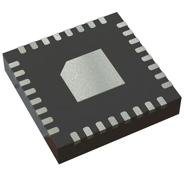
Texas Instruments TRF7963ARHBT
- Part No.:
- TRF7963ARHBT
- Manufacturer:
- Texas Instruments
- Category:
- RFID, RF Access, Monitoring ICs
- Package:
- 32-VFQFN Exposed Pad
- Datasheet:
-
 TRF7963ARHBT.pdf
- Description:
- IC RFID READER 13.56MHZ 32VQFN
- Quantity:
- Payment:

- Shipping:

Inventory:6,990
Please send an inquiry. Send us your inquiry, and we will respond immediately.
Product details
Overview
TRF7963ARHBT from Texas Instruments is a fully integrated 13.56-MHz RFID reader/writer IC supporting ISO/IEC 14443A, ISO/IEC 14443B, NFC Forum Types 1–4, and FeliCa protocols. It delivers +20 dBm or +23 dBm RF output power, operates from 2.7 V to 5.5 V input supply, and features dual-receiver architecture with RSSI for robust tag reading in noisy environments-used in secure access control systems and digital door locks.
For engineers reviewing the TRF7963ARHBT datasheet, TRF7963ARHBT pinout, TRF7963ARHBT application, or TRF7963ARHBT equivalent, key selection considerations include its programmable I/O voltage (1.8–5.5 V), SPI/parallel interface flexibility, ultra-low-power modes (<0.5 µA in Power Down 1), integrated 3.4-V digital regulator (VDD_X), and 32-pin QFN package with thermal pad grounding.
Technical Context
The TRF7963ARHBT integrates analog front-end (AFE) and protocol framing logic for 13.56-MHz RFID systems. Its dual-input receiver architecture enables simultaneous signal capture from RX_IN1 and RX_IN2, with automatic gain control and RSSI reporting to eliminate read holes and suppress ambient in-band noise.
It supports data rates up to 848 kbps across all ISO/IEC 14443 variants and NFC Forum tag types via on-chip encoders/decoders. Direct Mode 0 provides full AFE control and raw subcarrier access, while Direct Mode 2 enables hardware-accelerated NFC tag type 2/3/4 handling without MCU intervention.
Key Specifications
| Parameter | Value and Actual Design Meaning |
|---|---|
| Operating Frequency | 13.56 MHz carrier frequency, crystal-controlled with external 13.56-MHz oscillator or crystal. |
| RF Output Power | +20 dBm (100 mW) or +23 dBm (200 mW) into 50 Ω at 5 V supply-selectable for range vs. EMI trade-offs. |
| Supply Voltage Range | 2.7 V to 5.5 V on VIN pin-supports battery-powered and USB-supplied portable readers. |
| I/O Logic Level Range | 1.8 V to 5.5 V on VDD_I/O-enables direct interfacing with 1.8-V, 3.3-V, or 5-V MCUs without level shifters. |
| Power Consumption | <0.5 µA in Power Down Mode 1-enables multi-year battery life in low-duty-cycle access terminals. |
| Data Interface | SPI or 8-bit parallel bus-SPI supports up to 10 MHz clock (≤30 pF load); parallel mode uses I/O_0–I/O_7 bidirectional pins. |
| Regulated Outputs | VDD_X (20 mA max, 2.7–3.4 V) powers external MCU; VDD_A (3.1–3.8 V) supplies analog circuitry; VDD_RF (4.3–5 V or 2.7–3.4 V) drives PA. |
Pinout & Package
TRF7963ARHBT is housed in a 32-pin VQFN package (RHB), 5 mm × 5 mm, with exposed thermal pad connected to ground for thermal management and RF stability.
| Pin/Terminal | Circuit Role | Design Meaning |
|---|---|---|
| VIN (Pin 2) | Main power input | Supplies all internal regulators; must be highest voltage rail (2.7–5.5 V). |
| VDD_X (Pin 32) | Digital supply output | Provides regulated 2.7–3.4 V @ ≤20 mA to MCU or external logic-eliminates need for external LDO. |
| TX_OUT (Pin 5) | RF transmitter output | Delivers selectable +20/+23 dBm to antenna matching network; requires 50-Ω impedance path. |
| RX_IN1 / RX_IN2 (Pins 8, 9) | Dual receive inputs | Enable diversity reception and ambient noise detection-critical for reliable operation near metal or other readers. |
| IRQ (Pin 13) | Interrupt request output | Active-low signal alerts MCU of tag detection, CRC error, or register event-reduces polling overhead. |
| EN / EN2 (Pins 28, 25) | Power control inputs | EN = chip enable; EN2 selects between Power Down Mode 1 (<0.5 µA) and Mode 2 (200 µA with VDD_X active). |
| I/O_0–I/O_7 (Pins 17–24) | Bidirectional data interface | Configurable as 8-bit parallel bus or SPI signals (MOSI/MISO/SS)-supports flexible host integration. |
| OSC_IN / OSC_OUT (Pins 31, 30) | Clock oscillator interface | Drives external 13.56-MHz crystal; internal oscillator ensures precise carrier frequency compliance. |
Key Features
| Feature | Design Value |
|---|---|
| Fully integrated ISO/NFC protocol stack | Hardware-accelerated framing, CRC, parity, and modulation/demodulation for ISO/IEC 14443A/B and NFC Forum Types 1–4-reduces MCU firmware complexity and latency. |
| Dual-receiver with RSSI | Simultaneous sampling of RX_IN1 and RX_IN2 enables real-time signal comparison and rejection of adjacent-reader interference-improves read reliability in dense RFID deployments. |
| Programmable output power | Two discrete RF power levels (+20 dBm / +23 dBm) selected via register-allows optimization for regulatory compliance (e.g., ETSI EN 302 208) and antenna coupling efficiency. |
| Ultra-low-power sleep modes | Power Down Mode 1 draws <0.5 µA; Mode 2 maintains VDD_X at 200 µA-enables wake-on-RF or scheduled polling in battery-powered access devices. |
| Integrated voltage regulators | VDD_X (20 mA), VDD_A, and VDD_RF outputs reduce BOM count and improve PSRR-eliminates need for three external LDOs in compact reader designs. |
Applications
| Secure Access Control | Digital Door Locks |
|---|---|
Use Scenario: Contactless credential authentication at office building entry points with multi-user authorization and audit logging. IC Role / Device Role / Timing Role: Primary RFID reader IC handling ISO/IEC 14443A/B card emulation and NFC tag interrogation at 106–848 kbps. Use Value: Dual-receiver architecture mitigates read failures caused by metallic door frames and nearby electronic equipment-ensuring >99.5% first-read success rate. |
Use Scenario: Battery-powered smart lock accepting NFC-enabled smartphones and contactless cards for residential entry. IC Role / Device Role / Timing Role: Low-power 13.56-MHz transceiver managing tag discovery, anti-collision, and secure session establishment per NFC Forum specifications. Use Value: <0.5 µA Power Down Mode 1 extends CR2450 battery life beyond 3 years in typical usage-no annual battery replacement required. |
| Medical Systems | Transport Ticketing |
Use Scenario: Patient wristband identification at hospital check-in kiosks and medication dispensing stations. IC Role / Device Role / Timing Role: Reader IC performing rapid FeliCa and ISO/IEC 14443B tag reads in high-throughput clinical environments. Use Value: Programmable I/O voltage (1.8–5.5 V) allows direct connection to ARM Cortex-M0+ microcontrollers-reducing interface component count and PCB area. |
Use Scenario: Fare validation terminals in subway turnstiles processing MIFARE DESFire EV2 and FeliCa-based transit cards. IC Role / Device Role / Timing Role: High-speed 848-kbps reader supporting fast transaction times (<300 ms) and multi-application card support. Use Value: Integrated 12-byte FIFO and hardware CRC offload reduce MCU processing load-enabling deterministic response timing under peak passenger flow. |
Equivalent & Alternatives
The following parts are listed as comparable options for similar RFID reader applications.
| Alternative Part | Technical Difference | Application Difference | Selection Advice |
|---|---|---|---|
| TRF7964ARHBT | Successor device with enhanced ESD rating (±4 kV HBM), improved RF sensitivity (1.2 mVpp at 424 kHz), and extended temperature range (–40°C to 105°C). | Preferred for industrial-grade transport ticketing and outdoor access terminals requiring higher reliability. | Select TRF7964ARHBT when long-term availability, extended temperature operation, or stricter ESD immunity are design requirements. |
| PN5180AUHN | NXP device with integrated NFC controller, built-in firmware stack, and lower active current (12 mA vs. 14 mA at 5 V), but no parallel interface support. | Better suited for smartphone-like NFC reader applications where SPI-only connectivity and software-defined features are prioritized. | Choose PN5180AUHN if leveraging NXP's NFC software ecosystem and minimizing firmware development effort outweighs need for parallel bus or TI's dual-receiver noise immunity. |
Compared with TRF7963ARHBT, TRF7964ARHBT offers measurable improvements in environmental robustness and sensitivity, while PN5180AUHN trades hardware flexibility for faster time-to-market via integrated firmware-making TRF7963ARHBT optimal for cost-sensitive, high-volume access control designs requiring maximum hardware control.
Availability
TRF7963ARHBT is available at Aetrix Electronics and suitable for secure access control, digital door locks, and medical identification systems requiring stable component supply across multi-year production cycles.
Supply support for TRF7963ARHBT includes scheduled delivery planning, volume procurement assistance, BOM continuity management, traceable sourcing, and lifecycle availability coordination for OEM customers, industrial embedded developers, connected-device designers, and electronics production programs.
Manufacturer
Texas Instruments is a global semiconductor company specializing in analog, embedded processing, and wireless connectivity solutions with over 50 years of innovation in RF and mixed-signal ICs.
The TRF7963ARHBT belongs to TI's TRF79xx RFID transceiver family, designed specifically for high-reliability, low-power 13.56-MHz reader/writer applications in access control, payment, and identification systems.
FAQ
What communication interfaces does the TRF7963ARHBT support?
The TRF7963ARHBT supports both SPI and 8-bit parallel interfaces. SPI operates up to 10 MHz (with ≤30 pF capacitive load), while parallel mode uses I/O_0–I/O_7 pins for byte-wide data transfer. The interface is selected via configuration registers-no hardware pin strapping is required. This dual-interface capability allows seamless integration with resource-constrained microcontrollers or high-throughput host processors. TRF7963ARHBT's flexible I/O voltage range (1.8–5.5 V) ensures compatibility with diverse MCU families without external level shifters.
How does the dual-receiver architecture in the TRF7963ARHBT improve read reliability?
The TRF7963ARHBT's dual-receiver architecture samples signals simultaneously on RX_IN1 and RX_IN2, enabling real-time comparison of amplitude and phase to detect and reject ambient in-band noise-including interference from adjacent RFID readers or industrial equipment. This eliminates "read holes" caused by destructive signal cancellation and improves first-read success rate in electrically noisy environments. RSSI values from both inputs are accessible via dedicated registers, allowing firmware to dynamically select the stronger signal path. TRF7963ARHBT's implementation is validated for ISO/IEC 14443-compliant operation under ETSI EN 302 208 test conditions.
What power-saving modes are available on the TRF7963ARHBT, and how low is the quiescent current?
The TRF7963ARHBT offers three primary low-power states: Standby (1.9–3.5 mA), Power Down Mode 1 (<0.5 µA), and Power Down Mode 2 (120–200 µA). Mode 1 disables all regulators and clocks for minimal leakage; Mode 2 keeps VDD_X active to power an external MCU while suspending RF functions. These modes are controlled via EN and EN2 pins and corresponding register bits. TRF7963ARHBT achieves <0.5 µA in Mode 1-verified per datasheet Section 5.4-and supports wake-on-RF or timed wake-up via external interrupt, making it ideal for battery-powered access terminals with multi-year operational life.
Can the TRF7963ARHBT drive an external power amplifier, or is it limited to direct antenna connection?
The TRF7963ARHBT is designed for direct antenna connection via its integrated Class-E power amplifier and TX_OUT pin. It does not provide a buffered baseband or IF output for driving external PAs. Its RF output is optimized for 50-Ω loads, delivering +20 dBm (100 mW) or +23 dBm (200 mW) depending on register configuration and supply voltage. External matching networks are required for antenna impedance transformation, but no intermediate amplification stage is supported. TRF7963ARHBT's architecture assumes monolithic antenna integration-validated in TI reference designs like the TRF7963EVM-and adding external PA would violate its RF calibration and regulatory compliance.
Does the TRF7963ARHBT support FeliCa protocol, and what data rates are achievable?
Yes, the TRF7963ARHBT natively supports Sony FeliCa protocol as specified in its device description and Table 3-1 of the datasheet. It achieves FeliCa data rates of 212 kbps and 424 kbps using hardware-accelerated framing and modulation-no MCU-side protocol processing is required. FeliCa operation leverages the same dual-receiver architecture and RSSI engine used for ISO/IEC 14443, ensuring robust performance in Japan-market transit and e-money applications. TRF7963ARHBT's FeliCa support is fully compliant with ARIB STD-T62 and JIS X 6319-4 standards, and has been validated in TI's TRF7963EVM with commercial FeliCa cards.
TRF7963ARHBT Specifications
- Product attributes
- Attribute value
- Manufacturer:
- Texas Instruments
- Series:
- -
- Package/Case:
- 32-VFQFN Exposed Pad
- Packaging:
- Tape & Reel (TR)
- Product Status:
- Active
- Type:
- RFID Reader
- Frequency:
- 13.56MHz
- Standards:
- ISO 14443
- Interface:
- SPI
- Voltage - Supply:
- 2.7V ~ 5.5V
- Operating Temperature:
- -25°C ~ 85°C
- Grade:
- -
- Qualification:
- -
- Mounting Type:
- Surface Mount
- Supplier Device Package:
- 32-VQFN (5x5)
TRF7963ARHBT FAQ
1.How can I place an order for TRF7963ARHBT through Aetrix?
Please submit a Request for Quotation (RFQ) for TRF7963ARHBT on Aetrix. Our sales agent will provide a competitive quotation and guide you through the order confirmation once you accept the terms.
2.Are the price and stock information for TRF7963ARHBT reliable?
The price and inventory of TRF7963ARHBT are updated periodically and may fluctuate due to market conditions. Stock and pricing data are typically refreshed every 24 hours. Quotation validity for TRF7963ARHBT is usually 5 days.
3.What payment methods are accepted for TRF7963ARHBT?
We accept Wire Transfer, PayPal, Credit Card, Western Union, MoneyGram, and Escrow for TRF7963ARHBT transactions.
Note: Certain payment methods may incur a processing fee.
4.How is shipping managed for TRF7963ARHBT?
TRF7963ARHBT orders can be shipped via leading logistics carriers, including DHL, UPS, FedEx, TNT, or Registered Mail.
Once your TRF7963ARHBT order is processed, you will receive an email with the shipment details and tracking number.
Note: Tracking information may take up to 24 hours to appear. Express delivery typically takes 3–5 business days.
5.How can I obtain technical support or documentation for TRF7963ARHBT?
For technical support, including TRF7963ARHBT datasheets, pinout diagrams, or application guidance, please contact our engineering support team. They can provide detailed documentation and assistance for your TRF7963ARHBT requirements.
6.How does Aetrix verify that TRF7963ARHBT is sourced from the original manufacturer or authorized distributors?
All TRF7963ARHBT products on Aetrix are procured from qualified distributors and authorized channels. Our dedicated quality assurance team conducts strict verification, including traceability checks and, if necessary, third-party testing. This ensures that TRF7963ARHBT meets industry standards.
7.What is the process for return or replacement of TRF7963ARHBT?
All TRF7963ARHBT units undergo pre-shipment inspection (PSI). If there is an issue with TRF7963ARHBT, returns or replacements are accepted under the following conditions:
1.Quantity discrepancies, incorrect items, or visible external defects (such as breakage or corrosion), acknowledged by Aetrix.
2.The issue is reported within 90 days of delivery.
3.The TRF7963ARHBT part is unused and in its original packaging.
Return procedure for TRF7963ARHBT:
1.Submit a request within 90 days.
2.Obtain a Return Material Authorization (RMA) from Aetrix.
TRF7963ARHBT Tags

-
SL2S2602FTBX
NXP Semiconductors

-
ST25DV04K-IER6S3
STMicroelectronics

-
ST25DV04K-IER6C3
STMicroelectronics
-
LXMSJZNCMD-217
Murata Electronics

-
NT3H2111W0FTTJ
NXP Semiconductors

-
NT3H2111W0FHKH
NXP Semiconductors

-
M24LR04E-RMC6T/2
STMicroelectronics
-
ST25DV04KC-JF6D3
STMicroelectronics

-
ST25DV64KC-IE6S3
STMicroelectronics

-
ST25DV64K-IER6T3
STMicroelectronics
-
NT3H2211W0FTTJ
NXP Semiconductors
-
NT3H2211W0FHKH
NXP Semiconductors
Tech Hub

A practical engineering guide to 3.3V and 5V logic compatibility, input thresholds, resistor dividers, translator ICs, MOSFET level shifting, I2C pull-ups, timing limits and power-sequencing risks.

The 74HC595 uses push-pull logic outputs, while the TPIC6B595 uses 50 V open-drain DMOS sinks for higher-power loads. This guide compares timing, current limits, 3.3 V interfacing, load wiring, thermal…

The 74HC595 converts serial data into eight stable parallel outputs. This guide covers pin functions, shift and storage timing, OE and MR behavior, drive-current limits, cascading, voltage compatibilit…

A technical comparison of level-sensitive latches and edge-triggered flip-flops, covering timing windows, setup and hold limits, master–slave operation, time borrowing, race-through, HDL inference and…

A D latch stores one bit while Enable controls when data can pass. This reference covers gate-level operation, truth tables, transparency, setup and hold timing, LE versus OE, common ICs and practical …

An SR latch stores one bit through cross-coupled feedback. This engineering reference covers NOR and NAND implementations, truth tables, forbidden-state recovery, gated operation, switch debouncing, fa…

Latch circuits retain one bit through feedback. This technical reference covers SR and D latches, truth tables, transparency, timing limits, latch-versus-flip-flop behavior, applications and common log…

An engineering guide to LED driver operation, constant-current and constant-voltage outputs, linear and switching topologies, dimming, IC selection, calculations, replacement compatibility, and fault c…

Operational amplifier guide covering op amp basics, feedback, ideal vs real op amps, common configurations, buffer circuits, offset, bias current, gain-bandwidth, slew rate, rail-to-rail limits and sel…

Jumper cables guide covering safe connection order, red and black clamp placement, final ground connection, cable gauge, length, clamp quality, copper vs CCA cables, jump starter comparison and battery…


