
 My Inquiry
 My Account


Microchip Technology U2270B-MFPG3Y
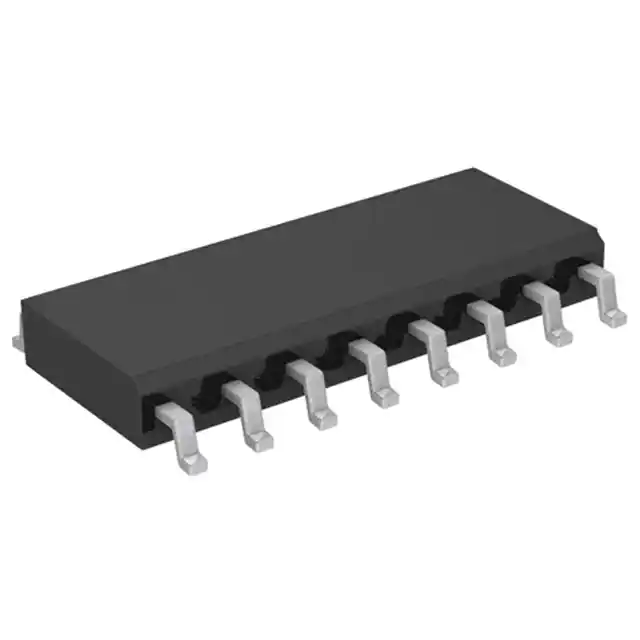
- Part No.:
- U2270B-MFPG3Y
- Manufacturer:
- Microchip Technology
- Category:
- RFID, RF Access, Monitoring ICs
- Package:
- 16-SOIC (0.154", 3.90mm Width)
- Datasheet:
-
 U2270B-MFPG3Y.pdf
- Description:
- IC RFID READER 100-150KHZ 16SO
- Quantity:
- Payment:

- Shipping:

Inventory:1,004
Please send an inquiry. Send us your inquiry, and we will respond immediately.
Product details
Overview
U2270B-MFPG3Y from Atmel is a 125 kHz RFID base station IC for contactless IDIC® read/write systems, integrating on-chip oscillator (100–150 kHz), coil driver, low-pass filter, Schmitt trigger, and microcontroller-compatible interface. It delivers up to 4.7 VPP driver output in battery-voltage mode, supports Manchester/bi-phase modulation at up to 5 Kbaud, and enables standby current as low as 30 µA - optimized for automotive immobilizer transceiver interfaces.
For engineers reviewing the U2270B-MFPG3Y datasheet, U2270B-MFPG3Y pinout, U2270B-MFPG3Y application, or U2270B-MFPG3Y equivalent, key selection criteria include its SO16 package, 125 kHz carrier tuning via RF pin resistor (110 kΩ), differential/common-mode coil drive capability, integrated 5V VS supply with standby control, and compatibility with 7–16 V battery input without external regulators.
Technical Context
The U2270B-MFPG3Y implements a fully integrated analog front-end for 125 kHz RFID base stations: its on-chip oscillator uses an external resistor (RF–VS) to set frequency with ±4 kHz tolerance at 125 kHz; the dual-coil driver supports both common-mode (high-current) and differential-mode (higher-voltage, improved sensitivity) configurations controlled by MS pin; and the 4th-order Butterworth low-pass filter has a cutoff at ~7 kHz when fOsc = 125 kHz.
Power architecture includes three distinct operation modes: one-rail (5 V only), two-rail (5 V + 7–8 V), and battery-voltage (7–16 V with internal regulation), where VEXT supplies external microcontrollers and DVS drives the coil via external NPN transistor. Standby mode disables VS while maintaining VEXT output, enabling ultra-low-power system wake-up.
Key Specifications
| Parameter | Value and Actual Design Meaning |
|---|---|
| Carrier Frequency | 100–150 kHz, factory-tuned to 125 kHz ±4 kHz using 110 kΩ RF–VS resistor |
| Data Rate Support | Up to 5 Kbaud with Manchester or bi-phase encoding; LPF cutoff at fOsc/18 enables reliable demodulation |
| Driver Output Swing | 4.3–4.7 VPP at ±100 mA in battery-voltage mode; supports 200 mA peak coil current |
| Supply Input Range | 7–16 V on VBatt; internal PS generates regulated VS (4.6–5.4 V) and VEXT (4.6–5.4 V) |
| Standby Current | 30–70 µA at 12 V; VS disabled while VEXT remains active to power MCU during sleep |
| Operating Temperature | –40°C to +105°C ambient; qualified for under-hood automotive environments |
| Package | SO16, Pb-free, tape-and-reel (MFPG3Y suffix); 9.9 mm × 3.8 mm body, 1.27 mm pitch |
Pinout & Package
U2270B-MFPG3Y is housed in a 16-pin SOIC (Small Outline Integrated Circuit) package with standard 1.27 mm pitch, 9.9 mm × 3.8 mm body, and exposed thermal pad not connected internally. Pin 1 is marked by a bevelled corner.
| Pin/Terminal | Circuit Role | Design Meaning |
|---|---|---|
| GND (Pin 1) | Ground reference | Analog/digital ground return; must be low-impedance connection to minimize noise coupling into LPF/AMP |
| OUTPUT (Pin 2) | Data output | Open-collector output; requires external pull-up; delivers demodulated data to MCU I/O pin |
| OE (Pin 3) | Output enable | Active-low control; OE = low enables OUTPUT; OE = high places output in high-Z state |
| INPUT (Pin 4) | Demodulated signal input | AC-coupled input (CIN); clamped ±2 V; feeds LPF and amplifier chain |
| MS (Pin 5) | Mode select | Configures COIL1/COIL2 as common-mode (low) or differential-mode (high) driver |
| CFE (Pin 6) | Carrier frequency enable | Controls RF field interruption for write operations to crypto/read-write transponders |
| DGND (Pin 7) | Driver ground | Separate ground for coil driver stage; improves EMI isolation from analog/digital sections |
| COIL2 (Pin 8) | Coil driver output 2 | Complements COIL1; used in differential mode for higher antenna voltage swing |
| COIL1 (Pin 9) | Coil driver output 1 | Primary coil driver output; tied to COIL2 in common-mode for higher current drive |
| VEXT (Pin 10) | External supply output | Regulated ~5 V output; powers external MCU even in STANDBY mode; max 10 mA load |
| DVS (Pin 11) | Driver supply voltage | Input for external NPN transistor base; sets coil driver rail voltage (up to 8 V) |
| VBatt (Pin 12) | Battery input | Main power input (7–16 V); overvoltage protected by internal Zener diodes |
| STANDBY (Pin 13) | Standby control | Active-low input; asserts STANDBY = low to disable VS and reduce quiescent current to µA range |
| VS (Pin 14) | Internal 5 V supply | Regulated output for core logic, oscillator, LPF, AMP; switched off in standby mode |
| RF (Pin 15) | Oscillator frequency adjust | Current-input pin; resistor to VS sets fOsc; enables fine-tuning near antenna resonance |
| HIPASS (Pin 16) | DC decoupling node | Connects external CHP capacitor; sets high-pass cutoff for amplifier input stage |
Key Features
| Feature | Design Value |
|---|---|
| Integrated 4th-order Butterworth LPF | Cuts carrier residue at fOsc/18 (~7 kHz @ 125 kHz); enables clean digital recovery without external filtering |
| Dual-mode coil driver (common/differential) | Differential mode increases effective antenna voltage swing and system sensitivity for >10 cm range |
| On-chip 5 V regulator with standby control | VS output shuts down in standby while VEXT remains live - enables zero-power MCU retention |
| Microcontroller-compatible interface | Open-collector OUTPUT with Schmitt trigger and 100 mV hysteresis ensures noise-immune TTL-level signaling |
| Battery-voltage operation (7–16 V) | Eliminates need for external 5 V regulator in automotive applications; includes load-dump protection support |
Applications
| Car Immobilizers | Animal Identification |
|---|---|
Use Scenario: Embedded in vehicle ignition control unit to energize and communicate with passive transponder key fob within 5–10 cm range. IC Role / Device Role / Timing Role: Base station controller generating 125 kHz magnetic field, demodulating backscatter response, and delivering decoded data to MCU via open-collector OUTPUT. Use Value: Enables secure challenge-response authentication using crypto transponders; differential coil drive extends detection range despite metal shielding in steering column. | Use Scenario: Integrated into handheld animal tag reader used in livestock farms for rapid ear-tag scanning during herd management. IC Role / Device Role / Timing Role: Low-power RFID base station providing regulated coil drive and robust demodulation for ISO 11784/11785-compliant tags. Use Value: Battery-voltage operation allows direct use of 9 V alkaline pack; standby mode extends field-reader runtime beyond 24 hours per charge. |
| Access Control | Process Control |
Use Scenario: Mounted inside industrial door lock panel to authenticate employee proximity cards in dusty, vibration-prone environments. IC Role / Device Role / Timing Role: Contactless reader IC supplying stable 125 kHz field and rejecting EMI from nearby motors or PLCs via HIPASS/CHP tuning. Use Value: Differential coil mode compensates for variable antenna coupling due to card orientation; CFE pin enables write-to-tag configuration updates onsite. | Use Scenario: Installed in automated assembly line fixture to verify presence and identity of RFID-tagged components before welding or dispensing. IC Role / Device Role / Timing Role: High-reliability base station interfacing with PLC via OUTPUT/OE, operating continuously in two-rail mode for extended coil voltage swing. Use Value: Two-rail operation (5 V + 7.5 V) delivers 6 VPP driver output, ensuring consistent read performance across temperature swings from –20°C to +70°C. |
Equivalent & Alternatives
The following parts are listed as comparable options for similar RFID base station applications.
| Alternative Part | Technical Difference | Application Difference | Selection Advice |
|---|---|---|---|
| SLI1300B | Single-coil driver; no differential mode; fixed 125 kHz oscillator; no VEXT output | Lacks VEXT-powered MCU support and standby mode; limited to simple read-only systems | Choose SLI1300B only if cost is critical and system requires no standby or external MCU supply |
| TDA8022 | Higher integration: includes EEPROM, watchdog, and enhanced security features; 5 V only supply | Requires external 5 V regulator; no battery-voltage operation; larger footprint (TSSOP20) | Select TDA8022 when cryptographic key storage and tamper detection are required, and board space permits TSSOP20 |
Compared with SLI1300B and TDA8022, U2270B-MFPG3Y uniquely balances automotive-grade battery operation, differential coil drive for sensitivity, and integrated VEXT supply - making it optimal for cost-sensitive, low-power immobilizer and access control designs requiring <10 cm range and MCU co-location.
Availability
U2270B-MFPG3Y is available at Aetrix Electronics and suitable for automotive immobilizer systems, industrial access control panels, livestock identification readers, and process automation fixtures requiring stable component supply across extended temperature ranges and long production lifecycles.
Supply support for U2270B-MFPG3Y includes scheduled delivery planning, volume procurement assistance, BOM continuity management, traceable sourcing, and lifecycle availability coordination for OEM customers, industrial embedded developers, connected-device designers, and electronics production programs.
Manufacturer
Atmel Corporation (now part of Microchip Technology) is a semiconductor manufacturer specializing in microcontrollers, touch technology, and secure RFID solutions for automotive, industrial, and consumer markets.
The U2270B-MFPG3Y belongs to Atmel's IDIC® RFID base station IC product line, designed specifically for 125 kHz contactless identification systems requiring low-power, high-sensitivity, and battery-voltage operation in harsh environments.
FAQ
What is the recommended resistor value between RF and VS pins for 125 kHz operation of the U2270B-MFPG3Y?
The U2270B-MFPG3Y requires a 110 kΩ resistor between RF (Pin 15) and VS (Pin 14) to achieve a nominal carrier frequency of 125 kHz. This value is specified in the datasheet's "Oscillator" section and accounts for internal compensation circuitry. Deviations beyond ±3% may shift fOsc outside the 121–129 kHz typical range, affecting transponder compatibility and read reliability. Always verify final frequency with a spectrum analyzer or RFID test transponder.
Can the U2270B-MFPG3Y operate directly from a 12 V car battery without external regulators?
Yes, the U2270B-MFPG3Y supports battery-voltage operation from 7–16 V on VBatt (Pin 12), with internal regulation generating VS (4.6–5.4 V) and VEXT (~5 V). In this mode, STANDBY (Pin 13) can disable VS while keeping VEXT active to power an external microcontroller. An external NPN transistor is required for DVS to drive the coil, and optional load-dump protection (resistor + capacitor) is recommended for automotive environments.
How does the MS pin affect coil driver behavior in the U2270B-MFPG3Y?
The MS (Mode Select) pin on the U2270B-MFPG3Y configures the COIL1 and COIL2 outputs: MS = low selects common-mode operation (outputs in phase, higher current capability), while MS = high selects differential-mode operation (outputs 180° out-of-phase, higher effective voltage across the antenna coil). Differential mode improves magnetic field strength and system sensitivity - especially beneficial for longer-range or metal-shielded applications like car immobilizers.
What is the maximum data rate supported by the U2270B-MFPG3Y, and which modulation schemes are compatible?
The U2270B-MFPG3Y supports a maximum data rate of 5 Kbaud at 125 kHz carrier frequency, confirmed in the "Features" section and validated by LPF cutoff at ~7 kHz (fOsc/18). It is explicitly designed for Manchester and bi-phase modulation, both of which are self-clocking and robust against amplitude variations. The Schmitt trigger output stage ensures clean TTL-level waveform reconstruction regardless of modulation type.
Does the U2270B-MFPG3Y provide any built-in protection against electrical overstress or thermal failure?
Yes, the U2270B-MFPG3Y includes multiple protections: internal Zener diodes on VBatt and VEXT pins limit overvoltage to safe levels; absolute maximum ratings specify 16 V on VBatt and 8 V on VS/VEXT/DVS/COIL pins; junction temperature is limited to 150°C; and thermal resistance RthJA is 120 K/W in SO16 package. These features ensure robustness in automotive environments, though external TVS diodes and proper PCB copper pour are still recommended for sustained load-dump events.
U2270B-MFPG3Y Specifications
- Product attributes
- Attribute value
- Manufacturer:
- Microchip Technology
- Series:
- U2270B
- Package/Case:
- 16-SOIC (0.154", 3.90mm Width)
- Packaging:
- Tape & Reel (TR)
- Product Status:
- Obsolete
- Type:
- RFID Reader
- Frequency:
- 100kHz ~ 150kHz
- Standards:
- -
- Interface:
- -
- Voltage - Supply:
- 8V ~ 16V
- Operating Temperature:
- -40°C ~ 105°C
- Grade:
- -
- Qualification:
- -
- Mounting Type:
- Surface Mount
- Supplier Device Package:
- 16-SO
U2270B-MFPG3Y FAQ
1.How can I place an order for U2270B-MFPG3Y through Aetrix?
Please submit a Request for Quotation (RFQ) for U2270B-MFPG3Y on Aetrix. Our sales agent will provide a competitive quotation and guide you through the order confirmation once you accept the terms.
2.Are the price and stock information for U2270B-MFPG3Y reliable?
The price and inventory of U2270B-MFPG3Y are updated periodically and may fluctuate due to market conditions. Stock and pricing data are typically refreshed every 24 hours. Quotation validity for U2270B-MFPG3Y is usually 5 days.
3.What payment methods are accepted for U2270B-MFPG3Y?
We accept Wire Transfer, PayPal, Credit Card, Western Union, MoneyGram, and Escrow for U2270B-MFPG3Y transactions.
Note: Certain payment methods may incur a processing fee.
4.How is shipping managed for U2270B-MFPG3Y?
U2270B-MFPG3Y orders can be shipped via leading logistics carriers, including DHL, UPS, FedEx, TNT, or Registered Mail.
Once your U2270B-MFPG3Y order is processed, you will receive an email with the shipment details and tracking number.
Note: Tracking information may take up to 24 hours to appear. Express delivery typically takes 3–5 business days.
5.How can I obtain technical support or documentation for U2270B-MFPG3Y?
For technical support, including U2270B-MFPG3Y datasheets, pinout diagrams, or application guidance, please contact our engineering support team. They can provide detailed documentation and assistance for your U2270B-MFPG3Y requirements.
6.How does Aetrix verify that U2270B-MFPG3Y is sourced from the original manufacturer or authorized distributors?
All U2270B-MFPG3Y products on Aetrix are procured from qualified distributors and authorized channels. Our dedicated quality assurance team conducts strict verification, including traceability checks and, if necessary, third-party testing. This ensures that U2270B-MFPG3Y meets industry standards.
7.What is the process for return or replacement of U2270B-MFPG3Y?
All U2270B-MFPG3Y units undergo pre-shipment inspection (PSI). If there is an issue with U2270B-MFPG3Y, returns or replacements are accepted under the following conditions:
1.Quantity discrepancies, incorrect items, or visible external defects (such as breakage or corrosion), acknowledged by Aetrix.
2.The issue is reported within 90 days of delivery.
3.The U2270B-MFPG3Y part is unused and in its original packaging.
Return procedure for U2270B-MFPG3Y:
1.Submit a request within 90 days.
2.Obtain a Return Material Authorization (RMA) from Aetrix.
U2270B-MFPG3Y Tags

-
SL2S2602FTBX
NXP Semiconductors

-
ST25DV04K-IER6S3
STMicroelectronics

-
ST25DV04K-IER6C3
STMicroelectronics
-
LXMSJZNCMD-217
Murata Electronics

-
NT3H2111W0FTTJ
NXP Semiconductors

-
NT3H2111W0FHKH
NXP Semiconductors

-
M24LR04E-RMC6T/2
STMicroelectronics
-
ST25DV04KC-JF6D3
STMicroelectronics

-
ST25DV64KC-IE6S3
STMicroelectronics

-
ST25DV64K-IER6T3
STMicroelectronics
-
NT3H2211W0FTTJ
NXP Semiconductors
-
NT3H2211W0FHKH
NXP Semiconductors
Tech Hub

TTL and CMOS logic families differ in thresholds, loading, output drive, power and timing. This engineering guide compares 74HC and 74HCT, calculates noise margins and checks 3.3 V/5 V compatibility.

A practical engineering guide to 3.3V and 5V logic compatibility, input thresholds, resistor dividers, translator ICs, MOSFET level shifting, I2C pull-ups, timing limits and power-sequencing risks.

The 74HC595 uses push-pull logic outputs, while the TPIC6B595 uses 50 V open-drain DMOS sinks for higher-power loads. This guide compares timing, current limits, 3.3 V interfacing, load wiring, thermal…

The 74HC595 converts serial data into eight stable parallel outputs. This guide covers pin functions, shift and storage timing, OE and MR behavior, drive-current limits, cascading, voltage compatibilit…

A technical comparison of level-sensitive latches and edge-triggered flip-flops, covering timing windows, setup and hold limits, master–slave operation, time borrowing, race-through, HDL inference and…

A D latch stores one bit while Enable controls when data can pass. This reference covers gate-level operation, truth tables, transparency, setup and hold timing, LE versus OE, common ICs and practical …

An SR latch stores one bit through cross-coupled feedback. This engineering reference covers NOR and NAND implementations, truth tables, forbidden-state recovery, gated operation, switch debouncing, fa…

Latch circuits retain one bit through feedback. This technical reference covers SR and D latches, truth tables, transparency, timing limits, latch-versus-flip-flop behavior, applications and common log…

An engineering guide to LED driver operation, constant-current and constant-voltage outputs, linear and switching topologies, dimming, IC selection, calculations, replacement compatibility, and fault c…

Operational amplifier guide covering op amp basics, feedback, ideal vs real op amps, common configurations, buffer circuits, offset, bias current, gain-bandwidth, slew rate, rail-to-rail limits and sel…


