
 My Inquiry
 My Account


onsemi UESD3.3DT5G
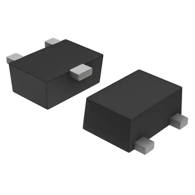
- Part No.:
- UESD3.3DT5G
- Manufacturer:
- onsemi
- Category:
- TVS Diodes
- Package:
- SOT-723
- Datasheet:
-
 UESD3.3DT5G.pdf
- Description:
- TVS DIODE 3.3VWM SOT723
- Quantity:
- Payment:

- Shipping:

Inventory:40,033
Please send an inquiry. Send us your inquiry, and we will respond immediately.
Product details
Overview
UESD3.3DT5G from onsemi is a unidirectional ESD protection diode in SOT-723 package, designed for I/O line protection in space-constrained portable electronics. It features 3.3 V working peak reverse voltage (VRWM), 5.0 V minimum breakdown voltage (VBR) at 1 mA, 47 pF typical capacitance at 0 V, <1 ns response time, and IEC61000-4-2 Level 4 (±30 kV air/±30 kV contact) ESD rating.
For engineers reviewing the UESD3.3DT5G datasheet, pinout, applications, or equivalent options, key selection criteria include clamping voltage under 16 A IPP, low leakage (<1.0 µA at VRWM), ultra-small footprint (1.20 mm × 0.80 mm), AEC-Q101 qualification, and compatibility with high-speed interfaces requiring sub-50 pF capacitance.
Technical Context
This device operates as a single-channel, cathode-common dual-cathode unidirectional TVS diode - pins 1 and 2 are both cathodes tied internally, pin 3 is the anode. Its clamping action begins at ~5.0 V (VBR), limiting transient voltages to ≤12.5 V at 16 A peak pulse current (IPP), enabling robust protection of 3.3 V logic rails without compromising signal integrity.
Designed for board-level ESD suppression per IEC61000-4-2 and IEC61000-4-4 standards, it delivers Class 3 HBM ESD immunity (>16 kV), supports reflow up to 260 °C, meets MSL 1, and uses 100% matte tin lead finish on a void-free thermoset epoxy case rated UL 94 V-0.
Key Specifications
| Parameter | Value and Actual Design Meaning |
|---|---|
| VRWM | 3.3 V - Maximum continuous reverse operating voltage before leakage exceeds 1.0 µA; matches 3.3 V I/O rail systems. |
| VBR (min) | 5.0 V @ 1 mA - Ensures reliable turn-on above normal operating voltage but below IC damage thresholds. |
| VC @ IPP=16 A | ≤12.5 V - Clamped voltage during 8/20 µs surge; keeps protected IC inputs within safe SOA. |
| C (typ) | 47 pF @ 0 V, 1 MHz - Low enough for USB 2.0, SDIO, and I²C signal lines without distortion. |
| Response Time | <1 ns - Fast enough to suppress ESD transients before they reach downstream circuitry. |
| ESD Rating | IEC61000-4-2 Level 4 (±30 kV air/±30 kV contact) - Meets highest industrial/portable equipment immunity requirements. |
| AEC-Q101 | Qualified - Validated for automotive infotainment and body electronics applications requiring reliability under thermal cycling and humidity. |
Pinout & Package
SOT-723 (Case 631AA, Style 4) is a 3-pin ultra-miniature surface-mount package measuring 1.20 mm × 0.80 mm × 0.50 mm, with 0.40 mm pitch and matte tin leads. It is void-free, UL 94 V-0 compliant, and rated for MSL 1 handling.
| Pin/Terminal | Circuit Role | Design Meaning |
|---|---|---|
| 1 | Cathode | Internally connected to pin 2; forms common cathode node for bidirectional clamping path to ground when used with external series impedance. |
| 2 | Cathode | Redundant cathode terminal - improves current sharing and thermal distribution during ESD events. |
| 3 | Anode | Connected to protected I/O line; reverse-biased during normal operation, conducts only during ESD overvoltage. |
Key Features
| Feature | Design Value |
|---|---|
| Ultra-small footprint | 1.20 mm × 0.80 mm - Enables placement directly at connector or IC pad, minimizing trace inductance and improving protection efficacy. |
| Low clamping voltage | ≤12.5 V @ 16 A - Limits stress on 3.3 V interface ICs such as USB transceivers and SD card controllers. |
| Sub-50 pF capacitance | 47 pF typ. - Preserves signal rise/fall times in high-speed digital interfaces up to 480 Mbps. |
| AEC-Q101 qualified | Validated for automotive temperature cycling, humidity, and mechanical shock - suitable for telematics and ADAS sensor interfaces. |
| Pb-free & RoHS compliant | 100% matte Sn finish, UL 94 V-0 epoxy - meets global environmental compliance and solderability requirements. |
Applications
| Smartphone Front Camera Interface | USB 2.0 Data Line Protection |
|---|---|
Use Scenario: Protecting MIPI CSI-2 differential data lines between image sensor and application processor from user-handling ESD. IC Role / Device Role / Timing Role: Unidirectional clamping diode placed at sensor connector to shunt ESD transients to ground before reaching serializer IC. Use Value: 47 pF capacitance avoids skew between D+ and D− lines; 3.3 V VRWM aligns with sensor I/O supply; dual-cathode layout reduces parasitic inductance. | Use Scenario: Safeguarding USB 2.0 D+ and D− lines on host controller against contact discharge during cable insertion. IC Role / Device Role / Timing Role: Standalone ESD suppressor mounted adjacent to USB receptacle, providing low-capacitance, fast-response protection. Use Value: ≤12.5 V clamping ensures PHY receiver input stays within absolute maximum ratings; SOT-723 allows co-placement with micro-USB port. |
| Automotive Infotainment Touchscreen | SD Card Slot ESD Guard |
Use Scenario: Shielding I²C-based touchscreen controller I/Os from ESD events in vehicle cabin environments. IC Role / Device Role / Timing Role: Single-channel protector on each I²C line (SDA/SCL), leveraging AEC-Q101 qualification for under-dash deployment. Use Value: 1.0 µA max leakage preserves bus pull-up integrity; 3.3 V VRWM matches controller VDDIO; MSL 1 enables standard SMT assembly. | Use Scenario: Preventing ESD-induced corruption or latch-up in embedded SDIO interfaces of portable medical devices. IC Role / Device Role / Timing Role: Point-of-entry protection on CMD, CLK, and DAT[0:3] lines before SD host controller. Use Value: 47 pF capacitance maintains SDHC timing margins; dual-cathode configuration supports shared ground return for multi-line protection. |
Equivalent & Alternatives
The following parts are listed as comparable options for similar ESD protection applications.
| Alternative Part | Technical Difference | Application Difference | Selection Advice |
|---|---|---|---|
| ESD3.3B1T5G | Same SOT-723 package, identical VRWM (3.3 V), but lower capacitance (22 pF) and higher VBR (6.0 V min). | Better suited for >100 Mbps interfaces (e.g., HDMI DDC, PCIe sideband); less margin for low-voltage logic. | Select when lower capacitance is critical and system can tolerate higher turn-on voltage. |
| CM1213A-03SO | 3-pin SOT-23 package (larger: 2.9 mm × 1.3 mm), 3.3 V VRWM, 45 pF, AEC-Q101 qualified. | Compatible with legacy SMT lines using SOT-23 tooling; higher thermal mass supports higher average power dissipation. | Choose if board real estate allows larger footprint and existing pick-and-place supports SOT-23. |
Compared with ESD3.3B1T5G and CM1213A-03SO, UESD3.3DT5G offers optimal balance of ultra-small size, 47 pF capacitance, and 5.0 V VBR for mainstream 3.3 V I/O protection - making it preferred for next-gen compact consumer and automotive modules where board space and signal fidelity are jointly constrained.
Availability
UESD3.3DT5G is available at Aetrix Electronics and suitable for smartphone camera modules, USB 2.0 peripheral interfaces, and automotive infotainment touchscreens requiring stable component supply across high-volume production cycles.
Supply support for UESD3.3DT5G includes scheduled delivery planning, volume procurement assistance, BOM continuity management, traceable sourcing, and lifecycle availability coordination for OEM customers, industrial embedded developers, connected-device designers, and electronics production programs.
Manufacturer
onsemi (formerly ON Semiconductor) is a global semiconductor supplier delivering energy-efficient, intelligent power and sensing solutions for automotive, industrial, cloud, medical, and IoT applications.
The ESD3.3DT5G belongs to onsemi's ESD3.3DT5G Series of ultra-small unidirectional TVS diodes, engineered specifically for high-density portable electronics where minimal PCB area and low signal distortion are mandatory.
FAQ
What is the maximum clamping voltage of UESD3.3DT5G under IEC61000-4-2 surge conditions?
The UESD3.3DT5G clamps to ≤12.5 V at 16 A peak pulse current (8/20 µs waveform), as specified in its electrical characteristics table. This value ensures protected 3.3 V logic circuits remain within safe operating limits during ESD events. The clamping performance is validated per IEC61000-4-2 Level 4 testing, and the UESD3.3DT5G datasheet confirms this parameter applies across the full operating temperature range.
Does UESD3.3DT5G support bidirectional ESD protection?
No, UESD3.3DT5G is a unidirectional ESD protection diode. Its pinout (pins 1 and 2 = cathode, pin 3 = anode) and electrical specs - including 3.3 V VRWM and 5.0 V VBR - confirm it is designed for reverse-biased operation on positive-rail I/O lines. For bidirectional protection, a separate device such as ESD7L5.0DT5G would be required.
Is UESD3.3DT5G compatible with lead-free reflow soldering processes?
Yes, UESD3.3DT5G is fully compatible with lead-free reflow. It features 100% matte tin lead finish and is qualified for peak reflow temperatures up to 260 °C (10-second duration), meeting JEDEC J-STD-020 MSL 1 requirements. The device's thermoset epoxy case is UL 94 V-0 rated and void-free, ensuring reliability under standard Pb-free thermal profiles.
What is the leakage current specification for UESD3.3DT5G at its rated working voltage?
The UESD3.3DT5G exhibits a maximum reverse leakage current of 1.0 µA at its working peak reverse voltage (VRWM) of 3.3 V and TA = 25 °C. This low leakage preserves signal integrity on high-impedance I²C, GPIO, and other sensitive interfaces, and remains stable across the full −55 °C to +150 °C junction temperature range per the datasheet's typical leakage vs. temperature curve.
Can UESD3.3DT5G be used in automotive applications?
Yes, UESD3.3DT5G is AEC-Q101 qualified and PPAP capable, making it suitable for automotive applications including infotainment displays, ADAS sensor interfaces, and body control modules. Its qualification covers temperature cycling, humidity resistance, and mechanical shock - and its 3.3 V VRWM and 47 pF capacitance align with common automotive MCU and sensor I/O requirements.
UESD3.3DT5G Specifications
- Product attributes
- Attribute value
- Manufacturer:
- onsemi
- Package/Case:
- SOT-723
- Series:
- uESD
- Packaging:
- Tape & Reel (TR)
- Product Status:
- Active
- Type:
- Zener
- Unidirectional Channels:
- 2
- Bidirectional Channels:
- -
- Voltage - Reverse Standoff (Typ):
- 3.3V (Max)
- Voltage - Breakdown (Min):
- 5V
- Voltage - Clamping (Max) @ Ipp:
- -
- Current - Peak Pulse (10/1000µs):
- -
- Power - Peak Pulse:
- -
- Power Line Protection:
- No
- Applications:
- General Purpose
- Capacitance @ Frequency:
- 80pF @ 1MHz
- Operating Temperature:
- -55°C ~ 150°C (TJ)
- Grade:
- -
- Qualification:
- -
- Mounting Type:
- Surface Mount
- Supplier Device Package:
- SOT-723
UESD3.3DT5G FAQ
1.How can I place an order for UESD3.3DT5G through Aetrix?
Please submit a Request for Quotation (RFQ) for UESD3.3DT5G on Aetrix. Our sales agent will provide a competitive quotation and guide you through the order confirmation once you accept the terms.
2.Are the price and stock information for UESD3.3DT5G reliable?
The price and inventory of UESD3.3DT5G are updated periodically and may fluctuate due to market conditions. Stock and pricing data are typically refreshed every 24 hours. Quotation validity for UESD3.3DT5G is usually 5 days.
3.What payment methods are accepted for UESD3.3DT5G?
We accept Wire Transfer, PayPal, Credit Card, Western Union, MoneyGram, and Escrow for UESD3.3DT5G transactions.
Note: Certain payment methods may incur a processing fee.
4.How is shipping managed for UESD3.3DT5G?
UESD3.3DT5G orders can be shipped via leading logistics carriers, including DHL, UPS, FedEx, TNT, or Registered Mail.
Once your UESD3.3DT5G order is processed, you will receive an email with the shipment details and tracking number.
Note: Tracking information may take up to 24 hours to appear. Express delivery typically takes 3–5 business days.
5.How can I obtain technical support or documentation for UESD3.3DT5G?
For technical support, including UESD3.3DT5G datasheets, pinout diagrams, or application guidance, please contact our engineering support team. They can provide detailed documentation and assistance for your UESD3.3DT5G requirements.
6.How does Aetrix verify that UESD3.3DT5G is sourced from the original manufacturer or authorized distributors?
All UESD3.3DT5G products on Aetrix are procured from qualified distributors and authorized channels. Our dedicated quality assurance team conducts strict verification, including traceability checks and, if necessary, third-party testing. This ensures that UESD3.3DT5G meets industry standards.
7.What is the process for return or replacement of UESD3.3DT5G?
All UESD3.3DT5G units undergo pre-shipment inspection (PSI). If there is an issue with UESD3.3DT5G, returns or replacements are accepted under the following conditions:
1.Quantity discrepancies, incorrect items, or visible external defects (such as breakage or corrosion), acknowledged by Aetrix.
2.The issue is reported within 90 days of delivery.
3.The UESD3.3DT5G part is unused and in its original packaging.
Return procedure for UESD3.3DT5G:
1.Submit a request within 90 days.
2.Obtain a Return Material Authorization (RMA) from Aetrix.
UESD3.3DT5G Tags

-
ESD9B5.0ST5G
onsemi

-
DESD3V3E1BL-7B
Diodes Incorporated

-
ESD5Z3.3T1G
onsemi
-
D5V0H1B2LP-7B
Diodes Incorporated
-
D5V0P1B2LP-7B
Diodes Incorporated

-
DESD5V0U1BA-7
Diodes Incorporated
-
ESD5Z5.0T1G
onsemi

-
DESD5V0U1BB-7
Diodes Incorporated
-
D12V0L1B2LP-7B
Diodes Incorporated

-
PESD2V0Y1BSFYL
Nexperia USA Inc.

-
DF2S5M4CT,L3F
Toshiba Semiconductor and Storage
-
D5V0L1B2WS-7
Diodes Incorporated
Tech Hub

Counterfeit components can hide behind convincing markings and passing basic function tests. This engineering reference covers source traceability, external inspection, X-ray, XRF, electrical testing, …

A practical engineering and sourcing framework covering lifecycle verification, lifetime-buy calculations, replacement qualification, supplier checks and counterfeit-risk controls.

TTL and CMOS logic families differ in thresholds, loading, output drive, power and timing. This engineering guide compares 74HC and 74HCT, calculates noise margins and checks 3.3 V/5 V compatibility.

A practical engineering guide to 3.3V and 5V logic compatibility, input thresholds, resistor dividers, translator ICs, MOSFET level shifting, I2C pull-ups, timing limits and power-sequencing risks.

The 74HC595 uses push-pull logic outputs, while the TPIC6B595 uses 50 V open-drain DMOS sinks for higher-power loads. This guide compares timing, current limits, 3.3 V interfacing, load wiring, thermal…

The 74HC595 converts serial data into eight stable parallel outputs. This guide covers pin functions, shift and storage timing, OE and MR behavior, drive-current limits, cascading, voltage compatibilit…

A technical comparison of level-sensitive latches and edge-triggered flip-flops, covering timing windows, setup and hold limits, master–slave operation, time borrowing, race-through, HDL inference and…

A D latch stores one bit while Enable controls when data can pass. This reference covers gate-level operation, truth tables, transparency, setup and hold timing, LE versus OE, common ICs and practical …

An SR latch stores one bit through cross-coupled feedback. This engineering reference covers NOR and NAND implementations, truth tables, forbidden-state recovery, gated operation, switch debouncing, fa…

Latch circuits retain one bit through feedback. This technical reference covers SR and D latches, truth tables, transparency, timing limits, latch-versus-flip-flop behavior, applications and common log…


