
 My Inquiry
 My Account


Renesas 2SK2084L-E
- Part No.:
- 2SK2084L-E
- Manufacturer:
- Renesas
- Category:
- FETs, MOSFETs
- Package:
- -
- Datasheet:
-
 2SK2084L-E.pdf
- Description:
- N-CHANNEL POWER MOSFET
- Quantity:
- Payment:

- Shipping:

Inventory:795
Please send an inquiry. Send us your inquiry, and we will respond immediately.
Product details
Overview
2SK2084L-E from Renesas Electronics is a silicon N-channel MOSFET designed for high-speed power switching in DC–DC converters and switching regulators. It features 20 V drain-to-source voltage rating, 7 A continuous drain current, 0.058 Ω RDS(on) at VGS = 4 V, 15 ns turn-on delay, and DPAK(L)-(2) surface-mount package with four-terminal drain configuration.
For engineers reviewing the 2SK2084L-E datasheet, 2SK2084L-E pinout, 2SK2084L-E application, or 2SK2084L-E equivalent, key selection criteria include low gate drive requirement (4 V compatible), fast switching performance (tr = 60 ns, tf = 80 ns), integrated body diode with 80 ns reverse recovery time, and thermal design support via 6.25°C/W channel-to-case thermal resistance.
Technical Context
This MOSFET operates as a single N-channel enhancement-mode switch optimized for synchronous rectification and primary-side switching in compact, high-efficiency power supplies. Its 0.04 Ω typical RDS(on) at VGS = 10 V and 4 A enables low conduction loss, while 800 pF input capacitance and 165 pF reverse transfer capacitance support stable gate driving at MHz-range frequencies.
The device integrates a body diode rated for 7 A reverse current and 0.9 V forward voltage at 7 A, enabling freewheeling operation without external diodes in buck or flyback topologies. Its 150°C maximum channel temperature and pulse-rated 28 A peak drain current accommodate transient load demands in regulated power stages.
Key Specifications
| Parameter | Value and Actual Design Meaning |
|---|---|
| VDSS | 20 V - Maximum blocking voltage before avalanche; sets upper limit for input voltage in 12 V–19 V DC-DC stages. |
| ID (continuous) | 7 A - Continuous current handling at Tc = 25°C; supports ≥35 W output in thermally managed designs. |
| RDS(on) @ 4 V | 0.058 Ω - On-resistance at logic-level gate drive; enables direct interface with 5 V microcontrollers or PWM ICs. |
| td(on)/tf | 15 ns / 80 ns - Fast turn-on and controlled fall time; reduces switching loss in 300 kHz–1 MHz converters. |
| Ciss | 800 pF - Input capacitance at VDS = 10 V; determines gate driver current demand and rise time in hard-switched circuits. |
| VGS(off) | 1.0–2.5 V - Gate threshold range; ensures reliable turn-off margin against noise in noisy power environments. |
| trr (body diode) | 80 ns - Reverse recovery time of integrated source-drain diode; critical for minimizing shoot-through risk in synchronous rectifiers. |
Pinout & Package
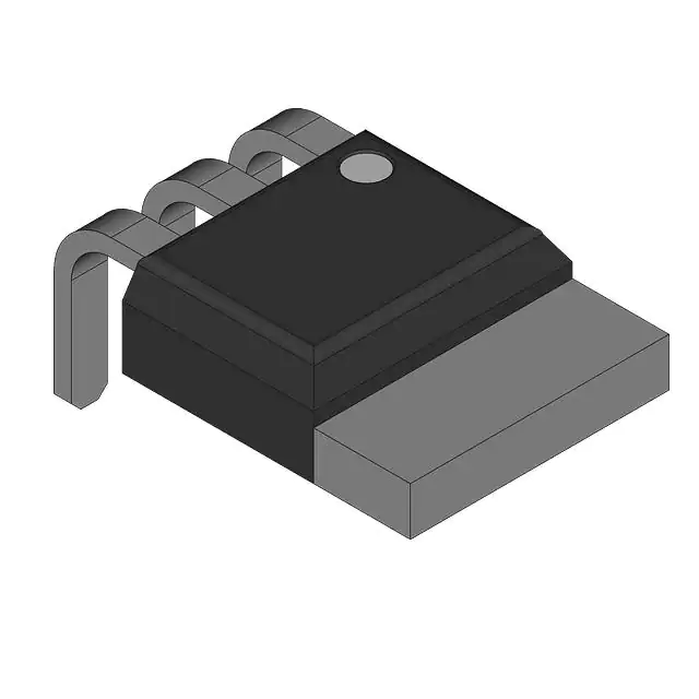
2SK2084L-E uses the DPAK(L)-(2) package (Renesas code PRSS0004ZD-B), a 4-pin surface-mount variant of the DPAK family with dual drain terminals for enhanced current handling and thermal spreading. The package measures 16.2 mm × 4.7 mm × 2.29 mm and weighs 0.42 g.
| Pin/Terminal | Circuit Role | Design Meaning |
|---|---|---|
| 1 | Gate | Control terminal; accepts 0–20 V gate drive; requires ≤10 µA leakage current at ±16 V bias. |
| 2 | Drain | Main high-side power terminal; electrically tied to pin 4; connects to input rail or transformer primary. |
| 3 | Source | Power return and reference node; ties to ground or low-side switch source; defines VGS reference. |
| 4 | Drain | Second drain terminal; paralleled internally with pin 2; improves current sharing and thermal path to PCB copper. |
Key Features
| Feature | Design Value |
|---|---|
| Low RDS(on) at 4 V drive | 0.058 Ω enables efficient operation with standard 5 V logic-level controllers without level-shifting circuitry. |
| High-speed switching | 15 ns td(on) and 80 ns tf reduce total switching loss in high-frequency DC–DC converters (>500 kHz). |
| Integrated body diode | 7 A rated, 0.9 V VDF, 80 ns trr supports synchronous rectification and freewheeling without external diode. |
| Dual-drain thermal design | Two drain pins (pins 2 & 4) lower thermal resistance and improve heat dissipation into PCB copper pour. |
| 4 V gate drive compatibility | Guaranteed turn-on with 4 V VGS; eliminates need for dedicated gate drivers in low-voltage control systems. |
Applications
| USB-C Power Delivery Adapter | Industrial 24 V DC–DC Converter |
|---|---|
Use Scenario: Step-down conversion from 20 V input to 5/9/15/20 V programmable output in compact USB-PD wall adapters. IC Role / Device Role / Timing Role: Primary-side synchronous rectifier switch in active-clamp or QR flyback topology. Use Value: Low 0.058 Ω RDS(on) at 4 V gate drive minimizes conduction loss under variable load, improving efficiency across 0–60 W range. | Use Scenario: Isolated 24 V input to 5 V/12 V dual-output supply for PLC I/O modules and sensor interfaces. IC Role / Device Role / Timing Role: Secondary-side synchronous rectifier in forward converter with center-tapped secondary winding. Use Value: Dual-drain layout and 6.25°C/W θch–c enable sustained 7 A operation on 2 oz copper without heatsink in industrial ambient (70°C). |
| Automotive Infotainment DC–DC Module | Point-of-Load Regulator for FPGA Core Supply |
Use Scenario: 12 V battery input to 3.3 V/1.2 V outputs powering display controllers and audio codecs in vehicle head units. IC Role / Device Role / Timing Role: High-side switch in buck regulator stage operating at 600 kHz switching frequency. Use Value: 800 pF Ciss and 15 ns td(on) allow clean, jitter-free switching with minimal gate drive power from automotive-grade PWM ICs. | Use Scenario: Tight-regulation 1.2 V core supply for Xilinx Artix-7 FPGA requiring <±1% tolerance and fast transient response. IC Role / Device Role / Timing Role: Low-side synchronous rectifier in multiphase buck converter with external controller. Use Value: 80 ns body diode trr prevents cross-conduction during dead-time, maintaining regulation stability under 10 A/µs load steps. |
Equivalent & Alternatives
The following parts are listed as comparable options for similar N-channel MOSFET applications.
| Alternative Part | Technical Difference | Application Difference | Selection Advice |
|---|---|---|---|
| ROHM RQ1C050BN | 20 V VDSS, 5 A ID, 0.045 Ω RDS(on) @ 4.5 V, TSMT6 package (smaller footprint, no dual drain) | Lower current rating and single-drain layout limit thermal headroom in >5 A continuous designs | Preferred for space-constrained consumer adapters where 5 A peak suffices and PCB area is premium. |
| ON Semiconductor NTMFS4C09NT1G | 30 V VDSS, 12.5 A ID, 0.0085 Ω RDS(on) @ 10 V, SO-8FL package | Higher voltage rating and lower on-resistance require 10 V gate drive; not logic-level compatible at 4 V | Suitable when system input may exceed 20 V or higher efficiency justifies added gate driver complexity. |
Compared with ROHM RQ1C050BN and ON Semiconductor NTMFS4C09NT1G, the 2SK2084L-E uniquely balances 4 V logic-level drive, dual-drain thermal robustness, and 7 A continuous rating-making it optimal for cost-sensitive, thermally constrained 20 V-class DC–DC converters where gate drive simplicity and reliability are prioritized over ultra-low RDS(on).
Availability
2SK2084L-E is available at Aetrix Electronics and suitable for USB-C power adapters, industrial 24 V DC–DC converters, and automotive infotainment power modules requiring stable component supply, long-term lifecycle support, and RoHS-compliant packaging.
Supply support for 2SK2084L-E includes scheduled delivery planning, volume procurement assistance, BOM continuity management, traceable sourcing, and lifecycle availability coordination for OEM customers, industrial embedded developers, connected-device designers, and electronics production programs.
Manufacturer
Renesas Electronics Corporation is a global semiconductor leader specializing in microcontrollers, analog, power, and SoC solutions for automotive, industrial, and infrastructure markets.
The 2SK2084L-E belongs to Renesas' legacy silicon MOSFET product line targeting high-efficiency, medium-power switching applications-designed specifically for cost-effective, thermally resilient DC–DC conversion in consumer and industrial power supplies.
FAQ
What is the maximum gate-to-source voltage rating for the 2SK2084L-E?
The 2SK2084L-E has a maximum gate-to-source voltage rating of ±20 V. This specification defines the absolute limit beyond which gate oxide integrity may be compromised. Operation within ±16 V is recommended for long-term reliability, as IGSS leakage remains ≤±10 µA at that bias. Exceeding ±20 V-even momentarily-risks irreversible gate damage. Always use clamping or zener protection in circuits with inductive gate traces or hot-swap conditions.
Does the 2SK2084L-E have an integrated body diode, and what are its key parameters?
Yes, the 2SK2084L-E includes an integrated body diode between source and drain. Its key parameters are 7 A reverse current rating (IDR), 0.9 V forward voltage at 7 A (VDF), and 80 ns reverse recovery time (trr) under IF = 7 A and diF/dt = 20 A/µs. These values are measured with VGS = 0 and confirm suitability for freewheeling and synchronous rectification in buck, flyback, and forward converters without external diode supplementation.
What is the thermal resistance from channel to case (θch–c) for the 2SK2084L-E?
The channel-to-case thermal resistance (θch–c) for the 2SK2084L-E is 6.25°C/W, specified at Tc = 25°C. This value is derived from the normalized transient thermal impedance curve and applies to steady-state conduction when the case is maintained at 25°C. For real-world PCB layouts, effective thermal resistance depends on copper area, thickness, and solder coverage-designers should verify junction temperature using θj–a or θj–c models with actual board construction.
Can the 2SK2084L-E be driven directly by a 3.3 V microcontroller GPIO pin?
No, the 2SK2084L-E cannot be reliably driven by a 3.3 V GPIO pin. Its gate threshold voltage (VGS(off)) ranges from 1.0 V to 2.5 V, but full enhancement requires ≥4 V to achieve the specified 0.058 Ω RDS(on). At 3.3 V, RDS(on) increases significantly-exceeding 0.1 Ω-and switching speed degrades. A gate driver or level shifter is required for robust operation with 3.3 V logic. The "4 V gate drive" feature refers to minimum functional drive-not 3.3 V compatibility.
What is the difference between the 2SK2084L-E and 2SK2084S variants?
The 2SK2084L-E uses the DPAK(L)-(2) package (Renesas code PRSS0004ZD-B) with 16.2 mm length and dual drain terminals, while the 2SK2084S uses the smaller DPAK(S) package (PRSS0004ZD-C) measuring 5.4 mm in length and featuring a single drain terminal. Both share identical electrical specifications-including VDSS, ID, RDS(on), and switching times-but differ in thermal performance and current-handling capability due to package geometry and terminal count. The L-E variant supports higher continuous current in thermally demanding applications.
2SK2084L-E Specifications
- Product attributes
- Attribute value
- Manufacturer:
- Renesas
- Series:
- *
- Package/Case:
- -
- Packaging:
- Bulk
- Product Status:
- Active
- FET Type:
- -
- Technology:
- -
- Drain to Source Voltage (Vdss):
- -
- Current - Continuous Drain (Id) @ 25°C:
- -
- Drive Voltage (Max Rds On, Min Rds On):
- -
- Rds On (Max) @ Id, Vgs:
- -
- Vgs(th) (Max) @ Id:
- -
- Gate Charge (Qg) (Max) @ Vgs:
- -
- Vgs (Max):
- -
- Input Capacitance (Ciss) (Max) @ Vds:
- -
- FET Feature:
- -
- Power Dissipation (Max):
- -
- Operating Temperature:
- -
- Grade:
- -
- Qualification:
- -
- Mounting Type:
- -
- Supplier Device Package:
- -
2SK2084L-E FAQ
1.How can I place an order for 2SK2084L-E through Aetrix?
Please submit a Request for Quotation (RFQ) for 2SK2084L-E on Aetrix. Our sales agent will provide a competitive quotation and guide you through the order confirmation once you accept the terms.
2.Are the price and stock information for 2SK2084L-E reliable?
The price and inventory of 2SK2084L-E are updated periodically and may fluctuate due to market conditions. Stock and pricing data are typically refreshed every 24 hours. Quotation validity for 2SK2084L-E is usually 5 days.
3.What payment methods are accepted for 2SK2084L-E?
We accept Wire Transfer, PayPal, Credit Card, Western Union, MoneyGram, and Escrow for 2SK2084L-E transactions.
Note: Certain payment methods may incur a processing fee.
4.How is shipping managed for 2SK2084L-E?
2SK2084L-E orders can be shipped via leading logistics carriers, including DHL, UPS, FedEx, TNT, or Registered Mail.
Once your 2SK2084L-E order is processed, you will receive an email with the shipment details and tracking number.
Note: Tracking information may take up to 24 hours to appear. Express delivery typically takes 3–5 business days.
5.How can I obtain technical support or documentation for 2SK2084L-E?
For technical support, including 2SK2084L-E datasheets, pinout diagrams, or application guidance, please contact our engineering support team. They can provide detailed documentation and assistance for your 2SK2084L-E requirements.
6.How does Aetrix verify that 2SK2084L-E is sourced from the original manufacturer or authorized distributors?
All 2SK2084L-E products on Aetrix are procured from qualified distributors and authorized channels. Our dedicated quality assurance team conducts strict verification, including traceability checks and, if necessary, third-party testing. This ensures that 2SK2084L-E meets industry standards.
7.What is the process for return or replacement of 2SK2084L-E?
All 2SK2084L-E units undergo pre-shipment inspection (PSI). If there is an issue with 2SK2084L-E, returns or replacements are accepted under the following conditions:
1.Quantity discrepancies, incorrect items, or visible external defects (such as breakage or corrosion), acknowledged by Aetrix.
2.The issue is reported within 90 days of delivery.
3.The 2SK2084L-E part is unused and in its original packaging.
Return procedure for 2SK2084L-E:
1.Submit a request within 90 days.
2.Obtain a Return Material Authorization (RMA) from Aetrix.
2SK2084L-E Tags
-
BSZ180P03NS3EGATMA1
Infineon Technologies
-
SIRA14DP-T1-GE3
Vishay Siliconix

-
AO4419
Alpha & Omega Semiconductor Inc.
-
SISA14BDN-T1-GE3
Vishay Siliconix
-
PSMN9R5-30YLC,115
Nexperia USA Inc.
-
BUK9Y21-40E,115
Nexperia USA Inc.
-
RTQ035N03HZGTR
Rohm Semiconductor
-
FDMS7680
onsemi
-
RQ3E180BNTB
Rohm Semiconductor
-
STL6N2VH5
STMicroelectronics
-
DMPH4029LFGQ-7
Diodes Incorporated
-
DMT6015LSS-13
Diodes Incorporated
Tech Hub

TTL and CMOS logic families differ in thresholds, loading, output drive, power and timing. This engineering guide compares 74HC and 74HCT, calculates noise margins and checks 3.3 V/5 V compatibility.

A practical engineering guide to 3.3V and 5V logic compatibility, input thresholds, resistor dividers, translator ICs, MOSFET level shifting, I2C pull-ups, timing limits and power-sequencing risks.

The 74HC595 uses push-pull logic outputs, while the TPIC6B595 uses 50 V open-drain DMOS sinks for higher-power loads. This guide compares timing, current limits, 3.3 V interfacing, load wiring, thermal…

The 74HC595 converts serial data into eight stable parallel outputs. This guide covers pin functions, shift and storage timing, OE and MR behavior, drive-current limits, cascading, voltage compatibilit…

A technical comparison of level-sensitive latches and edge-triggered flip-flops, covering timing windows, setup and hold limits, master–slave operation, time borrowing, race-through, HDL inference and…

A D latch stores one bit while Enable controls when data can pass. This reference covers gate-level operation, truth tables, transparency, setup and hold timing, LE versus OE, common ICs and practical …

An SR latch stores one bit through cross-coupled feedback. This engineering reference covers NOR and NAND implementations, truth tables, forbidden-state recovery, gated operation, switch debouncing, fa…

Latch circuits retain one bit through feedback. This technical reference covers SR and D latches, truth tables, transparency, timing limits, latch-versus-flip-flop behavior, applications and common log…

An engineering guide to LED driver operation, constant-current and constant-voltage outputs, linear and switching topologies, dimming, IC selection, calculations, replacement compatibility, and fault c…

Operational amplifier guide covering op amp basics, feedback, ideal vs real op amps, common configurations, buffer circuits, offset, bias current, gain-bandwidth, slew rate, rail-to-rail limits and sel…


